MMWAVEICBOOST+IWR6843ISK运行tm_visualizer.exe里面Test connection报错问题(困扰很久了)

Other Parts Discussed in Thread: MMWAVEICBOOST, IWR6843ISK, IWR6843, UNIFLASH

您好!

该问题一直未解决,尝试更换单板,更换电脑,卸载软件又重新安装,问题仍然存在。

附:

硬件环境:MMWAVEICBOOST+IWR6843ISK
1.MMWAVEICBOOST上已经设置001功能模式
2.PC上的串口xds110 class Application/User UART(COM5)
xds110 class Auxiliary Data Port(COM6)
软件环境:
1.安装Matlab runtime2019(a)
2.已经成功烧写long_range_people_det_68xx_demo.bin

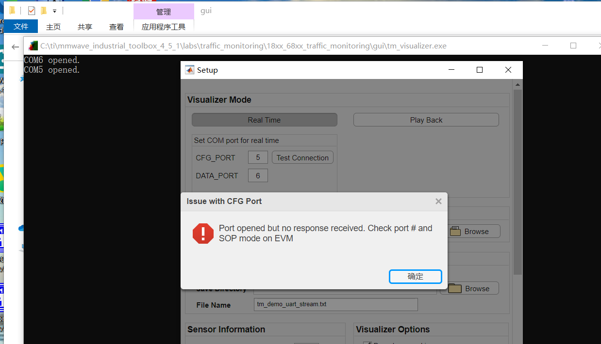
打开mmwave_industrial_toolbox_4_5_1\labs\traffic_monitoring\18xx_68xx_traffic_monitoring\gui里面的tm_visualizer.exe在
Test connection这一步报错,如下:

  • 你好,

    错误提示,应该是板子上的代码没有相应。

    请问你这个ISK板子上的IWR6843芯片是ES2.0的还是ES1.0的?注意这个版本toolbox的TM demo支持的是ES2.0的芯片。
  • 你好!是ES2.0的,曾经成功跑过E:\out_of_box_demo\68xx_mmwave_sdk_dsp里面的例程

  • 你好,

    你说更换过单板,请现在这块板子是否成功运行过out of box demo?
    上电后是否有尝试按一下MMWAVEicBOOST上的复位按钮,然后再尝试demo?
    请问MMWAVEicBOOST上的S1上的开关是否确认正确?
  • 该单板成功运行过out of demo.按过复位按钮,S1开关按照用户手册对应的
    hw_setup_antenna_module_and_carrier_for_functional.html里面的设置的
  • 你好,

    如果硬件/硬件设置都没有问题,建议你把IWR6843连上CCS,看看在PC GUI通过串口向IWR6843发送命令后,出现了什么错误导致没有正确相应。
  • 如果连接CCS,是不是要先烧写xwr68xx_ccsdebug.bin?关键是uniflash,也不太稳定,我是折腾了两天,才成功烧写进long_range_people_det_68xx_demo.bin文件。
  • 你好,

    你能否确认你使用的5V电源的电流足够?能否使用一个较大电流的5V电源,再尝试一下。烧写前可以线按一下复位按钮。
  • 另,请使用EVM自带的原装usb线。
  • 购买单板的时候,没有配套的线,如果购买原装usb线,麻烦问一下在哪里买?电源我使用的通过USB线连接到笔记本。以前一直是这样供电的,能跑out of demo的例程,现在又试了一下5V/2A,5V/4A的,暂时都还是一样的报错。手上暂时没有5V/3A的
  • 你好,

    MMWAVEICBOOST里面是有带usb线缆的。

    你之前说烧写也不稳定,有可能就是电源的问题。

    如果是IWR6843ISK revC或者更高版本,通过电脑usb供电是可以的。

    如果是IWR6843ISK+MMWAVEICBOOST,请使用电源适配器,如果你使用电源适配器不确认电流输出是否和标称一致,使用5V5A的比较保险。如果你那里有直流电源就更好了,电流应该不是问题,可以尝试确认一下是否是输入电压电流导致的问题。

  • 目前我更换了电源,烧写xwr68xx_ccsdebug.bin成功了,更换功能模式后,打开ccs,连接串口,报错如下:
    [Start: Texas Instruments XDS110 USB Debug Probe_0]

    Execute the command:

    %ccs_base%/common/uscif/dbgjtag -f %boarddatafile% -rv -o -S integrity

    [Result]


    -----[Print the board config pathname(s)]------------------------------------

    C:\Users\yutao\AppData\Local\TEXASI~1\CCS\
    ccs930\0\0\BrdDat\testBoard.dat

    -----[Print the reset-command software log-file]-----------------------------

    This utility has selected a 100- or 510-class product.
    This utility will load the adapter 'jioxds110.dll'.
    The library build date was 'Nov 25 2019'.
    The library build time was '16:55:29'.
    The library package version is '8.4.0.00006'.
    The library component version is '35.35.0.0'.
    The controller does not use a programmable FPGA.
    The controller has a version number of '5' (0x00000005).
    The controller has an insertion length of '0' (0x00000000).
    This utility will attempt to reset the controller.
    This utility has successfully reset the controller.

    -----[Print the reset-command hardware log-file]-----------------------------

    The scan-path will be reset by toggling the JTAG TRST signal.
    The controller is the XDS110 with USB interface.
    The link from controller to target is direct (without cable).
    The software is configured for XDS110 features.
    The controller cannot monitor the value on the EMU[0] pin.
    The controller cannot monitor the value on the EMU[1] pin.
    The controller cannot control the timing on output pins.
    The controller cannot control the timing on input pins.
    The scan-path link-delay has been set to exactly '0' (0x0000).

    -----[An error has occurred and this utility has aborted]--------------------

    This error is generated by TI's USCIF driver or utilities.

    The value is '-233' (0xffffff17).
    The title is 'SC_ERR_PATH_BROKEN'.

    The explanation is:
    The JTAG IR and DR scan-paths cannot circulate bits, they may be broken.
    An attempt to scan the JTAG scan-path has failed.
    The target's JTAG scan-path appears to be broken
    with a stuck-at-ones or stuck-at-zero fault.

    [End: Texas Instruments XDS110 USB Debug Probe_0]
  • 目前已经能连接上串口,通过CCS能成功下载程序了