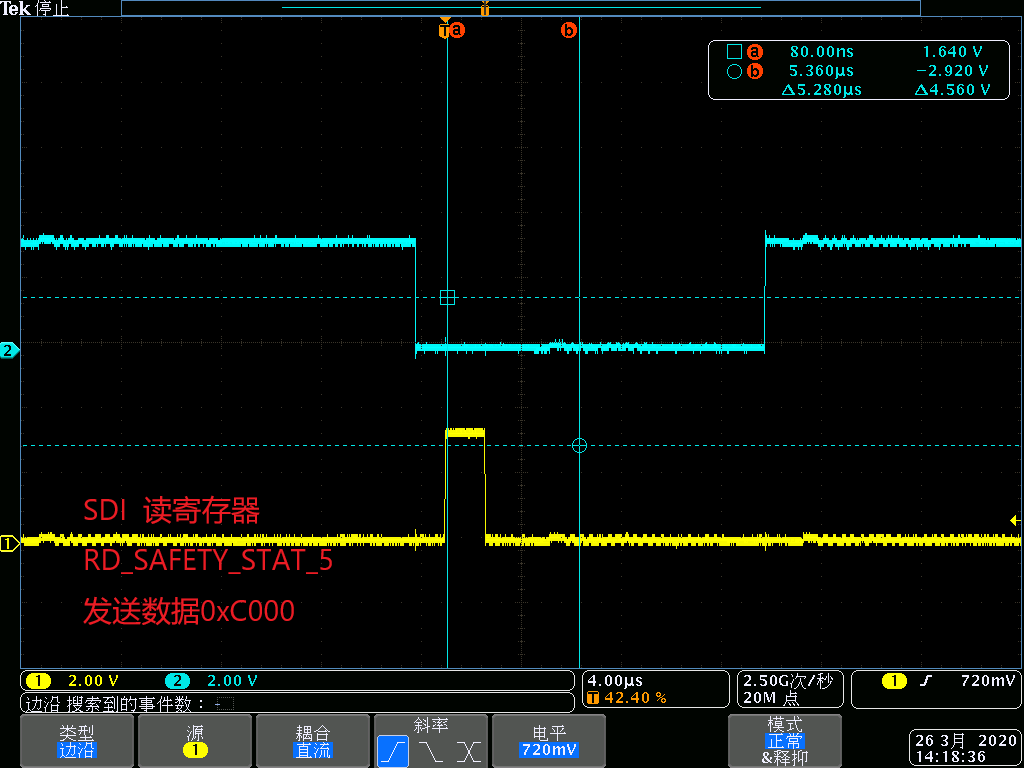
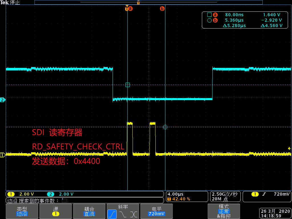
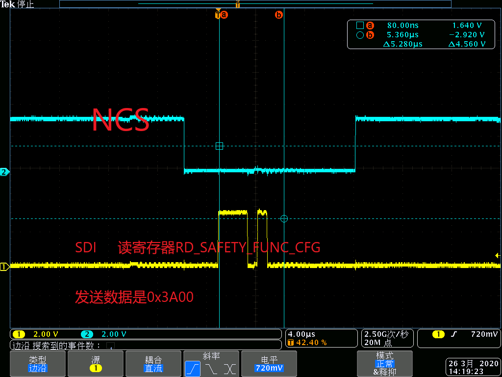
目前在研究28375 与电源管理芯片TPS65381 SPI通讯问题,一直无法读取TPS65381寄存器的数据;还请各位帮我看下代码是否有问题?
SPI配置:
void InitSpicGpio()
{

   EALLOW;

/* Enable internal pull-up for the selected pins */
// Pull-ups can be enabled or disabled by the user.
// This will enable the pullups for the specified pins.
// Comment out other unwanted lines.

    GpioCtrlRegs.GPCPUD.bit.GPIO69 = 0;   // Enable pull-up on GPIO69 (SPISIMOC)
//  GpioCtrlRegs.GPAPUD.bit.GPIO5 = 0;    // Enable pull-up on GPIO5 (SPISIMOA)
    GpioCtrlRegs.GPCPUD.bit.GPIO70 = 0;   // Enable pull-up on GPIO70 (SPISOMIC)
//  GpioCtrlRegs.GPAPUD.bit.GPIO3 = 0;    // Enable pull-up on GPIO3 (SPISOMIA)
    GpioCtrlRegs.GPCPUD.bit.GPIO71 = 0;   // Enable pull-up on GPIO71 (***)
    GpioCtrlRegs.GPCPUD.bit.GPIO72 = 0;   // Enable pull-up on GPIO72 (SPISTEC)

/* Set qualification for selected pins to asynch only */
// This will select asynch (no qualification) for the selected pins.
// Comment out other unwanted lines.

    GpioCtrlRegs.GPCQSEL1.bit.GPIO69 = 3; // Asynch input GPIO69 (SPISIMOC)
//  GpioCtrlRegs.GPAQSEL1.bit.GPIO5 = 3;  // Asynch input GPIO5 (SPISIMOA)
    GpioCtrlRegs.GPCQSEL1.bit.GPIO70 = 3; // Asynch input GPIO70 (SPISOMIC)
//  GpioCtrlRegs.GPAQSEL1.bit.GPIO3 = 3;  // Asynch input GPIO3 (SPISOMIA)
    GpioCtrlRegs.GPCQSEL1.bit.GPIO71 = 3; // Asynch input GPIO71 (***)
    GpioCtrlRegs.GPCQSEL1.bit.GPIO72 = 3; // Asynch input GPIO72 (SPISTEC)

/* Configure SPI-A pins using GPIO regs*/
// This specifies which of the possible GPIO pins will be SPI functional pins.
// Comment out other unwanted lines.

    GpioCtrlRegs.GPCMUX1.bit.GPIO69 = 1; // Configure GPIO69 as SPISIMOC
//  GpioCtrlRegs.GPAMUX1.bit.GPIO5 = 2;  // Configure GPIO5 as SPISIMOA
    GpioCtrlRegs.GPCMUX1.bit.GPIO70 = 1; // Configure GPIO70 as SPISOMIC
//  GpioCtrlRegs.GPAMUX1.bit.GPIO3 = 2;  // Configure GPIO3 as SPISOMIA
    GpioCtrlRegs.GPCMUX1.bit.GPIO71 = 1; // Configure GPIO71 as ***
    GpioCtrlRegs.GPCMUX1.bit.GPIO72 = 1; // Configure GPIO72 as SPISTEC

    EDIS;
}
void InitTPS65381ASpi(void)
{
	GPIO_SetupPinMux(68,0,0);			// RESET_POWER,数字电源看门狗及复位,DSP输出给TPS65381A,低电平有效
	GPIO_SetupPinOptions(68,1,0);
	GpioDataRegs.GPCCLEAR.bit.GPIO68 = 0;

	GPIO_SetupPinMux(69,0,6);			// SDI,SIMO
	GPIO_SetupPinOptions(69,1,GPIO_ASYNC | GPIO_PULLUP);
	//GpioDataRegs.GPCCLEAR.bit.GPIO70 = 1;

	GPIO_SetupPinMux(70,0,6);			// SDO,SOMI
	GPIO_SetupPinOptions(70,0,GPIO_ASYNC | GPIO_PULLUP);


	GPIO_SetupPinMux(71,0,6);			// SCLK,CLK
	GPIO_SetupPinOptions(71,1,GPIO_ASYNC | GPIO_PULLUP);

	GPIO_SetupPinMux(72,0,6);			// NCS,CS
	GPIO_SetupPinOptions(72,1,GPIO_ASYNC | GPIO_PULLUP);


	EALLOW;

	***.***.all =0x004F;	             // Reset on, rising edge, 16-bit char bits
	***.***.all =0x0006;    		     // Enable master mode, normal phase,
	***.SPIBRR.all =39;//24;//0x0009;        // *** = 200M / 4 / (7) = 7.14M,*** MAX is 8M
	***.SPISTS.all = 0x0000;                // reset all status information
	***.SPIPRI.all = 0x0010;                // Set so breakpoints don't disturb xmission
	//***.***.bit.SPILBK = 1;


	/* reset both fifos */
	***.SPIFFTX.bit.TXFIFO = 0;
	***.SPIFFRX.bit.RXFIFORESET = 0; /*and keep them in reset during configuration */
	/* configure fifos  */
	***.SPIFFTX.all = 0x4041; /* Enable FIFO's, do not use interrupts */
	***.SPIFFRX.all = 0x4041; /* Set RX FIFO, do not use interrupts  */
	***.SPIFFCT.all = 0x0000; /* no delay between FIFO and TXBUF */
	/* releasing fifos from reset */
	***.SPIFFTX.bit.TXFIFO = 1;    /* enable tx */
	***.SPIFFRX.bit.RXFIFORESET = 1; /* enable rx */

	***.***.bit.SPISWRESET = 1;
	EDIS;
}

读寄存器code
uint16 ReadRegsTPS65381(uint16 RegAddr)
{
	uint16 rx = 0x0;
#if 0
	EALLOW;
	GpioDataRegs.GPCDAT.bit.GPIO72 = 0;
	EDIS;
#endif
	rx |= ((RegAddr << 8) & 0xffff);
    ***.SPITXBUF = rx;
    /* wait until the transmission is finished */
    while (***.SPIFFRX.bit.RXFFST < 1)
    	{}
    //rx = ***.SPIRXBUF & 0xff;
	rx = ***.SPIRXBUF;
#if 0
	EALLOW;
	GpioDataRegs.GPCDAT.bit.GPIO72 = 1;
	EDIS;
#endif
	return (rx);
}