This thread has been locked.

If you have a related question, please click the "Ask a related question" button in the top right corner. The newly created question will be automatically linked to this question.

使用timmer的定时器无法进入第二次中断程序

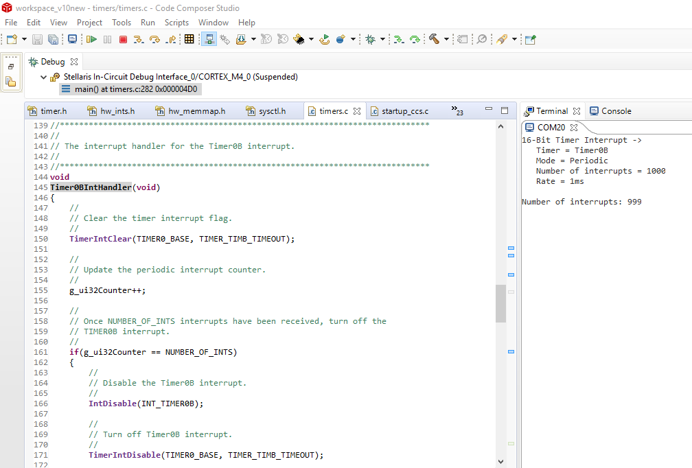
本人在编写用定时器控制单片机中断20次的实验中,发现无法进入第二次中断,进入第一次中断后就一直在while循环,也清除了标志位,麻烦大神帮看一下

5415.timers.c
//*****************************************************************************
//
// timers.c - Timers example.
//
// Copyright (c) 2013 Texas Instruments Incorporated.  All rights reserved.
// Software License Agreement
// 
// Texas Instruments (TI) is supplying this software for use solely and
// exclusively on TI's microcontroller products. The software is owned by
// TI and/or its suppliers, and is protected under applicable copyright
// laws. You may not combine this software with "viral" open-source
// software in order to form a larger program.
// 
// THIS SOFTWARE IS PROVIDED "AS IS" AND WITH ALL FAULTS.
// NO WARRANTIES, WHETHER EXPRESS, IMPLIED OR STATUTORY, INCLUDING, BUT
// NOT LIMITED TO, IMPLIED WARRANTIES OF MERCHANTABILITY AND FITNESS FOR
// A PARTICULAR PURPOSE APPLY TO THIS SOFTWARE. TI SHALL NOT, UNDER ANY
// CIRCUMSTANCES, BE LIABLE FOR SPECIAL, INCIDENTAL, OR CONSEQUENTIAL
// DAMAGES, FOR ANY REASON WHATSOEVER.
// 
// This is part of revision 2.0.1.11577 of the DK-TM4C129X Firmware Package.
//
//*****************************************************************************

#include <stdbool.h>
#include <stdint.h>
#include "inc/hw_ints.h"
#include "inc/hw_memmap.h"
#include "driverlib/rom_map.h"
#include "inc/hw_types.h"
#include "inc/hw_gpio.h"
#include "driverlib/pin_map.h"
#include "driverlib/interrupt.h"
#include "driverlib/rom.h"
#include "driverlib/sysctl.h"
#include "driverlib/timer.h"
#include "grlib/grlib.h"
#include "drivers/frame.h"
#include "drivers/kentec320x240x16_ssd2119.h"
#include "drivers/pinout.h"
#include "driverlib/debug.h"
#include "driverlib/gpio.h"
#include "driverlib/uart.h"
#include "inc/hw_uart.h"
#include "utils/uartstdio.h"
#include <stdarg.h>


//*****************************************************************************
//
//! \addtogroup example_list
//! <h1>Timer (timers)</h1>
//!
//! This example application demonstrates the use of the timers to generate
//! periodic interrupts.  One timer is set up to interrupt once per second and
//! the other to interrupt twice per second; each interrupt handler will toggle
//! its own indicator on the display.
//
//*****************************************************************************

//*****************************************************************************

//*****************************************************************************
//
// The error routine that is called if the driver library encounters an error.
//
//*****************************************************************************
#ifdef DEBUG
void
__error__(char *pcFilename, uint32_t ui32Line)
{
}
#endif

//*****************************************************************************
//
// The interrupt handler for the first timer interrupt.
//
//*****************************************************************************

#define NUMBER_OF_INTS 20

static volatile uint32_t g_ui32Counter = 0;


//*****************************************************************************
//
// This example application demonstrates the use of the timers to generate
// periodic interrupts.
//
//*****************************************************************************
void
InitConsole(void)
{
  SysCtlPeripheralEnable(SYSCTL_PERIPH_GPIOA);
  GPIOPinConfigure(GPIO_PA0_U0RX);
  GPIOPinConfigure(GPIO_PA1_U0TX);
  SysCtlPeripheralEnable(SYSCTL_PERIPH_UART0);
  UARTClockSourceSet(UART0_BASE, UART_CLOCK_PIOSC);
  GPIOPinTypeUART(GPIO_PORTA_BASE,GPIO_PIN_0|GPIO_PIN_1);
  UARTStdioConfig(0,115200,16000000);
}
int main(void)
{
        uint32_t ui32PrevCount = 0;

        SysCtlClockSet(SYSCTL_SYSDIV_1|SYSCTL_USE_OSC|SYSCTL_OSC_MAIN|SYSCTL_XTAL_16MHZ);
        InitConsole();
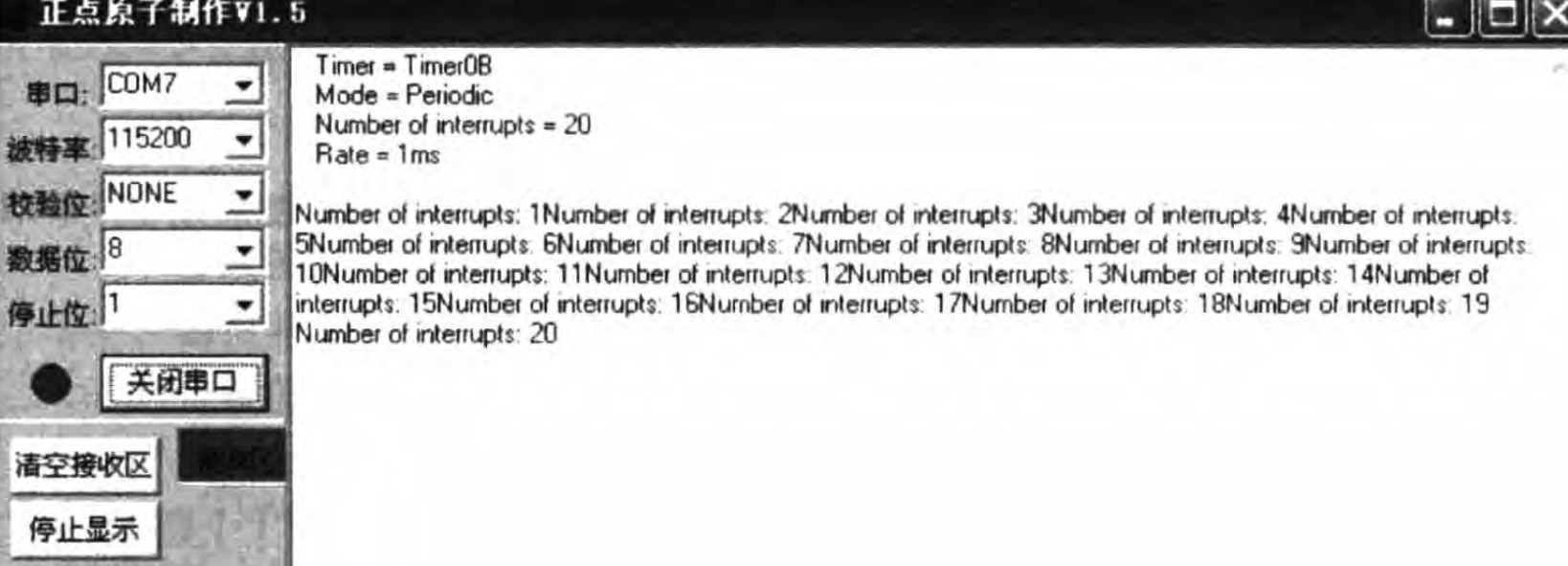
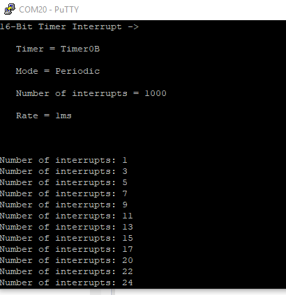
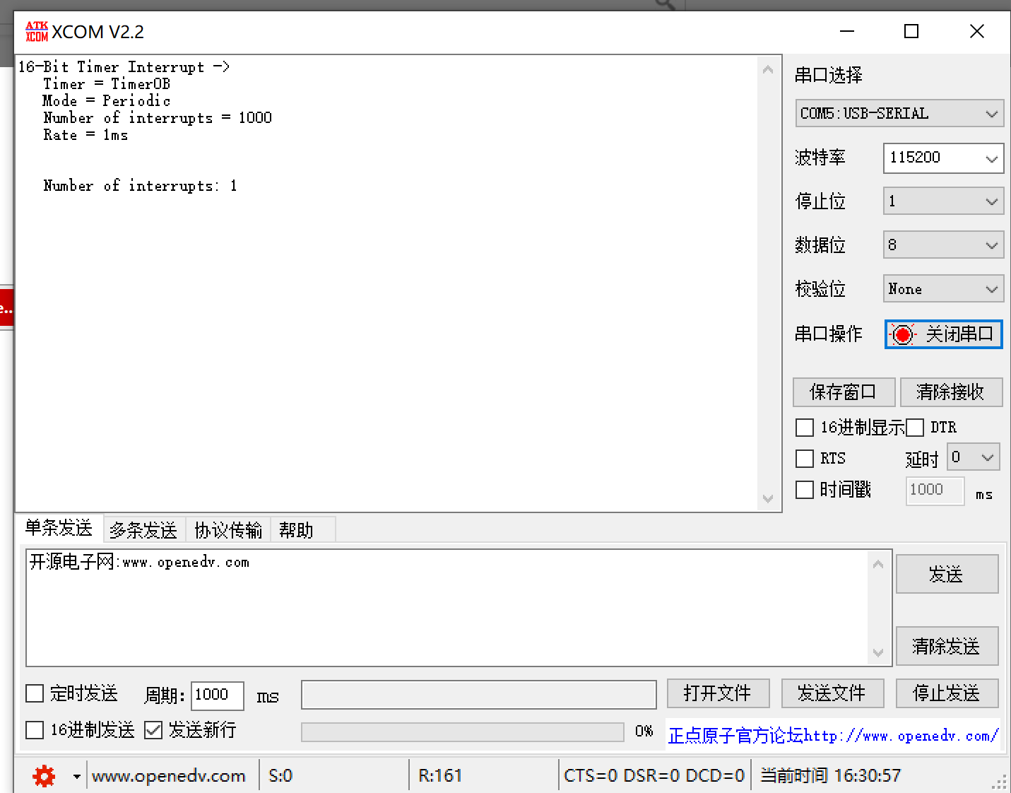
        UARTprintf("16 - Bit Timer Interrupt - >");
        UARTprintf("\n Timer = Timer0B");
        UARTprintf("\n Mode = Periodic");
        UARTprintf("\n Number of interrupts = %d",NUMBER_OF_INTS);
        UARTprintf("\n Rate = 1ms\n\n");
        ROM_SysCtlPeripheralEnable(SYSCTL_PERIPH_GPION);
        ROM_SysCtlDelay(1);
        ROM_GPIOPinTypeGPIOOutput(GPIO_PORTN_BASE, GPIO_PIN_0);
        SysCtlPeripheralEnable(SYSCTL_PERIPH_TIMER0);
        TimerConfigure(TIMER0_BASE, TIMER_CFG_SPLIT_PAIR | TIMER_CFG_PERIODIC);

        TimerLoadSet(TIMER0_BASE, TIMER_B, SysCtlClockGet()/50);

        IntEnable(INT_TIMER0B);
        TimerIntEnable(TIMER0_BASE, TIMER_TIMB_TIMEOUT);
        IntMasterEnable();
        TimerIntRegister(TIMER0_BASE, TIMER_B, Timer0IntHandler);
        g_ui32Counter = 0;
        TimerEnable(TIMER0_BASE, TIMER_B);
        while(1){
       if(ui32PrevCount != g_ui32Counter)
        {
          UARTprintf("Number of interrupts : %d\r",g_ui32Counter);
          ui32PrevCount = g_ui32Counter;
          ROM_GPIOPinWrite(GPIO_PORTN_BASE, GPIO_PIN_0, GPIO_PIN_0);
        }
          
        }
}

void Timer0IntHandler(void)
{
    //
    // Clear the timer interrupt.
    //

    TimerIntClear(TIMER0_BASE, TIMER_TIMB_TIMEOUT);
    g_ui32Counter++;
    /*if(g_ui32Counter == NUMBER_OF_INTS)
    {
      
    
        // Read the current state of the GPIO pin and
        // write back the opposite state
    IntDisable(INT_TIMER0B);
    TimerIntDisable(TIMER0_BASE, TIMER_TIMB_TIMEOUT);
    TimerIntClear(TIMER0_BASE, TIMER_TIMB_TIMEOUT);
    }*/
       
                ROM_GPIOPinWrite(GPIO_PORTN_BASE, GPIO_PIN_0, 0);
}
       

  • 我会在测试后给您回复
  • 谢谢!这是整个工程文件timers.zip

  • 目前我手边只有TM4C123的板子,所以是用TM4C123测试的

    没有直接测试您的工程,而是只是测试了timerB的功能。请您对照下面的代码来进行修改

    代码和测试结果如下: 

    代码的话,需要注意添加Timer0BIntHandler

    //*****************************************************************************
    //
    // periodic_16bit.c - Example demonstrating a periodic 16-bit timer.
    //
    // Copyright (c) 2010-2017 Texas Instruments Incorporated.  All rights reserved.
    // Software License Agreement
    // 
    //   Redistribution and use in source and binary forms, with or without
    //   modification, are permitted provided that the following conditions
    //   are met:
    // 
    //   Redistributions of source code must retain the above copyright
    //   notice, this list of conditions and the following disclaimer.
    // 
    //   Redistributions in binary form must reproduce the above copyright
    //   notice, this list of conditions and the following disclaimer in the
    //   documentation and/or other materials provided with the  
    //   distribution.
    // 
    //   Neither the name of Texas Instruments Incorporated nor the names of
    //   its contributors may be used to endorse or promote products derived
    //   from this software without specific prior written permission.
    // 
    // THIS SOFTWARE IS PROVIDED BY THE COPYRIGHT HOLDERS AND CONTRIBUTORS
    // "AS IS" AND ANY EXPRESS OR IMPLIED WARRANTIES, INCLUDING, BUT NOT
    // LIMITED TO, THE IMPLIED WARRANTIES OF MERCHANTABILITY AND FITNESS FOR
    // A PARTICULAR PURPOSE ARE DISCLAIMED. IN NO EVENT SHALL THE COPYRIGHT
    // OWNER OR CONTRIBUTORS BE LIABLE FOR ANY DIRECT, INDIRECT, INCIDENTAL,
    // SPECIAL, EXEMPLARY, OR CONSEQUENTIAL DAMAGES (INCLUDING, BUT NOT
    // LIMITED TO, PROCUREMENT OF SUBSTITUTE GOODS OR SERVICES; LOSS OF USE,
    // DATA, OR PROFITS; OR BUSINESS INTERRUPTION) HOWEVER CAUSED AND ON ANY
    // THEORY OF LIABILITY, WHETHER IN CONTRACT, STRICT LIABILITY, OR TORT
    // (INCLUDING NEGLIGENCE OR OTHERWISE) ARISING IN ANY WAY OUT OF THE USE
    // OF THIS SOFTWARE, EVEN IF ADVISED OF THE POSSIBILITY OF SUCH DAMAGE.
    // 
    // This is part of revision 2.1.4.178 of the Tiva Firmware Development Package.
    //
    //*****************************************************************************
    
    #include <stdbool.h>
    #include <stdint.h>
    #include "inc/hw_ints.h"
    #include "inc/hw_memmap.h"
    #include "driverlib/gpio.h"
    #include "driverlib/interrupt.h"
    #include "driverlib/pin_map.h"
    #include "driverlib/sysctl.h"
    #include "driverlib/timer.h"
    #include "driverlib/uart.h"
    #include "utils/uartstdio.h"
    
    //*****************************************************************************
    //
    //! \addtogroup timer_examples_list
    //! <h1>16-Bit Periodic Timer (periodic_16bit)</h1>
    //!
    //! This example shows how to configure Timer0B as a periodic timer with an
    //! interrupt triggering every 1ms.  After a certain number of interrupts, the
    //! Timer0B interrupt will be disabled.
    //!
    //! This example uses the following peripherals and I/O signals.  You must
    //! review these and change as needed for your own board:
    //! - TIMER0 peripheral
    //!
    //! The following UART signals are configured only for displaying console
    //! messages for this example.  These are not required for operation of
    //! Timer0.
    //! - UART0 peripheral
    //! - GPIO Port A peripheral (for UART0 pins)
    //! - UART0RX - PA0
    //! - UART0TX - PA1
    //!
    //! This example uses the following interrupt handlers.  To use this example
    //! in your own application you must add these interrupt handlers to your
    //! vector table.
    //! - INT_TIMER0B - Timer0BIntHandler
    //
    //*****************************************************************************
    
    //*****************************************************************************
    //
    // Number of interrupts before the timer gets turned off.
    //
    //*****************************************************************************
    #define NUMBER_OF_INTS          1000
    
    //*****************************************************************************
    //
    // Counter to count the number of interrupts that have been called.
    //
    //*****************************************************************************
    static volatile uint32_t g_ui32Counter = 0;
    
    //*****************************************************************************
    //
    // This function sets up UART0 to be used for a console to display information
    // as the example is running.
    //
    //*****************************************************************************
    void
    InitConsole(void)
    {
        //
        // Enable GPIO port A which is used for UART0 pins.
        // TODO: change this to whichever GPIO port you are using.
        //
        SysCtlPeripheralEnable(SYSCTL_PERIPH_GPIOA);
    
        //
        // Configure the pin muxing for UART0 functions on port A0 and A1.
        // This step is not necessary if your part does not support pin muxing.
        // TODO: change this to select the port/pin you are using.
        //
        GPIOPinConfigure(GPIO_PA0_U0RX);
        GPIOPinConfigure(GPIO_PA1_U0TX);
    
        //
        // Enable UART0 so that we can configure the clock.
        //
        SysCtlPeripheralEnable(SYSCTL_PERIPH_UART0);
    
        //
        // Use the internal 16MHz oscillator as the UART clock source.
        //
        UARTClockSourceSet(UART0_BASE, UART_CLOCK_PIOSC);
    
        //
        // Select the alternate (UART) function for these pins.
        // TODO: change this to select the port/pin you are using.
        //
        GPIOPinTypeUART(GPIO_PORTA_BASE, GPIO_PIN_0 | GPIO_PIN_1);
    
        //
        // Initialize the UART for console I/O.
        //
        UARTStdioConfig(0, 115200, 16000000);
    }
    
    //*****************************************************************************
    //
    // The interrupt handler for the Timer0B interrupt.
    //
    //*****************************************************************************
    void
    Timer0BIntHandler(void)
    {
        //
        // Clear the timer interrupt flag.
        //
        TimerIntClear(TIMER0_BASE, TIMER_TIMB_TIMEOUT);
    
        //
        // Update the periodic interrupt counter.
        //
        g_ui32Counter++;
    
        //
        // Once NUMBER_OF_INTS interrupts have been received, turn off the
        // TIMER0B interrupt.
        //
        if(g_ui32Counter == NUMBER_OF_INTS)
        {
            //
            // Disable the Timer0B interrupt.
            //
            IntDisable(INT_TIMER0B);
    
            //
            // Turn off Timer0B interrupt.
            //
            TimerIntDisable(TIMER0_BASE, TIMER_TIMB_TIMEOUT);
    
            //
            // Clear any pending interrupt flag.
            //
            TimerIntClear(TIMER0_BASE, TIMER_TIMB_TIMEOUT);
        }
    }
    
    //*****************************************************************************
    //
    // Configure Timer0B as a 16-bit periodic counter with an interrupt
    // every 1ms.
    //
    //*****************************************************************************
    int
    main(void)
    {
    #if defined(TARGET_IS_TM4C129_RA0) ||                                         \
        defined(TARGET_IS_TM4C129_RA1) ||                                         \
        defined(TARGET_IS_TM4C129_RA2)
        uint32_t ui32SysClock;
    #endif
    
        uint32_t ui32PrevCount = 0;
    
        //
        // Set the clocking to run directly from the external crystal/oscillator.
        // TODO: The SYSCTL_XTAL_ value must be changed to match the value of the
        // crystal on your board.
        //
    #if defined(TARGET_IS_TM4C129_RA0) ||                                         \
        defined(TARGET_IS_TM4C129_RA1) ||                                         \
        defined(TARGET_IS_TM4C129_RA2)
        ui32SysClock = SysCtlClockFreqSet((SYSCTL_XTAL_25MHZ |
                                           SYSCTL_OSC_MAIN |
                                           SYSCTL_USE_OSC), 25000000);
    #else
        SysCtlClockSet(SYSCTL_SYSDIV_1 | SYSCTL_USE_OSC | SYSCTL_OSC_MAIN |
                       SYSCTL_XTAL_16MHZ);
    #endif
    
        //
        // The Timer0 peripheral must be enabled for use.
        //
        SysCtlPeripheralEnable(SYSCTL_PERIPH_TIMER0);
    
        //
        // Set up the serial console to use for displaying messages.  This is
        // just for this example program and is not needed for Timer operation.
        //
        InitConsole();
    
        //
        // Display the example setup on the console.
        //
        UARTprintf("16-Bit Timer Interrupt ->");
        UARTprintf("\n   Timer = Timer0B");
        UARTprintf("\n   Mode = Periodic");
        UARTprintf("\n   Number of interrupts = %d", NUMBER_OF_INTS);
        UARTprintf("\n   Rate = 1ms\n\n");
    
        //
        // Configure Timer0B as a 16-bit periodic timer.
        //
        TimerConfigure(TIMER0_BASE, TIMER_CFG_SPLIT_PAIR | TIMER_CFG_B_PERIODIC);
    
        //
        // Set the Timer0B load value to 1ms.
        //
    #if defined(TARGET_IS_TM4C129_RA0) ||                                         \
        defined(TARGET_IS_TM4C129_RA1) ||                                         \
        defined(TARGET_IS_TM4C129_RA2)
        TimerLoadSet(TIMER0_BASE, TIMER_B, ui32SysClock / 1000);
    #else
        TimerLoadSet(TIMER0_BASE, TIMER_B, SysCtlClockGet() / 1000);
    #endif
    
        //
        // Enable processor interrupts.
        //
        IntMasterEnable();
    
        //
        // Configure the Timer0B interrupt for timer timeout.
        //
        TimerIntEnable(TIMER0_BASE, TIMER_TIMB_TIMEOUT);
    
        //
        // Enable the Timer0B interrupt on the processor (NVIC).
        //
        IntEnable(INT_TIMER0B);
    
        //
        // Initialize the interrupt counter.
        //
        g_ui32Counter = 0;
    
        //
        // Enable Timer0B.
        //
        TimerEnable(TIMER0_BASE, TIMER_B);
    
        //
        // Loop forever while the Timer0B runs.
        //
        while(1)
        {
            //
            // If the interrupt count changed, print the new value
            //
            if(ui32PrevCount != g_ui32Counter)
            {
                //
                // Print the periodic interrupt counter.
                //
                UARTprintf("Number of interrupts: %d\r", g_ui32Counter);
                ui32PrevCount = g_ui32Counter;
            }
        }
    }
    

    测试结果

  • 另外在您的代码中使用的是timer0B(Timer0IntHandler),但是在startup_ccs.c中,

        Timer0IntHandler,                       // Timer 0 subtimer A
        IntDefaultHandler,                      // Timer 0 subtimer B
    

    您需要改为

    IntDefaultHandler,                      // Timer 0 subtimer A
    Timer0IntHandler,                       // Timer 0 subtimer B
  • 感谢你的回复,现在我还有几个问题,请您再帮我看一下
    1.我在编译的过程中无法使用Timer0BIntHandler这个函数,只能使用Timer0IntHandler,如果使用就会出现
    Error[Pe020]: identifier "Timer0BIntHandler" is undefined C:\ti\TivaWare_C_Series-2.0.1.11577\examples\boards\dk-tm4c129x\timers\timers.c 126 之前是Timer0IntHandle也无法使用,我在timer.h文件中定义了一下就可以用了,但只能定义成这样void Timer0IntHandler(void)如果定义成void Timer0BIntHandler(void)就依旧无法使用
    2.你在文章下面的提醒我看了,在之前自己调试的时候就已经把subtimer改过了不过是在startup_ewarm.c中工程文件里不包含startup_ccs.c
    3.最后调试运行的时候输出为什么是999,如果按照程序的话应该是依次输出中断编号num1num2num3。。。这样的,会不会是中断时间太短的缘故
    谢谢!!
  • 1 这个是因为您没有定义Timer0BIntHandler,您需要在startup_ccs.c内 extern void Timer0BIntHandler(void);

    2 这个可能是123和129之间工程的区别,我回头看一下

    3 显示如下 UARTprintf("Number of interrupts: %d\r", g_ui32Counter);

    就应该显示 Number of interrupts: 999

    g_ui32Counter 是uint32类型的数据,总共设定中断次数是1000,即 0-999,所以最后会显示999
  •  谢谢!Timer0BIntHandler的定义问题已经解决了我通过修改ewarm里文件的定义,ewarm和ccs文件内容上都是一样的,可能是编译器不同的问题,我用的是iar编译器。

    不过修改过后我的程序还是停留在Number of interrupts : 1这里

    另外不应该是每中断一次printf一次吗就像图片里这样,我的文件就是根据这个教程编写的,也不知哪里出错了,第二次中断还是进不去

  • 你好,方便的话能您能把测试的整个工程文件发给我吗,IAR版的最好,谢谢!!
  • 您可以下载TivaWare

    在 C:\ti\TivaWare_C_Series-2.1.4.178\examples\peripherals\timer 下可以找到源码

    工程的话,可以根据您的板子型号来选择 C:\ti\TivaWare_C_Series-2.1.4.178\examples\boards

  • 好的,谢谢,我前面一个问题还望回复一下~
  • 您参考的那个教程应该也是参考TI官网例程改写的。由于我这这边没有129的板子,所以不太好直接测试。建议您在IAR/CCS内调试一下,查看寄存器,看进入中断之后中断标志位是否被成功清除
  • 好的,不过为什么printf的不是每中断一次printf中断编号呢
  • 您可以修改串口显示语句,这样就可以换行显示了

       UARTprintf("\n   Number of interrupts: %d\r", g_ui32Counter);

  • 您好,我的意思不是要换行显示,而是程序应该像图片里一样printf每次中断的序号
  • 之前也是可以显示,但是没有换行,所以持续刷新第一行,下面是添加换行后的显示。

    另外若是解答了您的问题,请点击确认答案

  • 收到,谢谢,不过在您的程序中为什么是每次加2呢?
  • 收到,谢谢,不过在您的程序中为什么是每次加2呢?
  • 这个应该是串口调试助手的显示问题,我使用CCS自带的串口调试助手就没有问题
  • ok明白了,我现在下载了最新的官网例程正在调试
  • 不好意思,还得麻烦把你测试用的timerb文件夹发给我,官网上下的最新例程我调试以后还是不行,麻烦了!谢谢!
  • hi,好久没联系,我已经把你发来的工程文件用cccs编译成功并且烧写进单片机里了,但是我用串口调试工具显示还是只能中断一次,请问我现在该怎么办
  • 程序是经过开发板测试的,是没有问题的。请确认已经烧录到芯片内。另外在线调试的话,也是一样的情况?

    请给出相关截图
  • 这是我用jtag烧录的程序调试后的结果,之前我用自己的代码也是这样,我用led灯也测试过只能中断一次,第二次就无法跳出while循环了,另外如何在线调试,我用的ccs最新版本发现没有我的型号可以匹配还有仿真器选哪一个呀

  • 我的TM4C129的板子终于到了

    附上测试工程

    7416.timers.zip

  • 感谢!不过现在板子不在身边了,以后有机会再回去一定继续研究!
  • 好的,期待您的反馈