If you have a related question, please click the "Ask a related question" button in the top right corner. The newly created question will be automatically linked to this question.
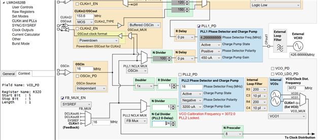
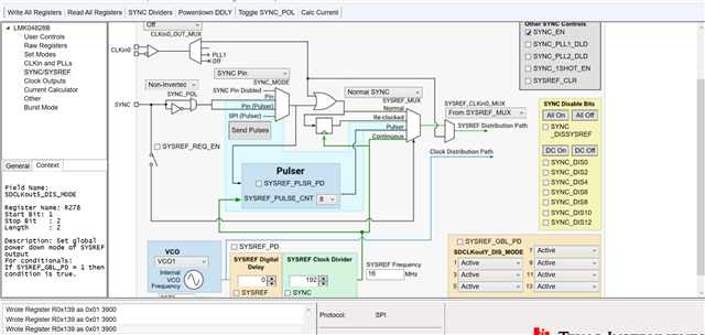
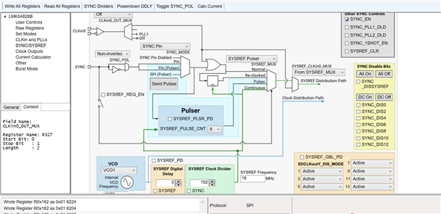
PLL 端的配置看起来正确。 在 SYSREF 页面上,复查 SYSREF 是否已启用并配置为192分频 ,并复查 N 分频器是否在N cal divider编程后进行编程。 或者,尝试重置设备,方法是在“User Controls”页面上切换RESET bit 0 -> 1 -> 0,然后使用 Ctrl-L 或顶部菜单栏的 USB communications选项卡中的选项writing all registers。 如果这仍然不起作用,您可以从Other页的选项中将相位探测器的 R 和 N 输入信号从 Status_LDx 引脚中移出, 并使用示波器进行探查,以确定参考和反馈路径是否有信号,频率是否正确和稳定等
原文“Most likely the PLL is not stable with 16MHz phase detector, if you are using default EVM loop filter values. I checked the default loop filter values usingPLLatinum Sim, and I found that the loop phase margin is only 40° which is probably too low. You may need to calculate stable loop filter values first - try targeting a loop bandwidth of 50kHz in PLLatinum Sim with LMK04828B VCO1 device and your configuration.
The configuration looks correct on the PLL side. Double check that the SYSREF divider is enabled and configured for divide-by-192 on theSYNC/SYSREFpage, and double-check that the N-divider is being programmed after the N cal divider is programmed. Alternately, try resetting the device by toggling the RESET bit 0 -> 1 -> 0 on theUser Controlspage, then writing all registers using Ctrl-L or the option in USB communications tab on top menu bar. If that still doesn't work, you can bring the signal at the R and N inputs to the phase detector out of the Status_LDx pins from the options on theOtherpage, and probe with an oscilloscope to identify whether the reference and feedback paths have signal, whether the frequencies are correct and stable, etc.”