If you have a related question, please click the "Ask a related question" button in the top right corner. The newly created question will be automatically linked to this question.
Zero dark time external pattern display for illumination time less than 400 uSec
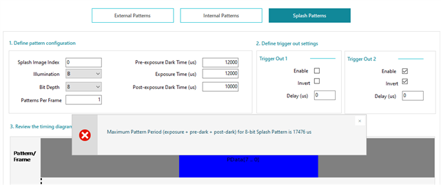
Splash Patterns (Mono 1 Bit/ 8 Bit)
Display
External video input
IntelliBright video processing algorithms
Splash Screens
Source frame rates supported - 0 to 123 HZ
Four 2D looks (cool, medium, warm, and other) and one 3D look
Supported pattern timings in Sequence Database v0.5.71:
Internal Pattern Mode Timings:
Pattern Type
Sequence Index
Exposure Time Range (us)
Sequence Min Pre-Exposure Dark Time (us)
Sequence Min Post-Exposure Dark Time (us)
1-bit Monochrome
18
200 - 399
171
31
17
400 - 799
171
31
16
800 - 799
171
31
15
1800 - 3799
171
31
14
3800 - 7600
171
31
1-bit RGB
25
600 - 1799
171
31
24
1800 - 3799
171
31
23
3800 - 7600
171
31
8-bit Monochrome
20
3464 - 6928
171
31
21*
1677 - 3463
171
31
8-bit RGB
22
10912 - 21824
171
31
*Sequence 21 is a special sequence that displays 7-bit patterns. The least significant bit of the 8-bit pattern data will be ignored.
Notes:
For internal patterns, there will be an additional variable delay of ~3000 us at the beginning of every pattern set.
Exposure times shorter than the above values are not possible. Longer exposure times will operate with decreased timing accuracy and behavior is not guaranteed.
Shorter dark times are not possible. Longer dark times can be used. The maximum possible dark times for a desired exposure time are:
Tmax pre-exposure dark time = ( 27306us + tsequence min pre-exposure dark time ) * (Tdesired exposure / tsequence minimum exposure)
Tmax post-exposure dark time = ( 27306us + tsequence min post-exposure dark time ) * (Tdesired exposure / tsequence minimum exposure)
External Pattern Streaming Timings:
Pattern Type
Sequence Index
Exposure Time Range (us)
Sequence Min Pre-Exposure Dark Time (us)
Sequence Min Post-Exposure Dark Time (us)
1-bit Monochrome
6
200 - 400
0*
0*
5
200 - 399
171
31
4
400 - 799
171
31
3
800 - 1799
171
31
2
1800 - 3799
171
31
1
3800 - 7600
171
31
1-bit RGB
11
451 - 799
171
31
10
800 - 1799
171
31
9
1800 - 3799
171
31
8
3800 - 7600
171
31
8-bit Monochrome
7
2555 - 5110
171
31
8-bit RGB
0
10912 - 21824
171
31
*Sequence 6 is a special sequence with zero pre-exposure and post-exposure dark times. (Note: While running this sequence, a dark time equivalent to the exposure time of one pattern will be added at the start of every pattern set.)
Notes:
Exposure times shorter than the above values are not possible. Longer exposure times will operate with decreased timing accuracy and behavior is not guaranteed.
Shorter dark times are not possible. Longer dark times can be used. The maximum possible dark times for a desired exposure time are:
Tmax pre-exposure dark time = ( 6553us + tsequence min pre-exposure dark time ) * (Tdesired exposure / tsequence minimum exposure)
Tmax post-exposure dark time = ( 6553us + tsequence min post-exposure dark time ) * (Tdesired exposure / tsequence minimum exposure)
Splash Pattern Mode Timings:
Pattern Type
Sequence Index
Exposure Time Range (us)
Sequence Min Pre-Exposure Dark Time (us)
Sequence Min Post-Exposure Dark Time (us)
1 -bit Monochrome
13
793 - 1744
171
31
8-bit Monochrome
12
7737 - 17034
171
31
Notes:
The maximum pattern period (pre-exposure + exposure + post-exposure) cannot exceed 2184us for 1-bit splash patterns and 17476us for 8-bit splash patterns.
The listed minimum dark times are applicable for the minimum exposure time of each sequence. The dark times scale along with the exposure time as per the following equation:
Tmin required pre-exposure dark time = tsequence min pre-exposure dark time * (Tdesired exposure / tsequence minimum exposure)
Tmin required post-exposure dark time = tsequence min post-exposure dark time * (Tdesired exposure / tsequence minimum exposure)
I2C command 0x9D(Read Validate Exposure Time)returns the minimum required pre-exposure and post-exposure dark times for a specific pattern type and given exposure time.
Updates in this release
Firmware will support the systems with the Light Control DMDs (DLP2010LC, DLP3010LC) only.
Auto-idle mode is not supported.
Only DMD pin mapping options 1 and 2 are supported.
The corruption observed in internal pattern mode while running 200us zero dark time pattern sets has been fixed.
Patterns are only supported in RGB format (not YCbCr) when running in Splash Pattern mode.
Thermistor processing enabled by default
Known Limitations
Internal Patterns 8 bit RGB sequence - post dark time does not match specified value.
Non uniformity is seen at the display borders while running 1 bit internal patterns with 0 pre,post exposure times.
External Streaming - Signals/Patterns Incorrect in case of VSYNC jitter.
When switching from internal pattern mode to splash pattern mode make sure that the internal pattern display is stopped.
While using the update firmware feature of GUI, make sure that size of splash image are as small as possible and prefer selecting RGB color space if the images are of PNG format.
LC splash pattern dispaly is only supported in RGB format.
Only RGB888 input source format supported in External Pattern Streaming Mode.
Unsupported Features:
DSI/BT656 Input
CPU Interface
LABB with Ambient Light Sensor support
Shallow Gradient
White Point Correction
I2C at 400KHz
Flashless configuration
Idle mode
Power management, clock gating and scaling
CAIC is not supported in LC, system will not boot up in LC mode with CAIC enabled
Technical Support and Product Updates
Thermistor Processing Documentation
Using System Temperature via I2C commands:
Read System Temperature (0xd6)
Output: 2 Bytes
Byte 1: LSB
Byte 2: MSB
Note: The temperature of the thermistor is read in degrees Celsius in a magnitude of 10 times the reading of thermistor. Bit 11 (the most significant bit) denotes the sign temperature. A '0' means a positive temperature, while '1' denotes a negative temperature.
Example #1: b(11:0) = 000110101010; 426d / 10d = 42.6degC
Example #2: b(11:0) = 100110101010; 426d / 10d = -42.6degC
Note: This temperature reading will need to be calibrated per the design and specific thermsitor chosen of custom boards. Offset to determine the true temperature of the thermistor reading. Texas Instruments DLP hardware uses Murata's NCP15WF104F03RC.
TI is a global semiconductor design and manufacturing company. Innovate with 100,000+ analog ICs and embedded processors, along with software, tools and the industry‘s largest sales/support staff.