请注意,本文内容源自机器翻译,可能存在语法或其它翻译错误,仅供参考。如需获取准确内容,请参阅链接中的英语原文或自行翻译。
器件型号:TM4C1230E6PM 主题中讨论的其他器件:PCF8574
大家好、我遇到了 I2C 的 tivaware 命令问题。 我需要向安装在小型 PCA 上的 I2C 从设备(MCP23017 16位 IO 扩展器)发送两个字节的信息。 我已验证 PCA 是否可以与 Arduino 和示例代码一起正常工作。
根据 SPMA073、I2C_MASTER_CMD_BURST_SEND_START 应发送开始位、从器件地址、清除的写入位以及 I2CMDR 中通过 I2CMDataPut 输入的附加字节命令。 然后、可以使用 I2C_MASTER_CMD_BURST_SEND_FINISH 发送数据的第二个字节。 这基本上意味着以这种方式发送起始位、从地址、写入位和两个字节。
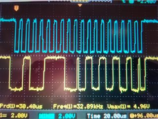
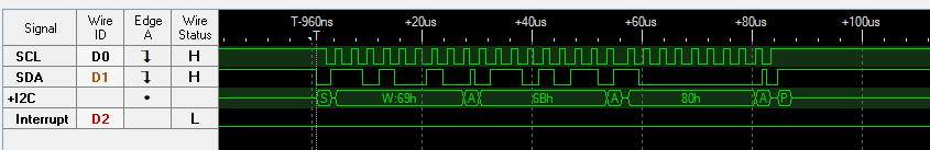
我的问题是 I2C_MASTER_CMD_BURST_SEND_START 似乎不发送在 I2CMDR 中输入的字节。 请参阅下面的代码以及随附的 I2C 在总线上发送的示波器截图。 如果我的代码不正确、或者对流程的工作方式有误解、请告知我。 感谢所有回复。
#include <__cross_studio_io.h>
#include <stdarg.h>
#include <stdbool.h>
#include <stdint.h>
#include <stdio.h>
#include "inc/hw_i2c.h"
#include "inc/hw_memmap.h"
#include "inc/hw_types.h"
#include "inc/hw_ints.h"
#include "driverlib/i2c.h"
#include "driverlib/interrupt.h"
#include "driverlib/sysctl.h"
#include "driverlib/timer.h"
#include "driverlib/gpio.h"
#include "driverlib/uart.h"
#include "driverlib/pin_map.h"
#include "driverlib/debug.h"
#include "driverlib/rom.h"

#ifdef DEBUG
void
__error__(char *pcFilename, uint32_t ui32Line)
{
}
#endif

uint8_t opcode = 0x27; //MCP23017 with A0 through A2 set as High

//initialize I2C module 5
void InitI2C5(void)
{

    //enable I2C module 0
    SysCtlPeripheralDisable(SYSCTL_PERIPH_I2C5);
    SysCtlPeripheralReset(SYSCTL_PERIPH_I2C5);
    SysCtlPeripheralEnable(SYSCTL_PERIPH_I2C5);

    while(!SysCtlPeripheralReady(SYSCTL_PERIPH_I2C5));

    // Enable and initialize the I2C5 master module.  Use the system clock for
    // the I2C5 module.  The last parameter sets the I2C data transfer rate.
    // If false the data rate is set to 100kbps and if true the data rate will
    // be set to 400kbps.
    I2CMasterInitExpClk(I2C5_BASE, SysCtlClockGet(), false);

    //enable GPIO peripheral that contains I2C 5
    SysCtlPeripheralEnable(SYSCTL_PERIPH_GPIOB);

    // Configure the pin muxing for I2C5 functions on port B6 and B7.
    GPIOPinConfigure(GPIO_PB6_I2C5SCL);
    GPIOPinConfigure(GPIO_PB7_I2C5SDA);

    // Select the I2C function for these pins.
    GPIOPinTypeI2CSCL(GPIO_PORTB_BASE, GPIO_PIN_6);
    GPIOPinTypeI2C(GPIO_PORTB_BASE, GPIO_PIN_7);

    SysCtlPeripheralEnable(SYSCTL_PERIPH_GPIOC);
    SysCtlDelay(1);
    //
    // Configure LED pins as outputs.
    //
    GPIOPinTypeGPIOOutput(GPIO_PORTC_BASE, GPIO_PIN_5 | GPIO_PIN_6);

}

void main(void)
{
    // Set the clocking to run directly from the external crystal/oscillator.
     SysCtlClockSet(SYSCTL_SYSDIV_4 | SYSCTL_USE_PLL | SYSCTL_XTAL_16MHZ | SYSCTL_OSC_MAIN);

    //initialize I2C module 5
    InitI2C5();

     //Turn I2C power on.
     GPIOPinWrite(GPIO_PORTC_BASE, GPIO_PIN_5, GPIO_PIN_5);

    while(1)
    {
     //Turn Red LED on.
     //GPIOPinWrite(GPIO_PORTC_BASE, GPIO_PIN_6, GPIO_PIN_6);

     SysCtlDelay(5000000);

        // Wait until MCU is done transferring.
        while(I2CMasterBusBusy(I2C5_BASE)) {}

         // Tell the master module what address it will place on the bus when
         // communicating with the slave.
        I2CMasterSlaveAddrSet(I2C5_BASE, opcode, false);

//-------------------------------------------------------------------
         //Configure MCP23017 IODIRB output pins
         //put data to be sent into FIFO
         I2CMasterDataPut(I2C5_BASE, 0x13);

         //Initiate send of data from the MCU
        I2CMasterControl(I2C5_BASE, I2C_MASTER_CMD_BURST_SEND_START);

        // Wait until MCU is done transferring.
        while(I2CMasterBusBusy(I2C5_BASE)) {}

        //Check for errors
        if (I2CMasterErr(I2C5_BASE) != I2C_MASTER_ERR_NONE)
          {
            //Turn Red LED on.
	    GPIOPinWrite(GPIO_PORTC_BASE, GPIO_PIN_5, GPIO_PIN_5);
          }

         //put data to be sent into FIFO
         I2CMasterDataPut(I2C5_BASE, 0x55);

         //Initiate send of data from the MCU
        I2CMasterControl(I2C5_BASE, I2C_MASTER_CMD_BURST_SEND_FINISH);

        // Wait until MCU is done transferring.
        while(I2CMasterBusBusy(I2C5_BASE)) {}

        //Check for errors
        if (I2CMasterErr(I2C5_BASE) != I2C_MASTER_ERR_NONE)
          {
            //Turn Red LED on.
	    GPIOPinWrite(GPIO_PORTC_BASE, GPIO_PIN_5, GPIO_PIN_5);
          }
//-------------------------------------------------------------------

     //Turn Red LED off.
     //GPIOPinWrite(GPIO_PORTC_BASE, GPIO_PIN_6, 0);

     SysCtlDelay(5000000);

    }
}