This thread has been locked.

If you have a related question, please click the "Ask a related question" button in the top right corner. The newly created question will be automatically linked to this question.

[参考译文] LAUNCHXL-F28069M:SCI:通过 Motorware 驱动程序传输数据

Guru**** 649970 points
Other Parts Discussed in Thread: MOTORWARE
请注意,本文内容源自机器翻译,可能存在语法或其它翻译错误,仅供参考。如需获取准确内容,请参阅链接中的英语原文或自行翻译。

https://e2e.ti.com/support/microcontrollers/c2000-microcontrollers-group/c2000/f/c2000-microcontrollers-forum/1122436/launchxl-f28069m-sci-transmit-data-through-motorware-drivers

器件型号:LAUNCHXL-F28069M
主题中讨论的其他器件:MOTORWARE

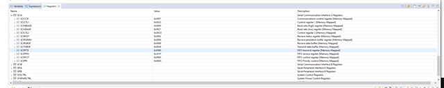
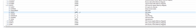
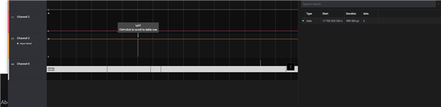
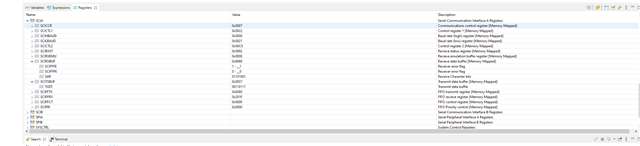
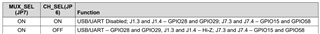
我从 SCI 回送的一个简单示例  example_2806xSci_Echoback.c 开始、能够修改代码、反复输出文本并通过我的逻辑分析仪进行查看。   现在、我正在尝试通过 instaspin lab10d 中的 sci.c 启用和使用 TX 和 Rx 引脚。   当我输入代码执行此操作时、我没有看到任何数据随逻辑分析仪发出。  本实验还会切换 LED。 因此、为了进行完整性检查、我尝试查看是否可以关闭其中一个 LED。   因此、在 proj_lab10d.c 中、我在第463行注释了代码、并将这一行代码和其他几行代码放在第230-232行、运气不佳。  灯一直亮着。  因此、我很难完成我要做的事情。  在  Example_2806xSci_Echoback 中 、gpio29引用了 j1.4引脚。    instaspin 实验 gpio.h 中的 GPIO_Number_29 是否引用同一个 j1.4引脚?   或者我可能没有在我的 sci 代码中启用某项功能。  我出了什么问题?  简单的切换功能调用为什么不会关闭灯?  但是、当它处于无限循环中时、它会打开和关闭它?   

我在 proj_lab10d.c 中启用 sci 的代码来自第218-261行、然后我尝试在第439行发送数据。    

proj_lab10d.c

/* --COPYRIGHT--,BSD
 * Copyright (c) 2012, Texas Instruments Incorporated
 * All rights reserved.
 *
 * Redistribution and use in source and binary forms, with or without
 * modification, are permitted provided that the following conditions
 * are met:
 *
 * *  Redistributions of source code must retain the above copyright
 *    notice, this list of conditions and the following disclaimer.
 *
 * *  Redistributions in binary form must reproduce the above copyright
 *    notice, this list of conditions and the following disclaimer in the
 *    documentation and/or other materials provided with the distribution.
 *
 * *  Neither the name of Texas Instruments Incorporated nor the names of
 *    its contributors may be used to endorse or promote products derived
 *    from this software without specific prior written permission.
 *
 * THIS SOFTWARE IS PROVIDED BY THE COPYRIGHT HOLDERS AND CONTRIBUTORS "AS IS"
 * AND ANY EXPRESS OR IMPLIED WARRANTIES, INCLUDING, BUT NOT LIMITED TO,
 * THE IMPLIED WARRANTIES OF MERCHANTABILITY AND FITNESS FOR A PARTICULAR
 * PURPOSE ARE DISCLAIMED. IN NO EVENT SHALL THE COPYRIGHT OWNER OR
 * CONTRIBUTORS BE LIABLE FOR ANY DIRECT, INDIRECT, INCIDENTAL, SPECIAL,
 * EXEMPLARY, OR CONSEQUENTIAL DAMAGES (INCLUDING, BUT NOT LIMITED TO,
 * PROCUREMENT OF SUBSTITUTE GOODS OR SERVICES; LOSS OF USE, DATA, OR PROFITS;
 * OR BUSINESS INTERRUPTION) HOWEVER CAUSED AND ON ANY THEORY OF LIABILITY,
 * WHETHER IN CONTRACT, STRICT LIABILITY, OR TORT (INCLUDING NEGLIGENCE OR
 * OTHERWISE) ARISING IN ANY WAY OUT OF THE USE OF THIS SOFTWARE,
 * EVEN IF ADVISED OF THE POSSIBILITY OF SUCH DAMAGE.
 * --/COPYRIGHT--*/
//! \file   solutions/instaspin_foc/src/proj_lab10d.c
//! \brief Dual motor project
//!
//! (C) Copyright 2011, Texas Instruments, Inc.

//! \defgroup PROJ_LAB10d PROJ_LAB10d
//@{

//! \defgroup PROJ_LAB10d_OVERVIEW Project Overview
//!
//! Dual Motor Sensorless Velocity Control
//!

// **************************************************************************
// the includes

// system includes
#include <math.h>
#include "main_2motors.h"

#ifdef FLASH
#pragma CODE_SECTION(motor1_ISR,"ramfuncs");
#pragma CODE_SECTION(motor2_ISR,"ramfuncs");
#endif

// Include header files used in the main function


// **************************************************************************
// the defines

#define LED_BLINK_FREQ_Hz   5

#define EST_Number1         0
#define CTRL_Number1        0

//#define _ENABLE_OVM_
// **************************************************************************
// the globals
CTRL_Handle ctrlHandle[2];

uint_least16_t gCounter_updateGlobals[2] = {0, 0};
uint_least8_t motorNum = 0;
uint_least8_t estNumber[2] = {0, 1};
uint_least8_t ctrlNumber[2] = {0, 1};

bool Flag_Latch_softwareUpdate[2] = {true, true};


#ifdef CSM_ENABLE
#pragma DATA_SECTION(halHandle,"rom_accessed_data");
#endif

HAL_Handle halHandle;

#ifdef CSM_ENABLE
#pragma DATA_SECTION(gUserParams,"rom_accessed_data");
#endif

USER_Params gUserParams[2];

// the pwm voltage values for the three phases.
HAL_PwmData_t gPwmData[2] = {{_IQ(0.0), _IQ(0.0), _IQ(0.0)}, {_IQ(0.0), _IQ(0.0), _IQ(0.0)}};

// the voltage and current adc values for the CTRL controller and the FAST estimator.
HAL_AdcData_t gAdcData[2];

// the PWMDAC variable
HAL_DacData_t gDacData;

_iq gMaxCurrentSlope[2] = {_IQ(0.0), _IQ(0.0)};

#ifdef FAST_ROM_V1p6
CTRL_Obj *controller_obj[2];
#else
#ifdef CSM_ENABLE
#pragma DATA_SECTION(ctrl,"rom_accessed_data");
#endif
CTRL_Obj ctrl[2];               //v1p7 format
#endif

uint16_t gLEDcnt[2] = {0, 0};

// the variables to turn on and adjust InstaSPIN
volatile MOTOR_Vars_t gMotorVars[2] = {MOTOR_Vars_INIT_Mtr1,MOTOR_Vars_INIT_Mtr2};

//
volatile SYSTEM_Vars_t gSystemVars = SYSTEM_Vars_INIT;

#ifdef FLASH
// Used for running BackGround in flash, and ISR in RAM
extern uint16_t *RamfuncsLoadStart, *RamfuncsLoadEnd, *RamfuncsRunStart;

#ifdef CSM_ENABLE
extern uint16_t *econst_start, *econst_end, *econst_ram_load;
extern uint16_t *switch_start, *switch_end, *switch_ram_load;
#endif
#endif

SVGENCURRENT_Obj svgencurrent[2];
SVGENCURRENT_Handle svgencurrentHandle[2];

// set the offset, default value of 1 microsecond
int16_t gCmpOffset[2] = {(int16_t)(1.0 * USER_SYSTEM_FREQ_MHz_M1), (int16_t)(1.0 * USER_SYSTEM_FREQ_MHz_M2)};

MATH_vec3 gIavg[2] = {{_IQ(0.0), _IQ(0.0), _IQ(0.0)}, {_IQ(0.0), _IQ(0.0), _IQ(0.0)}};
uint16_t gIavg_shift[2] = {1, 1};
MATH_vec3 gPwmData_prev[2] = {{_IQ(0.0), _IQ(0.0), _IQ(0.0)}, {_IQ(0.0), _IQ(0.0), _IQ(0.0)}};

#ifdef DRV8301_SPI
// Watch window interface to the 8301 SPI
DRV_SPI_8301_Vars_t gDrvSpi8301Vars[2];
#endif

#ifdef DRV8305_SPI
// Watch window interface to the 8305 SPI
DRV_SPI_8305_Vars_t gDrvSpi8305Vars[2];
#endif

_iq gFlux_pu_to_Wb_sf[2];

_iq gFlux_pu_to_VpHz_sf[2];

_iq gTorque_Ls_Id_Iq_pu_to_Nm_sf[2];

_iq gTorque_Flux_Iq_pu_to_Nm_sf[2];

HAL_Handle      halHandle;          //!< the handle for the hardware abstraction
                                     //!< layer for common CPU setup
HAL_Obj         hal;                //!< the hardware abstraction layer object

#ifdef F2802xF
#pragma DATA_SECTION(halHandleMtr,"rom_accessed_data");
#endif

HAL_Handle_mtr  halHandleMtr[2];    //!< the handle for the hardware abstraction
                                     //!< layer specific to the motor board.
HAL_Obj_mtr     halMtr[2];          //!< the hardware abstraction layer object
                                     //!< specific to the motor board.

// define Flying Start (FS) variables
FS_Obj fs[2];
FS_Handle fsHandle[2];

// define cpu_time object and handle for CPU usage time calculation
CPU_TIME_Handle  cpu_timeHandle[2];
CPU_TIME_Obj     cpu_time[2];

// **************************************************************************
// the functions
float motorSpeed = 0.2;

void main(void)
{
  // Only used if running from FLASH
  // Note that the variable FLASH is defined by the project
  #ifdef FLASH
  // Copy time critical code and Flash setup code to RAM
  // The RamfuncsLoadStart, RamfuncsLoadEnd, and RamfuncsRunStart
  // symbols are created by the linker. Refer to the linker files.
  memCopy((uint16_t *)&RamfuncsLoadStart,(uint16_t *)&RamfuncsLoadEnd,(uint16_t *)&RamfuncsRunStart);

  #ifdef CSM_ENABLE
  //copy .econst to unsecure RAM
  if(*econst_end - *econst_start)
    {
      memCopy((uint16_t *)&econst_start,(uint16_t *)&econst_end,(uint16_t *)&econst_ram_load);
    }

  //copy .switch ot unsecure RAM
  if(*switch_end - *switch_start)
    {
      memCopy((uint16_t *)&switch_start,(uint16_t *)&switch_end,(uint16_t *)&switch_ram_load);
    }
  #endif
  #endif


  // initialize the hardware abstraction layer
  halHandle = HAL_init(&hal,sizeof(hal));


  /*
   *   TESTING GPIO FOR UART OF GPIO28 AND GPIO29
   */

    HAL_Obj *obj = (HAL_Obj *)halHandle;

    // Set pullups
    GPIO_setPullup(obj->gpioHandle, GPIO_Number_28, GPIO_Pullup_Enable);
    GPIO_setPullup(obj->gpioHandle, GPIO_Number_29, GPIO_Pullup_Enable);

    // Set gpio 28 as async input and as SCIRXDA
    GPIO_setQualification(obj->gpioHandle, GPIO_Number_28, GPIO_Qual_ASync);
    GPIO_setMode(obj->gpioHandle, GPIO_Number_28, GPIO_28_Mode_SCIRXDA);

   // Set gpio 29 as SCITXDA
   GPIO_setMode(obj->gpioHandle, GPIO_Number_29, GPIO_29_Mode_SCITXDA);
//   GPIO_setLow(obj->gpioHandle, (GPIO_Number_e)HAL_Gpio_LED2)
//   GPIO_toggle(obj->gpioHandle, (GPIO_Number_e)HAL_Gpio_LED2);
//     HAL_toggleLed(halHandle,(GPIO_Number_e)HAL_Gpio_LED2);

    // Enable fifo
    SCI_enableRxFifo(obj->sciHandle);
    SCI_enableTxFifo(obj->sciHandle);

    /*
     *  1 stop bit,  No loopback, No parity,8 char bits, async mode,
     *   idle-line protocol
     */
    SCI_setNumStopBits(obj->sciHandle, SCI_NumStopBits_One);
    SCI_disableParity(obj->sciHandle);
    SCI_setCharLength(obj->sciHandle, SCI_CharLength_8_Bits);
    SCI_setMode(obj->sciHandle, SCI_Mode_IdleLine);

    /*
     * enable TX, RX, internal SCICLK, Disable RX ERR, SLEEP, TXWAKE
     */
    SCI_enableTx(obj->sciHandle);
    SCI_enableRx(obj->sciHandle);
    SCI_disableRxErrorInt(obj->sciHandle);
    SCI_disableSleep(obj->sciHandle);
    SCI_disableTxWake(obj->sciHandle);

    // Set baud
    SCI_setBaudRate(obj->sciHandle, SCI_BaudRate_57_6_kBaud);

  /*
   *  -------------------------------------------
   */

  // initialize the individual motor hal files
  halHandleMtr[HAL_MTR1] = HAL_init_mtr(&halMtr[HAL_MTR1], sizeof(halMtr[HAL_MTR1]), (HAL_MtrSelect_e)HAL_MTR1);

  // initialize the individual motor hal files
  halHandleMtr[HAL_MTR2] = HAL_init_mtr(&halMtr[HAL_MTR2], sizeof(halMtr[HAL_MTR2]), (HAL_MtrSelect_e)HAL_MTR2);

  // initialize the controller
    #ifdef FAST_ROM_V1p6
    //  ctrlHandle[HAL_MTR1] = CTRL_initCtrl(CTRL_Number1, EST_Number1);        //v1p6 format (06xF and 06xM devices)
      ctrlHandle[HAL_MTR1] = CTRL_initCtrl(ctrlNumber[HAL_MTR1], estNumber[HAL_MTR1]);                      //v1p6 format (06xF and 06xM devices)
      ctrlHandle[HAL_MTR2] = CTRL_initCtrl(ctrlNumber[HAL_MTR2], estNumber[HAL_MTR2]);                      //v1p6 format (06xF and 06xM devices)
    #else
      ctrlHandle[HAL_MTR1] = CTRL_initCtrl(estNumber[HAL_MTR1], &ctrl[HAL_MTR1], sizeof(ctrl[HAL_MTR1]));   //v1p7 format default
      ctrlHandle[HAL_MTR2] = CTRL_initCtrl(estNumber[HAL_MTR2], &ctrl[HAL_MTR2], sizeof(ctrl[HAL_MTR2]));   //v1p7 format default
    #endif

  // Initialize and setup the 100% SVM generator
  svgencurrentHandle[HAL_MTR1] = SVGENCURRENT_init(&svgencurrent[HAL_MTR1],sizeof(svgencurrent[HAL_MTR1]));

  // Initialize and setup the 100% SVM generator
  svgencurrentHandle[HAL_MTR2] = SVGENCURRENT_init(&svgencurrent[HAL_MTR2],sizeof(svgencurrent[HAL_MTR2]));

  // initialize the user parameters
  // This function initializes all values of structure gUserParams with
  // values defined in user.h. The values in gUserParams will be then used by
  // the hardware abstraction layer (HAL) to configure peripherals such as
  // PWM, ADC, interrupts, etc.
  USER_setParamsMtr1(&gUserParams[HAL_MTR1]);
  USER_setParamsMtr2(&gUserParams[HAL_MTR2]);

  //HAL_setParams
  // set the common hardware abstraction layer parameters
  HAL_setParams(halHandle,&gUserParams[HAL_MTR1]);

  #ifdef _SINGLE_ISR_EN_
  // Setup each motor board to its specific setting
  HAL_setParamsDualMtr(halHandleMtr[HAL_MTR1], halHandleMtr[HAL_MTR2], halHandle, &gUserParams[HAL_MTR1], &gUserParams[HAL_MTR2]);
  #else
  // Setup each motor board to its specific setting
  HAL_setParamsMtr(halHandleMtr[HAL_MTR1],halHandle, &gUserParams[HAL_MTR1]);

  // Setup each motor board to its specific setting
  HAL_setParamsMtr(halHandleMtr[HAL_MTR2],halHandle, &gUserParams[HAL_MTR2]);
  #endif


  //TURN ON GLOBAL SYSTEM AND M
  gSystemVars.Flag_enableSystem = 1;
  gMotorVars[HAL_MTR1].Flag_Run_Identify = 1;
  gMotorVars[HAL_MTR1].Flag_enableUserParams = true;

  gMotorVars[HAL_MTR2].Flag_enableUserParams = true;

  gMotorVars[HAL_MTR1].Flag_enableSpeedCtrl = true;
  gMotorVars[HAL_MTR2].Flag_enableSpeedCtrl = true;

  for(motorNum=HAL_MTR1;motorNum<=HAL_MTR2;motorNum++)
  {
      // set the default controller parameters
      CTRL_setParams(ctrlHandle[motorNum], &gUserParams[motorNum]);

      // set the default controller parameters (Reset the control to re-identify the motor)
      CTRL_setParams(ctrlHandle[motorNum],&gUserParams[motorNum]);

      {
        // initialize the CPU usage module
        cpu_timeHandle[motorNum] = CPU_TIME_init(&cpu_time[motorNum],sizeof(cpu_time[motorNum]));
        CPU_TIME_setParams(cpu_timeHandle[motorNum], PWM_getPeriod(halHandleMtr[motorNum]->pwmHandle[0]));
      }

      // set overmodulation to maximum value
      gMotorVars[motorNum].OverModulation = _IQ(MATH_TWO_OVER_THREE);

      // setup faults
      HAL_setupFaults(halHandleMtr[motorNum]);

      // enable DC bus compensation
      CTRL_setFlag_enableDcBusComp(ctrlHandle[motorNum], true);

      // compute scaling factors for flux and torque calculations
      gFlux_pu_to_Wb_sf[motorNum] = USER_computeFlux_pu_to_Wb_sf(&gUserParams[motorNum]);
      gFlux_pu_to_VpHz_sf[motorNum] = USER_computeFlux_pu_to_VpHz_sf(&gUserParams[motorNum]);
      gTorque_Ls_Id_Iq_pu_to_Nm_sf[motorNum] = USER_computeTorque_Ls_Id_Iq_pu_to_Nm_sf(&gUserParams[motorNum]);
      gTorque_Flux_Iq_pu_to_Nm_sf[motorNum] = USER_computeTorque_Flux_Iq_pu_to_Nm_sf(&gUserParams[motorNum]);

      gMotorVars[motorNum].current_pu_to_A_sf = _IQ(gUserParams[motorNum].iqFullScaleCurrent_A);
      gMotorVars[motorNum].voltage_pu_to_kv_sf = _IQ(gUserParams[motorNum].iqFullScaleVoltage_V/(float_t)1000.0);
      gMotorVars[motorNum].current_A_to_pu_sf = _IQdiv(_IQ(1.0), gMotorVars[motorNum].current_pu_to_A_sf);

    #ifdef DRV8301_SPI
      // turn on the DRV8301 if present
      HAL_enableDrv(halHandleMtr[motorNum]);
      // initialize the DRV8301 interface
      HAL_setupDrvSpi(halHandleMtr[motorNum],&gDrvSpi8301Vars[motorNum]);
    #endif

    #ifdef DRV8305_SPI
      // turn on the DRV8305 if present
      HAL_enableDrv(halHandleMtr[motorNum]);
      // initialize the DRV8305 interface
      HAL_setupDrvSpi(halHandleMtr[motorNum],&gDrvSpi8305Vars[motorNum]);
    #endif

      gCounter_updateGlobals[motorNum] = 0;
  }

  // setup svgen current for Motor #1
  {
    float_t minWidth_microseconds_M1 = 2.0;
    uint16_t minWidth_counts = (uint16_t)(minWidth_microseconds_M1 * USER_SYSTEM_FREQ_MHz);
    float_t fdutyLimit = 0.5-(2.0*minWidth_microseconds_M1*USER_PWM_FREQ_kHz_M1*0.001);
    _iq dutyLimit = _IQ(fdutyLimit);

    SVGENCURRENT_setMinWidth(svgencurrentHandle[HAL_MTR1], minWidth_counts);
    SVGENCURRENT_setIgnoreShunt(svgencurrentHandle[HAL_MTR1], use_all);
    SVGENCURRENT_setMode(svgencurrentHandle[HAL_MTR1],all_phase_measurable);
    SVGENCURRENT_setVlimit(svgencurrentHandle[HAL_MTR1],dutyLimit);
  }

  // setup svgen current for Motor #2
  {
    float_t minWidth_microseconds_M2 = 2.0;
    uint16_t minWidth_counts = (uint16_t)(minWidth_microseconds_M2 * USER_SYSTEM_FREQ_MHz);
    float_t fdutyLimit = 0.5-(2.0*minWidth_microseconds_M2*USER_PWM_FREQ_kHz_M2*0.001);
    _iq dutyLimit = _IQ(fdutyLimit);

    SVGENCURRENT_setMinWidth(svgencurrentHandle[HAL_MTR2], minWidth_counts);
    SVGENCURRENT_setIgnoreShunt(svgencurrentHandle[HAL_MTR2], use_all);
    SVGENCURRENT_setMode(svgencurrentHandle[HAL_MTR2],all_phase_measurable);
    SVGENCURRENT_setVlimit(svgencurrentHandle[HAL_MTR2],dutyLimit);
  }

  {
    CTRL_Version version;

    // get the version number
    CTRL_getVersion(ctrlHandle[HAL_MTR1],&version);

    gMotorVars[HAL_MTR1].CtrlVersion = version;
    gMotorVars[HAL_MTR2].CtrlVersion = version;
  }

  // set DAC parameters
  HAL_setDacParameters(halHandle, &gDacData);

  // initialize the interrupt vector table
  HAL_initIntVectorTable(halHandle);


  // enable the ADC interrupts
  HAL_enableAdcInts(halHandle);


  // enable global interrupts
  HAL_enableGlobalInts(halHandle);


  // enable debug interrupts
  HAL_enableDebugInt(halHandle);


  // disable the PWM
  HAL_disablePwm(halHandleMtr[HAL_MTR1]);
  HAL_disablePwm(halHandleMtr[HAL_MTR2]);


  // Below two lines code for Flash Testing, need to be commented
//  gSystemVars.Flag_enableSynControl = true;
//  gSystemVars.Flag_enableRun = true;

  for(;;)
    {

      /*
       *   ADDED CODE TO SEND DATA
       */
      SCI_putDataNonBlocking(obj->sciHandle, 72);
      /*
       * -------------------------
       */

      // Waiting for enable system flag to be set
      // Motor 1 Flag_enableSys is the master control.
  //    while(!(gMotorVars[HAL_MTR1].Flag_enableSys));
      while(!(gSystemVars.Flag_enableSystem));

      // Enable the Library internal PI.  Iq is referenced by the speed PI now
  //    CTRL_setFlag_enableSpeedCtrl(ctrlHandle[HAL_MTR1], true);

      // Enable the Library internal PI.  Iq is referenced by the speed PI now
  //    CTRL_setFlag_enableSpeedCtrl(ctrlHandle[HAL_MTR2], true);

      // loop while the enable system flag is true
      // Motor 1 Flag_enableSys is the master control.
  //    while(gMotorVars[HAL_MTR1].Flag_enableSys)
      while(gSystemVars.Flag_enableSystem)
      {
          // toggle status LED
          if(gLEDcnt[HAL_MTR1]++ > (uint_least32_t)(USER_ISR_FREQ_Hz_M1 / LED_BLINK_FREQ_Hz))
          {
//              HAL_toggleLed(halHandle,(GPIO_Number_e)HAL_Gpio_LED2);
              gLEDcnt[HAL_MTR1] = 0;
          }

          // toggle status LED
          if(gLEDcnt[HAL_MTR2]++ > (uint_least32_t)(USER_ISR_FREQ_Hz_M2 / LED_BLINK_FREQ_Hz))
          {
              HAL_toggleLed(halHandle,(GPIO_Number_e)HAL_Gpio_LED3);
              gLEDcnt[HAL_MTR2] = 0;
          }

//          if(gSystemVars.Flag_enableSynControl == true)
//          {
              gMotorVars[HAL_MTR1].Flag_Run_Identify = 1;
  //          gMotorVars[HAL_MTR1].SpeedRef_krpm = gSystemVars.SpeedSet_krpm;
              gMotorVars[HAL_MTR1].SpeedRef_krpm = _IQ(motorSpeed);
              gMotorVars[HAL_MTR1].MaxAccel_krpmps = _IQ(0.8);

              gMotorVars[HAL_MTR2].Flag_Run_Identify = gSystemVars.Flag_enableRun;
              gMotorVars[HAL_MTR2].SpeedRef_krpm = gSystemVars.SpeedSet_krpm;
              gMotorVars[HAL_MTR2].MaxAccel_krpmps = gSystemVars.MaxAccelSet_krpmps;
//          }

          for(motorNum=HAL_MTR1;motorNum<=HAL_MTR2;motorNum++)
          {
              CTRL_Obj *obj = (CTRL_Obj *)ctrlHandle[motorNum];

              // increment counters
              gCounter_updateGlobals[motorNum]++;

              if(CTRL_isError(ctrlHandle[motorNum]))
              {
                  // set the enable controller flag to false
                  CTRL_setFlag_enableCtrl(ctrlHandle[motorNum],false);

                  // set the enable system flag to false
                  gMotorVars[motorNum].Flag_enableSys = false;

                  // disable the PWM
                  HAL_disablePwm(halHandleMtr[motorNum]);
              }
              else
              {
                  // update the controller state
                  bool flag_ctrlStateChanged = CTRL_updateState(ctrlHandle[motorNum]);

                  // enable or disable the control
                  CTRL_setFlag_enableCtrl(ctrlHandle[motorNum], gMotorVars[motorNum].Flag_Run_Identify);

                  if(flag_ctrlStateChanged)
                  {
                      CTRL_State_e ctrlState = CTRL_getState(ctrlHandle[motorNum]);
                      EST_State_e estState = EST_getState(obj->estHandle);

                      if(ctrlState == CTRL_State_OffLine)
                      {
                          // enable the PWM
                          HAL_enablePwm(halHandleMtr[motorNum]);
                      }
                      else if(ctrlState == CTRL_State_OnLine)
                      {
  //                      if(gMotorVars[motorNum].Flag_enableOffsetcalc == true)
  //                      {
  //                          // update the ADC bias values
  //                          HAL_updateAdcBias(halHandleMtr[motorNum]);
  //                      }
  //                      else
  //                      {
  //                          // set the current bias
  //                          HAL_setBias(halHandleMtr[motorNum],HAL_SensorType_Current,0,_IQ(I_A_offset));
  //                          HAL_setBias(halHandleMtr[motorNum],HAL_SensorType_Current,1,_IQ(I_B_offset));
  //                          HAL_setBias(halHandleMtr[motorNum],HAL_SensorType_Current,2,_IQ(I_C_offset));
  //
  //                          // set the voltage bias
  //                          HAL_setBias(halHandleMtr[motorNum],HAL_SensorType_Voltage,0,_IQ(V_A_offset));
  //                          HAL_setBias(halHandleMtr[motorNum],HAL_SensorType_Voltage,1,_IQ(V_B_offset));
  //                          HAL_setBias(halHandleMtr[motorNum],HAL_SensorType_Voltage,2,_IQ(V_C_offset));
  //                      }

                          if((estState < EST_State_LockRotor) || (estState > EST_State_MotorIdentified))
                          {
                              // update the ADC bias values
                              HAL_updateAdcBias(halHandleMtr[motorNum]);
                          }

                          // Return the bias value for currents
                          gMotorVars[motorNum].I_bias.value[0] = HAL_getBias(halHandleMtr[motorNum],HAL_SensorType_Current,0);
                          gMotorVars[motorNum].I_bias.value[1] = HAL_getBias(halHandleMtr[motorNum],HAL_SensorType_Current,1);
                          gMotorVars[motorNum].I_bias.value[2] = HAL_getBias(halHandleMtr[motorNum],HAL_SensorType_Current,2);

                          // Return the bias value for voltages
                          gMotorVars[motorNum].V_bias.value[0] = HAL_getBias(halHandleMtr[motorNum],HAL_SensorType_Voltage,0);
                          gMotorVars[motorNum].V_bias.value[1] = HAL_getBias(halHandleMtr[motorNum],HAL_SensorType_Voltage,1);
                          gMotorVars[motorNum].V_bias.value[2] = HAL_getBias(halHandleMtr[motorNum],HAL_SensorType_Voltage,2);

                          // enable the PWM
                          HAL_enablePwm(halHandleMtr[motorNum]);
                      }
                      else if(ctrlState == CTRL_State_Idle)
                      {
                          // disable the PWM
                          HAL_disablePwm(halHandleMtr[motorNum]);
                          gMotorVars[motorNum].Flag_Run_Identify = false;
                      }       // ctrlState=?

                      if((CTRL_getFlag_enableUserMotorParams(ctrlHandle[motorNum]) == true) &&
                                                            (ctrlState > CTRL_State_Idle) &&
                                                    (gMotorVars[motorNum].CtrlVersion.minor == 6))
                      {
                          // call this function to fix 1p6
                          USER_softwareUpdate1p6(ctrlHandle[motorNum], &gUserParams[motorNum]);
                      }

                  }   // flag_ctrlStateChanged=?
              }   // CTRL_isError=?


              if(EST_isMotorIdentified(obj->estHandle))
              {
                  _iq Id_squared_pu = _IQmpy(CTRL_getId_ref_pu(ctrlHandle[motorNum]),CTRL_getId_ref_pu(ctrlHandle[motorNum]));

                  //Set the maximum current controller output for the Iq and Id current controllers to enable
                  //over-modulation.
                  //An input into the SVM above 1/SQRT(3) = 0.5774 is in the over-modulation region.  An input of 0.5774 is where
                  //the crest of the sinewave touches the 100% duty cycle.  At an input of 2/3, the SVM generator
                  //produces a trapezoidal waveform touching every corner of the hexagon
                  CTRL_setMaxVsMag_pu(ctrlHandle[motorNum],gMotorVars[motorNum].OverModulation);

                  // set the current ramp
                  EST_setMaxCurrentSlope_pu(obj->estHandle,gMaxCurrentSlope[motorNum]);

                  gMotorVars[motorNum].Flag_MotorIdentified = true;

                  // set the speed reference
                  CTRL_setSpd_ref_krpm(ctrlHandle[motorNum],gMotorVars[motorNum].SpeedRef_krpm);

                  // set the speed acceleration
  //              CTRL_setMaxAccel_pu(ctrlHandle[motorNum],_IQmpy(MAX_ACCEL_KRPMPS_SF_M1,gMotorVars[motorNum].MaxAccel_krpmps));
                  CTRL_setMaxAccel_pu(ctrlHandle[motorNum],_IQmpy(MAX_ACCEL_KRPMPS_SF_M1,gMotorVars[motorNum].MaxAccel_krpmps));

                  // set the Id reference
  //              CTRL_setId_ref_pu(ctrlHandle[motorNum], _IQmpy(gMotorVars.IdRef_A, _IQ(1.0/USER_IQ_FULL_SCALE_CURRENT_A)));
                  CTRL_setId_ref_pu(ctrlHandle[motorNum], _IQmpy(gMotorVars[motorNum].IdRef_A, gMotorVars[motorNum].current_A_to_pu_sf));

                  if(Flag_Latch_softwareUpdate[motorNum])
                  {
                    Flag_Latch_softwareUpdate[motorNum] = false;

                    USER_calcPIgains(ctrlHandle[motorNum], &gUserParams[motorNum]);

                    // initialize the watch window kp and ki current values with pre-calculated values
                    gMotorVars[motorNum].Kp_Idq = CTRL_getKp(ctrlHandle[motorNum],CTRL_Type_PID_Id);
                    gMotorVars[motorNum].Ki_Idq = CTRL_getKi(ctrlHandle[motorNum],CTRL_Type_PID_Id);

                    // initialize the watch window kp and ki current values with pre-calculated values
                    gMotorVars[motorNum].Kp_spd = CTRL_getKp(ctrlHandle[motorNum],CTRL_Type_PID_spd);
                    gMotorVars[motorNum].Ki_spd = CTRL_getKi(ctrlHandle[motorNum],CTRL_Type_PID_spd);
                  }
              }
              else
              {
                  Flag_Latch_softwareUpdate[motorNum] = true;

                  // initialize the watch window kp and ki values with pre-calculated values
  //              gMotorVars[motorNum].Kp_spd = CTRL_getKp(ctrlHandle[motorNum],CTRL_Type_PID_spd);
  //              gMotorVars[motorNum].Ki_spd = CTRL_getKi(ctrlHandle[motorNum],CTRL_Type_PID_spd);

                  // the estimator sets the maximum current slope during identification
                  gMaxCurrentSlope[motorNum] = EST_getMaxCurrentSlope_pu(obj->estHandle);
              }


              // when appropriate, update the global variables
              if(gCounter_updateGlobals[motorNum] >= NUM_MAIN_TICKS_FOR_GLOBAL_VARIABLE_UPDATE)
              {
                  // reset the counter
                  gCounter_updateGlobals[motorNum] = 0;

                  updateGlobalVariables_motor(ctrlHandle[motorNum], motorNum);
              }

              // recalculate Kp and Ki gains to fix the R/L limitation of 2000.0, and Kp limit to 0.11
              recalcKpKi(ctrlHandle[motorNum], motorNum);

              // update Kp and Ki gains
              updateKpKiGains(ctrlHandle[motorNum], motorNum);

              // enable/disable the forced angle
              EST_setFlag_enableForceAngle(obj->estHandle,gMotorVars[motorNum].Flag_enableForceAngle);

              // enable or disable power warp
              CTRL_setFlag_enablePowerWarp(ctrlHandle[motorNum],gMotorVars[motorNum].Flag_enablePowerWarp);

              #ifdef DRV8301_SPI
              HAL_writeDrvData(halHandleMtr[motorNum],&gDrvSpi8301Vars[motorNum]);

              HAL_readDrvData(halHandleMtr[motorNum],&gDrvSpi8301Vars[motorNum]);
              #endif

              #ifdef DRV8305_SPI
              HAL_writeDrvData(halHandleMtr[motorNum],&gDrvSpi8305Vars[motorNum]);

              HAL_readDrvData(halHandleMtr[motorNum],&gDrvSpi8305Vars[motorNum]);
              #endif
          }

        } // end of while(gFlag_enableSys) loop

        // disable the PWM
        HAL_disablePwm(halHandleMtr[HAL_MTR1]);
        HAL_disablePwm(halHandleMtr[HAL_MTR2]);

        gMotorVars[HAL_MTR1].Flag_Run_Identify = false;
        gMotorVars[HAL_MTR2].Flag_Run_Identify = false;

        // set the default controller parameters (Reset the control to re-identify the motor)
        CTRL_setParams(ctrlHandle[HAL_MTR1],&gUserParams[HAL_MTR1]);
        CTRL_setParams(ctrlHandle[HAL_MTR2],&gUserParams[HAL_MTR2]);
     } // end of for(;;) loop

} // end of main() function


// ADDED FUNCTION TO SEND DATA
void scia_msg(SCI_Handle sciHandle, char * msg)
{
//    uint16_t i;
//    i = 0;
//    while(msg[i] != '\0')
//    {
//        strtoul()
//        SCI_putDataNonBlocking(obj->sciHandle, msg[i]);
//        i++;
//    }
}


#ifdef _SINGLE_ISR_EN_
// motor_ISR
interrupt void motor_ISR(void)
{
  // read the timer 1 value and update the CPU usage module
  uint32_t timer1Cnt = HAL_readTimerCnt(halHandle,2);
  CPU_TIME_updateCnts(cpu_timeHandle[HAL_MTR1],timer1Cnt);

  #ifdef _ENABLE_OVM_
  SVGENCURRENT_MeasureShunt_e measurableShuntThisCycle_M1 = SVGENCURRENT_getMode(svgencurrentHandle[HAL_MTR1]);
  #endif

  // acknowledge the ADC interrupt
  HAL_acqAdcInt(halHandle,ADC_IntNumber_1);

  // convert the ADC data
  HAL_readAdcData(halHandle,halHandleMtr[HAL_MTR1],&gAdcData[HAL_MTR1]);

  #ifdef _ENABLE_OVM_
  // run the current reconstruction algorithm
  SVGENCURRENT_RunRegenCurrent(svgencurrentHandle[HAL_MTR1], (MATH_vec3 *)(gAdcData[HAL_MTR1].I.value));

  gIavg[HAL_MTR1].value[0] += (gAdcData[HAL_MTR1].I.value[0] - gIavg[HAL_MTR1].value[0])>>gIavg_shift[HAL_MTR1];
  gIavg[HAL_MTR1].value[1] += (gAdcData[HAL_MTR1].I.value[1] - gIavg[HAL_MTR1].value[1])>>gIavg_shift[HAL_MTR1];
  gIavg[HAL_MTR1].value[2] += (gAdcData[HAL_MTR1].I.value[2] - gIavg[HAL_MTR1].value[2])>>gIavg_shift[HAL_MTR1];

  if(measurableShuntThisCycle_M1 > two_phase_measurable)
  {
      gAdcData[HAL_MTR1].I.value[0] = gIavg[HAL_MTR1].value[0];
      gAdcData[HAL_MTR1].I.value[1] = gIavg[HAL_MTR1].value[1];
      gAdcData[HAL_MTR1].I.value[2] = gIavg[HAL_MTR1].value[2];
  }
  #endif

  // run the flying start
  //FS_run(ctrlHandle[HAL_MTR1], fsHandle[HAL_MTR1]);

  // run the controller
  CTRL_run(ctrlHandle[HAL_MTR1],halHandleMtr[HAL_MTR1],&gAdcData[HAL_MTR1],&gPwmData[HAL_MTR1]);

  #ifdef _ENABLE_OVM_
  // run the PWM compensation and current ignore algorithm
  SVGENCURRENT_compPwmData(svgencurrentHandle[HAL_MTR1],&(gPwmData[HAL_MTR1].Tabc),&gPwmData_prev[HAL_MTR1]);
  #endif

  // write the PWM compare values
  HAL_writePwmData(halHandleMtr[HAL_MTR1],&gPwmData[HAL_MTR1]);

  #ifdef _ENABLE_OVM_
  {
      SVGENCURRENT_IgnoreShunt_e ignoreShuntNextCycle_M1 = SVGENCURRENT_getIgnoreShunt(svgencurrentHandle[HAL_MTR1]);
      SVGENCURRENT_VmidShunt_e midVolShunt_M1 = SVGENCURRENT_getVmid(svgencurrentHandle[HAL_MTR1]);

      // Set trigger point in the middle of the low side pulse
      HAL_setTrigger(halHandleMtr[HAL_MTR1],ignoreShuntNextCycle_M1,midVolShunt_M1);
  }
  #endif

  //operation for second motor
  #ifdef _ENABLE_OVM_
  SVGENCURRENT_MeasureShunt_e measurableShuntThisCycle_M2 = SVGENCURRENT_getMode(svgencurrentHandle[HAL_MTR2]);
  #endif

  // convert the ADC data
  HAL_readAdcData(halHandle,halHandleMtr[HAL_MTR2],&gAdcData[HAL_MTR2]);

  #ifdef _ENABLE_OVM_
  // run the current reconstruction algorithm
  SVGENCURRENT_RunRegenCurrent(svgencurrentHandle[HAL_MTR2], (MATH_vec3 *)(gAdcData[HAL_MTR2].I.value));

  gIavg[HAL_MTR2].value[0] += (gAdcData[HAL_MTR2].I.value[0] - gIavg[HAL_MTR2].value[0])>>gIavg_shift[HAL_MTR2];
  gIavg[HAL_MTR2].value[1] += (gAdcData[HAL_MTR2].I.value[1] - gIavg[HAL_MTR2].value[1])>>gIavg_shift[HAL_MTR2];
  gIavg[HAL_MTR2].value[2] += (gAdcData[HAL_MTR2].I.value[2] - gIavg[HAL_MTR2].value[2])>>gIavg_shift[HAL_MTR2];

  if(measurableShuntThisCycle_M2 > two_phase_measurable)
  {
      gAdcData[HAL_MTR2].I.value[0] = gIavg[HAL_MTR2].value[0];
      gAdcData[HAL_MTR2].I.value[1] = gIavg[HAL_MTR2].value[1];
      gAdcData[HAL_MTR2].I.value[2] = gIavg[HAL_MTR2].value[2];
  }

  #endif

  // run the flying start
  //FS_run(ctrlHandle[HAL_MTR2], fsHandle[HAL_MTR2]);

  // run the controller
  CTRL_run(ctrlHandle[HAL_MTR2],halHandleMtr[HAL_MTR2],&gAdcData[HAL_MTR2],&gPwmData[HAL_MTR2]);

  #ifdef _ENABLE_OVM_
  // run the PWM compensation and current ignore algorithm
  SVGENCURRENT_compPwmData(svgencurrentHandle[HAL_MTR2],&(gPwmData[HAL_MTR2].Tabc),&gPwmData_prev[HAL_MTR2]);
  #endif

  // write the PWM compare values
  HAL_writePwmData(halHandleMtr[HAL_MTR2],&gPwmData[HAL_MTR2]);

  #ifdef _ENABLE_OVM_
  {
    SVGENCURRENT_IgnoreShunt_e ignoreShuntNextCycle_M2 = SVGENCURRENT_getIgnoreShunt(svgencurrentHandle[HAL_MTR2]);
    SVGENCURRENT_VmidShunt_e midVolShunt_M2 = SVGENCURRENT_getVmid(svgencurrentHandle[HAL_MTR2]);

    // Set trigger point in the middle of the low side pulse
    HAL_setTrigger(halHandleMtr[HAL_MTR2],ignoreShuntNextCycle_M2,midVolShunt_M2);
  }
  #endif

  // setup the controller
  CTRL_setup(ctrlHandle[HAL_MTR1]);
  CTRL_setup(ctrlHandle[HAL_MTR2]);

  // read the timer 1 value and update the CPU usage module
  timer1Cnt = HAL_readTimerCnt(halHandle,2);
  CPU_TIME_run(cpu_timeHandle[HAL_MTR1],timer1Cnt);

  return;
} // end of motor1_ISR() function
#else
// motor1_ISR
interrupt void motor1_ISR(void)
{
  // read the timer 1 value and update the CPU usage module
  uint32_t timer1Cnt = HAL_readTimerCnt(halHandle,2);
  CPU_TIME_updateCnts(cpu_timeHandle[HAL_MTR1],timer1Cnt);

  SVGENCURRENT_MeasureShunt_e measurableShuntThisCycle_M1 = SVGENCURRENT_getMode(svgencurrentHandle[HAL_MTR1]);

  // acknowledge the ADC interrupt
  HAL_acqAdcInt(halHandle,ADC_IntNumber_1);


  // convert the ADC data
  HAL_readAdcData(halHandle,halHandleMtr[HAL_MTR1],&gAdcData[HAL_MTR1]);


  // run the current reconstruction algorithm
  SVGENCURRENT_RunRegenCurrent(svgencurrentHandle[HAL_MTR1], (MATH_vec3 *)(gAdcData[HAL_MTR1].I.value));


  gIavg[HAL_MTR1].value[0] += (gAdcData[HAL_MTR1].I.value[0] - gIavg[HAL_MTR1].value[0])>>gIavg_shift[HAL_MTR1];
  gIavg[HAL_MTR1].value[1] += (gAdcData[HAL_MTR1].I.value[1] - gIavg[HAL_MTR1].value[1])>>gIavg_shift[HAL_MTR1];
  gIavg[HAL_MTR1].value[2] += (gAdcData[HAL_MTR1].I.value[2] - gIavg[HAL_MTR1].value[2])>>gIavg_shift[HAL_MTR1];

  if(measurableShuntThisCycle_M1 > two_phase_measurable)
  {
      gAdcData[HAL_MTR1].I.value[0] = gIavg[HAL_MTR1].value[0];
      gAdcData[HAL_MTR1].I.value[1] = gIavg[HAL_MTR1].value[1];
      gAdcData[HAL_MTR1].I.value[2] = gIavg[HAL_MTR1].value[2];
  }

  // run the controller
  CTRL_run(ctrlHandle[HAL_MTR1],halHandleMtr[HAL_MTR1],&gAdcData[HAL_MTR1],&gPwmData[HAL_MTR1]);


  // run the PWM compensation and current ignore algorithm
  SVGENCURRENT_compPwmData(svgencurrentHandle[HAL_MTR1],&(gPwmData[HAL_MTR1].Tabc),&gPwmData_prev[HAL_MTR1]);


  // write the PWM compare values
  HAL_writePwmData(halHandleMtr[HAL_MTR1],&gPwmData[HAL_MTR1]);


  {
    SVGENCURRENT_IgnoreShunt_e ignoreShuntNextCycle_M1 = SVGENCURRENT_getIgnoreShunt(svgencurrentHandle[HAL_MTR1]);
    SVGENCURRENT_VmidShunt_e midVolShunt_M1 = SVGENCURRENT_getVmid(svgencurrentHandle[HAL_MTR1]);

    // Set trigger point in the middle of the low side pulse
    HAL_setTrigger(halHandleMtr[HAL_MTR1],ignoreShuntNextCycle_M1,midVolShunt_M1);
  }


  // setup the controller
  CTRL_setup(ctrlHandle[HAL_MTR1]);


  // get the estimator angle and frequency values
  gMotorVars[HAL_MTR1].angle_est_pu = EST_getAngle_pu(ctrlHandle[HAL_MTR1]->estHandle);
  gMotorVars[HAL_MTR1].speed_est_pu = EST_getFm_pu(ctrlHandle[HAL_MTR1]->estHandle);

  gDacData.value[0] = gMotorVars[HAL_MTR1].angle_est_pu;
  gDacData.value[1] = gMotorVars[HAL_MTR1].speed_est_pu;
  gDacData.value[2] = gMotorVars[HAL_MTR2].angle_est_pu;
  gDacData.value[3] = gMotorVars[HAL_MTR2].speed_est_pu;

  HAL_writeDacData(halHandle,&gDacData);


  // read the timer 1 value and update the CPU usage module
  timer1Cnt = HAL_readTimerCnt(halHandle,2);
  CPU_TIME_run(cpu_timeHandle[HAL_MTR1],timer1Cnt);

  return;
} // end of motor1_ISR() function


//motor2_ISR
interrupt void motor2_ISR(void)
{
  // read the timer 1 value and update the CPU usage module
  uint32_t timer1Cnt = HAL_readTimerCnt(halHandle,2);
  CPU_TIME_updateCnts(cpu_timeHandle[HAL_MTR2],timer1Cnt);
  SVGENCURRENT_MeasureShunt_e measurableShuntThisCycle_M2 = SVGENCURRENT_getMode(svgencurrentHandle[HAL_MTR2]);

  // acknowledge the ADC interrupt
  HAL_acqAdcInt(halHandle,ADC_IntNumber_2);

  // convert the ADC data
  HAL_readAdcData(halHandle,halHandleMtr[HAL_MTR2],&gAdcData[HAL_MTR2]);

  // run the current reconstruction algorithm
  SVGENCURRENT_RunRegenCurrent(svgencurrentHandle[HAL_MTR2], (MATH_vec3 *)(gAdcData[HAL_MTR2].I.value));


  gIavg[HAL_MTR2].value[0] += (gAdcData[HAL_MTR2].I.value[0] - gIavg[HAL_MTR2].value[0])>>gIavg_shift[HAL_MTR2];
  gIavg[HAL_MTR2].value[1] += (gAdcData[HAL_MTR2].I.value[1] - gIavg[HAL_MTR2].value[1])>>gIavg_shift[HAL_MTR2];
  gIavg[HAL_MTR2].value[2] += (gAdcData[HAL_MTR2].I.value[2] - gIavg[HAL_MTR2].value[2])>>gIavg_shift[HAL_MTR2];

  if(measurableShuntThisCycle_M2 > two_phase_measurable)
  {
      gAdcData[HAL_MTR2].I.value[0] = gIavg[HAL_MTR2].value[0];
      gAdcData[HAL_MTR2].I.value[1] = gIavg[HAL_MTR2].value[1];
      gAdcData[HAL_MTR2].I.value[2] = gIavg[HAL_MTR2].value[2];
  }


  // run the controller
  CTRL_run(ctrlHandle[HAL_MTR2],halHandleMtr[HAL_MTR2],&gAdcData[HAL_MTR2],&gPwmData[HAL_MTR2]);


  // run the PWM compensation and current ignore algorithm
  SVGENCURRENT_compPwmData(svgencurrentHandle[HAL_MTR2],&(gPwmData[HAL_MTR2].Tabc),&gPwmData_prev[HAL_MTR2]);


  // write the PWM compare values
  HAL_writePwmData(halHandleMtr[HAL_MTR2],&gPwmData[HAL_MTR2]);


  {
    SVGENCURRENT_IgnoreShunt_e ignoreShuntNextCycle_M2 = SVGENCURRENT_getIgnoreShunt(svgencurrentHandle[HAL_MTR2]);
    SVGENCURRENT_VmidShunt_e midVolShunt_M2 = SVGENCURRENT_getVmid(svgencurrentHandle[HAL_MTR2]);

    // Set trigger point in the middle of the low side pulse
    HAL_setTrigger(halHandleMtr[HAL_MTR2],ignoreShuntNextCycle_M2,midVolShunt_M2);
  }


  // setup the controller
  CTRL_setup(ctrlHandle[HAL_MTR2]);


  // get the estimator angle and frequency values
  gMotorVars[HAL_MTR2].angle_est_pu = EST_getAngle_pu(ctrlHandle[HAL_MTR2]->estHandle);
  gMotorVars[HAL_MTR2].speed_est_pu = EST_getFm_pu(ctrlHandle[HAL_MTR2]->estHandle);

  // read the timer 1 value and update the CPU usage module
  timer1Cnt = HAL_readTimerCnt(halHandle,2);
  CPU_TIME_run(cpu_timeHandle[HAL_MTR2],timer1Cnt);

  return;
} // end of mainISR() function
#endif

void updateGlobalVariables_motor(CTRL_Handle handle, const uint_least8_t mtrNum)
{
  CTRL_Obj *obj = (CTRL_Obj *)handle;

  // get the speed estimate
  gMotorVars[mtrNum].Speed_krpm = EST_getSpeed_krpm(obj->estHandle);

  // get the real time speed reference coming out of the speed trajectory generator
  gMotorVars[mtrNum].SpeedTraj_krpm = _IQmpy(CTRL_getSpd_int_ref_pu(handle),EST_get_pu_to_krpm_sf(obj->estHandle));

  // get the torque estimate
//  gMotorVars[mtrNum].Torque_Nm = USER_computeTorque_Nm(handle, gTorque_Flux_Iq_pu_to_Nm_sf[mtrNum], gTorque_Ls_Id_Iq_pu_to_Nm_sf[mtrNum]);

  // get the magnetizing current
  gMotorVars[mtrNum].MagnCurr_A = EST_getIdRated(obj->estHandle);

  // get the rotor resistance
  gMotorVars[mtrNum].Rr_Ohm = EST_getRr_Ohm(obj->estHandle);

  // get the stator resistance
  gMotorVars[mtrNum].Rs_Ohm = EST_getRs_Ohm(obj->estHandle);

  // get the stator inductance in the direct coordinate direction
  gMotorVars[mtrNum].Lsd_H = EST_getLs_d_H(obj->estHandle);

  // get the stator inductance in the quadrature coordinate direction
  gMotorVars[mtrNum].Lsq_H = EST_getLs_q_H(obj->estHandle);

  // get the flux in V/Hz in floating point
  gMotorVars[mtrNum].Flux_VpHz = EST_getFlux_VpHz(obj->estHandle);

  // get the flux in Wb in fixed point
  gMotorVars[mtrNum].Flux_Wb = _IQmpy(EST_getFlux_pu(obj->estHandle),gFlux_pu_to_Wb_sf[mtrNum]);

  // get the controller state
  gMotorVars[mtrNum].CtrlState = CTRL_getState(handle);

  // get the estimator state
  gMotorVars[mtrNum].EstState = EST_getState(obj->estHandle);

  // read Vd and Vq vectors per units
  gMotorVars[mtrNum].Vd = CTRL_getVd_out_pu(handle);
  gMotorVars[mtrNum].Vq = CTRL_getVq_out_pu(handle);

  // calculate vector Vs in per units
  gMotorVars[mtrNum].Vs = _IQsqrt(_IQmpy(gMotorVars[mtrNum].Vd, gMotorVars[mtrNum].Vd) + _IQmpy(gMotorVars[mtrNum].Vq, gMotorVars[mtrNum].Vq));

  // read Id and Iq vectors in amps
//  gMotorVars[mtrNum].Id_A = _IQmpy(CTRL_getId_in_pu(handle), _IQ(USER_IQ_FULL_SCALE_CURRENT_A));
//  gMotorVars[mtrNum].Iq_A = _IQmpy(CTRL_getIq_in_pu(handle), _IQ(USER_IQ_FULL_SCALE_CURRENT_A));
  gMotorVars[mtrNum].Id_A = _IQmpy(CTRL_getId_in_pu(handle), gMotorVars[mtrNum].current_pu_to_A_sf);
  gMotorVars[mtrNum].Iq_A = _IQmpy(CTRL_getIq_in_pu(handle), gMotorVars[mtrNum].current_pu_to_A_sf);

  // calculate vector Is in amps
  gMotorVars[mtrNum].Is_A = _IQsqrt(_IQmpy(gMotorVars[mtrNum].Id_A, gMotorVars[mtrNum].Id_A) + _IQmpy(gMotorVars[mtrNum].Iq_A, gMotorVars[mtrNum].Iq_A));

  // Get the DC buss voltage
//  gMotorVars[mtrNum].VdcBus_kV = _IQmpy(gAdcData[mtrNum].dcBus,_IQ(USER_IQ_FULL_SCALE_VOLTAGE_V/1000.0));
  gMotorVars[mtrNum].VdcBus_kV = _IQmpy(gAdcData[mtrNum].dcBus, gMotorVars[mtrNum].voltage_pu_to_kv_sf);

  // enable/disable the use of motor parameters being loaded from user.h
  CTRL_setFlag_enableUserMotorParams(ctrlHandle[mtrNum],gMotorVars[mtrNum].Flag_enableUserParams);

  // Enable the Library internal PI.  Iq is referenced by the speed PI now
  CTRL_setFlag_enableSpeedCtrl(ctrlHandle[mtrNum], gMotorVars[mtrNum].Flag_enableSpeedCtrl);

  // enable/disable automatic calculation of bias values
  CTRL_setFlag_enableOffset(ctrlHandle[mtrNum],gMotorVars[mtrNum].Flag_enableOffsetcalc);

  // enable/disable dc bus voltage compensation
  CTRL_setFlag_enableDcBusComp(ctrlHandle[mtrNum], gMotorVars[mtrNum].Flag_enableDcBusComp);

  // enable/disable Rs recalibration during motor startup
  EST_setFlag_enableRsRecalc(obj->estHandle,gMotorVars[mtrNum].Flag_enableRsRecalc);

  return;
} // end of updateGlobalVariables_motor() function


void updateKpKiGains(CTRL_Handle handle, const uint_least8_t mtrNum)
{
  if((gMotorVars[mtrNum].CtrlState == CTRL_State_OnLine) && (gMotorVars[mtrNum].Flag_MotorIdentified == true) && (Flag_Latch_softwareUpdate[mtrNum] == false))
    {
      // set the kp and ki speed values from the watch window
      CTRL_setKp(handle,CTRL_Type_PID_spd,gMotorVars[mtrNum].Kp_spd);
      CTRL_setKi(handle,CTRL_Type_PID_spd,gMotorVars[mtrNum].Ki_spd);

      // set the kp and ki current values for Id and Iq from the watch window
      CTRL_setKp(handle,CTRL_Type_PID_Id,gMotorVars[mtrNum].Kp_Idq);
      CTRL_setKi(handle,CTRL_Type_PID_Id,gMotorVars[mtrNum].Ki_Idq);
      CTRL_setKp(handle,CTRL_Type_PID_Iq,gMotorVars[mtrNum].Kp_Idq);
      CTRL_setKi(handle,CTRL_Type_PID_Iq,gMotorVars[mtrNum].Ki_Idq);
    }

  return;
} // end of updateKpKiGains() function

void recalcKpKi(CTRL_Handle handle, const uint_least8_t mtrNum)
{
  CTRL_Obj *obj = (CTRL_Obj *)handle;
  EST_State_e EstState = EST_getState(obj->estHandle);

  if((EST_isMotorIdentified(obj->estHandle) == false) && (EstState == EST_State_Rs))
    {
      float_t Lhf = CTRL_getLhf(handle);
      float_t Rhf = CTRL_getRhf(handle);
      float_t RhfoverLhf = Rhf/Lhf;
//      _iq Kp = _IQ(0.25*Lhf*USER_IQ_FULL_SCALE_CURRENT_A/(USER_CTRL_PERIOD_sec*USER_IQ_FULL_SCALE_VOLTAGE_V));
      _iq Kp = _IQ(0.25*Lhf*gUserParams[mtrNum].iqFullScaleCurrent_A/(gUserParams[mtrNum].ctrlPeriod_sec*gUserParams[mtrNum].iqFullScaleVoltage_V));

//      _iq Ki = _IQ(RhfoverLhf*USER_CTRL_PERIOD_sec);
      _iq Ki = _IQ(RhfoverLhf*gUserParams[mtrNum].ctrlPeriod_sec);

      // set Rhf/Lhf
      CTRL_setRoverL(handle,RhfoverLhf);

      // set the controller proportional gains
      CTRL_setKp(handle,CTRL_Type_PID_Id,Kp);
      CTRL_setKp(handle,CTRL_Type_PID_Iq,Kp);

      // set the Id controller gains
      CTRL_setKi(handle,CTRL_Type_PID_Id,Ki);
      PID_setKi(obj->pidHandle_Id,Ki);

      // set the Iq controller gains
      CTRL_setKi(handle,CTRL_Type_PID_Iq,Ki);
      PID_setKi(obj->pidHandle_Iq,Ki);
    }

  return;
} // end of recalcKpKi() function

//@} //defgroup
// end of file


hal_obj_2motors.h

#ifndef _HAL_OBJ_2MOTORS_H_
#define _HAL_OBJ_2MOTORS_H_
/* --COPYRIGHT--,BSD
 * Copyright (c) 2012, Texas Instruments Incorporated
 * All rights reserved.
 *
 * Redistribution and use in source and binary forms, with or without
 * modification, are permitted provided that the following conditions
 * are met:
 *
 * *  Redistributions of source code must retain the above copyright
 *    notice, this list of conditions and the following disclaimer.
 *
 * *  Redistributions in binary form must reproduce the above copyright
 *    notice, this list of conditions and the following disclaimer in the
 *    documentation and/or other materials provided with the distribution.
 *
 * *  Neither the name of Texas Instruments Incorporated nor the names of
 *    its contributors may be used to endorse or promote products derived
 *    from this software without specific prior written permission.
 *
 * THIS SOFTWARE IS PROVIDED BY THE COPYRIGHT HOLDERS AND CONTRIBUTORS "AS IS"
 * AND ANY EXPRESS OR IMPLIED WARRANTIES, INCLUDING, BUT NOT LIMITED TO,
 * THE IMPLIED WARRANTIES OF MERCHANTABILITY AND FITNESS FOR A PARTICULAR
 * PURPOSE ARE DISCLAIMED. IN NO EVENT SHALL THE COPYRIGHT OWNER OR
 * CONTRIBUTORS BE LIABLE FOR ANY DIRECT, INDIRECT, INCIDENTAL, SPECIAL,
 * EXEMPLARY, OR CONSEQUENTIAL DAMAGES (INCLUDING, BUT NOT LIMITED TO,
 * PROCUREMENT OF SUBSTITUTE GOODS OR SERVICES; LOSS OF USE, DATA, OR PROFITS;
 * OR BUSINESS INTERRUPTION) HOWEVER CAUSED AND ON ANY THEORY OF LIABILITY,
 * WHETHER IN CONTRACT, STRICT LIABILITY, OR TORT (INCLUDING NEGLIGENCE OR
 * OTHERWISE) ARISING IN ANY WAY OUT OF THE USE OF THIS SOFTWARE,
 * EVEN IF ADVISED OF THE POSSIBILITY OF SUCH DAMAGE.
 * --/COPYRIGHT--*/

//! \file   solutions/instaspin_foc/src/hal_obj_2motors.h
//! \brief Defines the structures for the HAL object 
//!
//! (C) Copyright 2012, Texas Instruments, Inc.


// drivers
#include "sw/drivers/adc/src/32b/f28x/f2806x/adc.h"
#include "sw/drivers/clk/src/32b/f28x/f2806x/clk.h"
#include "sw/drivers/cpu/src/32b/f28x/f2806x/cpu.h"
#include "sw/drivers/flash/src/32b/f28x/f2806x/flash.h"
#include "sw/drivers/gpio/src/32b/f28x/f2806x/gpio.h"
#include "sw/drivers/osc/src/32b/f28x/f2806x/osc.h"
#include "sw/drivers/pie/src/32b/f28x/f2806x/pie.h"
#include "sw/drivers/pll/src/32b/f28x/f2806x/pll.h"
#include "sw/drivers/pwm/src/32b/f28x/f2806x/pwm.h"
#include "sw/drivers/pwmdac/src/32b/f28x/f2806x/pwmdac.h"
#include "sw/drivers/pwr/src/32b/f28x/f2806x/pwr.h"
#include "sw/drivers/spi/src/32b/f28x/f2806x/spi.h"
#include "sw/drivers/timer/src/32b/f28x/f2806x/timer.h"
#include "sw/drivers/wdog/src/32b/f28x/f2806x/wdog.h"
#include "sw/drivers/drvic/drv8301/src/32b/f28x/f2806x/drv8301.h"
#include "sw/drivers/sci/src/32b/f28x/f2806x/sci.h"


#ifdef QEP
#include "sw/drivers/qep/src/32b/f28x/f2806x/qep.h"
#endif

// modules
#include "sw/modules/offset/src/32b/offset.h"
#include "sw/modules/types/src/types.h"
#include "sw/modules/usDelay/src/32b/usDelay.h"


// platforms
#include "user_motor1.h"
#include "user_motor2.h"


//!
//!
//! \defgroup HAL_OBJ HAL_OBJ
//!
//@{


#ifdef __cplusplus
extern "C" {
#endif

// **************************************************************************
// the typedefs

//! \brief Enumeration for the Motor setup
//!
typedef enum
{
  HAL_MTR1=0,  //!< Select Motor 1
  HAL_MTR2=1   //!< Select Motor 2
} HAL_MtrSelect_e;


//! \brief      Defines the ADC data
//! \details    This data structure contains the voltage and current values that are used when 
//!             performing a HAL_AdcRead and then this structure is passed to the CTRL controller
//!             and the FAST estimator.
//!
typedef struct _HAL_AdcData_t_
{
  MATH_vec3 I;          //!< the current values

  MATH_vec3 V;          //!< the voltage values

  _iq       dcBus;      //!< the dcBus value

} HAL_AdcData_t;


//! \brief      Defines the DAC data
//! \details    This data structure contains the pwm values that are used for the DAC output
//!             on a lot of the hardware kits for debugging.
//!
typedef struct _HAL_DacData_t_
{
  uint16_t	PeriodMax;		//!<

  _iq  		value[4];       //!< the DAC data
  _iq  		offset[4];      //!< the DAC data
  _iq  		gain[4];        //!< the DAC data
} HAL_DacData_t;


//! \brief      Defines the PWM data
//! \details    This structure contains the pwm voltage values for the three phases.  A
//!             HAL_PwmData_t variable is filled with values from, for example, a space
//!             vector modulator and then sent to functions like HAL_writePwmData() to
//!             write to the PWM peripheral.
//!
typedef struct _HAL_PwmData_t_
{
  MATH_vec3  Tabc;      //!< the PWM time-durations for each motor phase

} HAL_PwmData_t;


//! \brief      Defines the hardware abstraction layer (HAL) data
//! \details    The HAL object contains all handles to peripherals.  When accessing a
//!             peripheral on a processor, use a HAL function along with the HAL handle
//!             for that processor to access its peripherals.
//!
typedef struct _HAL_Obj_
{
  ADC_Handle    adcHandle;        //!< the ADC handle

  CLK_Handle    clkHandle;        //!< the clock handle
 
  CPU_Handle    cpuHandle;        //!< the CPU handle

  FLASH_Handle  flashHandle;      //!< the flash handle

  GPIO_Handle   gpioHandle;       //!< the GPIO handle

  OSC_Handle    oscHandle;        //!< the oscillator handlefs

  PIE_Handle    pieHandle;        //<! the PIE handle

  PLL_Handle    pllHandle;        //!< the PLL handle

//  PWM_Handle    pwmHandle[6];     //!< the PWM handles

  PWMDAC_Handle pwmDacHandle[2];  //<! the PWMDAC handles

  PWR_Handle    pwrHandle;        //<! the power handle

  TIMER_Handle  timerHandle[3];   //<! the timer handles

  WDOG_Handle   wdogHandle;       //!< the watchdog handle

//  _iq           current_sf;       //!< the current scale factor, amps_pu/cnt
//
//  _iq           voltage_sf;       //!< the voltage scale factor, volts_pu/cnt
//
//  uint_least8_t numCurrentSensors; //!< the number of current sensors
//  uint_least8_t numVoltageSensors; //!< the number of voltage sensors
//
  SPI_Handle    spiAHandle;       //!< the SPI handle
  SPI_Handle    spiBHandle;       //!< the SPI handle

  /*
   *   ADDED CODE
   */

   SCI_Handle sciHandle;
  /*
   *
   */

//  DRV8301_Handle drv8301Handle;   //!< the drv8301 interface handle
//  DRV8301_Obj    drv8301;         //!< the drv8301 interface object

} HAL_Obj;


//! \brief      Defines the HAL handle
//! \details    The HAL handle is a pointer to a HAL object.  In all HAL functions
//!             the HAL handle is passed so that the function knows what peripherals
//!             are to be accessed.
//!
typedef struct _HAL_Obj_ *HAL_Handle;


////! \brief      Defines the HAL object
////!
//extern HAL_Obj hal;


//! \brief      Defines the hardware abstraction layer (HAL) data
//! \details    The HAL object contains all handles to peripherals.  When accessing a
//!             peripheral on a processor, use a HAL function along with the HAL handle
//!             for that processor to access its peripherals.
//!
typedef struct _HAL_Obj_MTR_
{
  _iq           current_sf;       //!< the current scale factor, amps_pu/cnt

  _iq           voltage_sf;       //!< the voltage scale factor, volts_pu/cnt

  uint_least8_t numCurrentSensors; //!< the number of current sensors
  uint_least8_t numVoltageSensors; //!< the number of voltage sensors

  HAL_MtrSelect_e mtrNum;         //!< the motor number

  HAL_AdcData_t adcBias;          //!< the ADC bias

  OFFSET_Handle offsetHandle_I[3];  //!< the handles for the current offset estimators
  OFFSET_Obj    offset_I[3];        //!< the current offset objects

  OFFSET_Handle offsetHandle_V[3];  //!< the handles for the voltage offset estimators
  OFFSET_Obj    offset_V[3];        //!< the voltage offset objects

  PWM_Handle    pwmHandle[3];     //<! the PWM handles for two motors

  DRV8301_Handle drv8301Handle;   //!< the drv8301 interface handle
  DRV8301_Obj    drv8301;         //!< the drv8301 interface object

#ifdef QEP
  QEP_Handle    qepHandle;        //!< the QEP handles
#endif

} HAL_Obj_mtr;


//! \brief      Defines the HAL handle
//! \details    The HAL handle is a pointer to a HAL object.  In all HAL functions
//!             the HAL handle is passed so that the function knows what peripherals
//!             are to be accessed.
//!
typedef struct _HAL_Obj_MTR_ *HAL_Handle_mtr;


////! \brief      Runs offset estimation
////! \details    Offsets of the voltage and current feedbacks are required for good low
////!             speed performance of the motor drive.
////! \param[in]  handle    The hardware abstraction layer (HAL) handle
////! \param[in]  pAdcData  The pointer to the ADC data
//inline void HAL_runOffsetEst(HAL_Handle handle,const HAL_AdcData_t *pAdcData)
//{
//  uint_least8_t cnt;
//  HAL_Obj *obj = (HAL_Obj *)handle;


//  // estimate the current offsets
//  for(cnt=0;cnt<obj->numCurrentSensors;cnt++)
//    {
//      OFFSET_run(obj->offsetHandle_I[cnt],pAdcData->I.value[cnt]);
//    }


//  // estimate the voltage offsets
//  for(cnt=0;cnt<obj->numVoltageSensors;cnt++)
//    {
//      OFFSET_run(obj->offsetHandle_V[cnt],pAdcData->V.value[cnt]);
//    }

//  return;
//} // end of HAL_runOffsetEst() function

//! \brief      Runs offset estimation
//! \details    Offsets of the voltage and current feedbacks are required for good low
//!             speed performance of the motor drive.
//! \param[in]  handle    The hardware abstraction layer (HAL) handle
//! \param[in]  pAdcData  The pointer to the ADC data
inline void HAL_runOffsetEst(HAL_Handle_mtr handleMtr,const HAL_AdcData_t *pAdcData)
{
  HAL_Obj_mtr *objMtr = (HAL_Obj_mtr *)handleMtr;
  uint_least8_t cnt;

  // estimate the current offsets
  for(cnt=0;cnt<objMtr->numCurrentSensors;cnt++)
    {
      OFFSET_run(objMtr->offsetHandle_I[cnt],pAdcData->I.value[cnt]);
    }


  // estimate the voltage offsets
  for(cnt=0;cnt<objMtr->numVoltageSensors;cnt++)
    {
      OFFSET_run(objMtr->offsetHandle_V[cnt],pAdcData->V.value[cnt]);
    }

  return;
} // end of HAL_runOffsetEst() function


#ifdef __cplusplus
}
#endif // extern "C"

//@} // ingroup
#endif // end of _HAL_OBJ_H_ definition

hal_2motors.h

#ifndef _HAL_2MOTORS_H_
#define _HAL_2MOTORS_H_
/* --COPYRIGHT--,BSD
 * Copyright (c) 2012, Texas Instruments Incorporated
 * All rights reserved.
 *
 * Redistribution and use in source and binary forms, with or without
 * modification, are permitted provided that the following conditions
 * are met:
 *
 * *  Redistributions of source code must retain the above copyright
 *    notice, this list of conditions and the following disclaimer.
 *
 * *  Redistributions in binary form must reproduce the above copyright
 *    notice, this list of conditions and the following disclaimer in the
 *    documentation and/or other materials provided with the distribution.
 *
 * *  Neither the name of Texas Instruments Incorporated nor the names of
 *    its contributors may be used to endorse or promote products derived
 *    from this software without specific prior written permission.
 *
 * THIS SOFTWARE IS PROVIDED BY THE COPYRIGHT HOLDERS AND CONTRIBUTORS "AS IS"
 * AND ANY EXPRESS OR IMPLIED WARRANTIES, INCLUDING, BUT NOT LIMITED TO,
 * THE IMPLIED WARRANTIES OF MERCHANTABILITY AND FITNESS FOR A PARTICULAR
 * PURPOSE ARE DISCLAIMED. IN NO EVENT SHALL THE COPYRIGHT OWNER OR
 * CONTRIBUTORS BE LIABLE FOR ANY DIRECT, INDIRECT, INCIDENTAL, SPECIAL,
 * EXEMPLARY, OR CONSEQUENTIAL DAMAGES (INCLUDING, BUT NOT LIMITED TO,
 * PROCUREMENT OF SUBSTITUTE GOODS OR SERVICES; LOSS OF USE, DATA, OR PROFITS;
 * OR BUSINESS INTERRUPTION) HOWEVER CAUSED AND ON ANY THEORY OF LIABILITY,
 * WHETHER IN CONTRACT, STRICT LIABILITY, OR TORT (INCLUDING NEGLIGENCE OR
 * OTHERWISE) ARISING IN ANY WAY OUT OF THE USE OF THIS SOFTWARE,
 * EVEN IF ADVISED OF THE POSSIBILITY OF SUCH DAMAGE.
 * --/COPYRIGHT--*/

//! \file   solutions/instaspin_foc/boards/boostxldrv8301_revB/f28x/f2806x/src/hal_2motors.h
//! \brief  Contains public interface to various functions related
//!         to the HAL object
//!
//! (C) Copyright 2011, Texas Instruments, Inc.


// **************************************************************************
// the includes


// modules


// platforms
#include "hal_obj_2motors.h"

#include "sw/modules/svgen/src/32b/svgen_current.h"

//!
//!
//! \defgroup HAL HAL
//!
//@{


#ifdef __cplusplus
extern "C" {
#endif


// **************************************************************************
// the defines
//! \brief Defines the system clock frequency, MHz
#define USER_SYSTEM_FREQ_MHz          (90.0)

//! \brief Defines that a DRV8301 chip SPI port is used on the board.
#define DRV8301_SPI

#define Device_cal (void   (*)(void))0x3D7C80

//! \brief Defines used in oscillator calibration functions
//! \brief Defines the scale factor for Q15 fixed point numbers (2^15)
#define FP_SCALE 32768

//! \brief Defines the quantity added to Q15 numbers before converting to integer to round the number
#define FP_ROUND FP_SCALE/2

//! \brief Defines the amount to add to Q16.15 fixed point number to shift from a fine trim range of
//! \brief (-31 to 31) to (1 to 63).  This guarantees that the trim is positive and can
//! \brief therefore be efficiently rounded
#define OSC_POSTRIM 32
#define OSC_POSTRIM_OFF FP_SCALE*OSC_POSTRIM

//! \brief The following functions return reference values stored in OTP.

//! \brief Defines the slope used to compensate oscillator 1 (fine trim steps / ADC code). Stored in fixed point Q15 format
#define getOsc1FineTrimSlope() (*(int16_t (*)(void))0x3D7E90)()

//! \brief Defines the oscillator 1 fine trim at high temp
#define getOsc1FineTrimOffset() (*(int16_t (*)(void))0x3D7E93)()

//! \brief Defines the oscillator 1 coarse trim
#define getOsc1CoarseTrim() (*(int16_t (*)(void))0x3D7E96)()

//! \brief Defines the slope used to compensate oscillator 2 (fine trim steps / ADC code). Stored
//! \brief in fixed point Q15 format.
#define getOsc2FineTrimSlope() (*(int16_t (*)(void))0x3D7E99)()

//! \brief Defines the oscillator 2 fine trim at high temp
#define getOsc2FineTrimOffset() (*(int16_t (*)(void))0x3D7E9C)()

//! \brief Defines the oscillator 2 coarse trim
#define getOsc2CoarseTrim() (*(int16_t (*)(void))0x3D7E9F)()

//! \brief Defines the ADC reading of temperature sensor at reference temperature for compensation
#define getRefTempOffset() (*(int16_t (*)(void))0x3D7EA2)()

//! \brief Defines the PWM deadband falling edge delay count (system clocks)
//!
#define HAL_PWM_DBFED_CNT         1


//! \brief Defines the PWM deadband rising edge delay count (system clocks)
//!
#define HAL_PWM_DBRED_CNT         1


//! \brief Defines the function to turn LEDs off
//!
#define HAL_turnLedOff            HAL_setGpioLow


//! \brief Defines the function to turn LEDs on
//!
#define HAL_turnLedOn             HAL_setGpioHigh


//! \brief Defines the function to turn LEDs on
//!
#define HAL_toggleLed             HAL_toggleGpio


// **************************************************************************
// the typedefs


//! \brief Enumeration for the QEP setup
//!
typedef enum
{
  HAL_Qep_QEP1=0,  //!< Select QEP1
  HAL_Qep_QEP2=1   //!< Select QEP2
} HAL_QepSelect_e;


//! \brief Enumeration for the LED numbers
//!
typedef enum
{
  HAL_Gpio_LED2=GPIO_Number_34,  //!< GPIO pin number for LaunchPad LED D9
  HAL_Gpio_LED3=GPIO_Number_39   //!< GPIO pin number for LaunchPad LED D10
} HAL_LedNumber_e;
  

//! \brief Enumeration for the sensor types
//!
typedef enum
{
  HAL_SensorType_Current=0,      //!< Enumeration for current sensor
  HAL_SensorType_Voltage         //!< Enumeration for voltage sensor
} HAL_SensorType_e;


// **************************************************************************
// the globals

#ifdef _SINGLE_ISR_EN_
extern interrupt void motor_ISR(void);
#else
extern interrupt void motor1_ISR(void);
extern interrupt void motor2_ISR(void);
#endif

// **************************************************************************
// the function prototypes


//! \brief     Acknowledges an interrupt from the ADC so that another ADC interrupt can 
//!            happen again.
//! \param[in] handle     The hardware abstraction layer (HAL) handle
//! \param[in] intNumber  The interrupt number
static inline void HAL_acqAdcInt(HAL_Handle handle,const ADC_IntNumber_e intNumber)
{
  HAL_Obj *obj = (HAL_Obj *)handle;


  // clear the ADC interrupt flag
  ADC_clearIntFlag(obj->adcHandle,intNumber);


  // Acknowledge interrupt from PIE group 10 
  PIE_clearInt(obj->pieHandle,PIE_GroupNumber_10);

  return;
} // end of HAL_acqAdcInt() function


//! \brief     Acknowledges an interrupt from the PWM so that another PWM interrupt can
//!            happen again.
//! \param[in] handle     The hardware abstraction layer (HAL) handle
//! \param[in] pwmNumber  The PWM number
static inline void HAL_acqPwmInt(HAL_Handle_mtr handleMtr,HAL_Handle handle,const PWM_Number_e pwmNumber)
{
  HAL_Obj     *obj = (HAL_Obj *)handle;
  HAL_Obj_mtr *objMtr = (HAL_Obj_mtr *)handleMtr;


  // clear the PWM interrupt flag
  PWM_clearIntFlag(objMtr->pwmHandle[pwmNumber]);


  // clear the SOCA flag
  PWM_clearSocAFlag(objMtr->pwmHandle[pwmNumber]);


  // Acknowledge interrupt from PIE group 3
  PIE_clearInt(obj->pieHandle,PIE_GroupNumber_3);

  return;
} // end of HAL_acqPwmInt() function


//! \brief     Acknowledges an interrupt from Timer 0 so that another Timer 0 interrupt can
//!            happen again.
//! \param[in] handle     The hardware abstraction layer (HAL) handle
static inline void HAL_acqTimer0Int(HAL_Handle handle)
{
  HAL_Obj *obj = (HAL_Obj *)handle;


  // clear the Timer 0 interrupt flag
  TIMER_clearFlag(obj->timerHandle[0]);


  // Acknowledge interrupt from PIE group 1
  PIE_clearInt(obj->pieHandle,PIE_GroupNumber_1);

  return;
} // end of HAL_acqTimer0Int() function


//! \brief      Executes calibration routines
//! \details    Values for offset and gain are programmed into OTP memory at
//!             the TI factory.  This calls and internal function that programs
//!             these offsets and gains into the ADC registers.
//! \param[in]  handle  The hardware abstraction layer (HAL) handle
extern void HAL_cal(HAL_Handle handle);


//! \brief      Disables global interrupts
//! \param[in]  handle  The hardware abstraction layer (HAL) handle
extern void HAL_disableGlobalInts(HAL_Handle handle);


//! \brief      Disables the watch dog
//! \param[in]  handle  The hardware abstraction layer (HAL) handle
extern void HAL_disableWdog(HAL_Handle handle);


//! \brief      Disables the PWM device
//! \details    Turns off the outputs of the EPWM peripherals which will put
//!             the power switches into a high impedance state.
//! \param[in]  handle  The hardware abstraction layer (HAL) handle
static inline void HAL_disablePwm(HAL_Handle_mtr handleMtr)
{
  HAL_Obj_mtr *objMtr = (HAL_Obj_mtr *)handleMtr;


  PWM_setOneShotTrip(objMtr->pwmHandle[PWM_Number_1]);
  PWM_setOneShotTrip(objMtr->pwmHandle[PWM_Number_2]);
  PWM_setOneShotTrip(objMtr->pwmHandle[PWM_Number_3]);

  return;
} // end of HAL_disablePwm() function


//! \brief      Enables the ADC interrupts
//! \details    Enables the ADC interrupt in the PIE, and CPU.  Enables the 
//!             interrupt to be sent from the ADC peripheral.
//! \param[in]  handle  The hardware abstraction layer (HAL) handle
extern void HAL_enableAdcInts(HAL_Handle handle);


//! \brief      Enables the debug interrupt
//! \details    The debug interrupt is used for the real-time debugger.  It is
//!             not needed if the real-time debugger is not used.  Clears
//!             bit 1 of ST1.
//! \param[in]  handle  The hardware abstraction layer (HAL) handle
extern void HAL_enableDebugInt(HAL_Handle handle);


//! \brief     Enables global interrupts
//! \param[in] handle  The hardware abstraction layer (HAL) handle
extern void HAL_enableGlobalInts(HAL_Handle handle);


//! \brief      Enables the 8301 device
//! \details    Provides the correct timing to enable the drv8301
//! \param[in]  handle  The hardware abstraction layer (HAL) handle
extern void HAL_enableDrv(HAL_Handle_mtr handleMtr);


//! \brief      Enables the PWM devices
//! \details    Turns on the outputs of the EPWM peripheral which will allow 
//!             the power switches to be controlled.
//! \param[in]  handle  The hardware abstraction layer (HAL) handle
static inline void HAL_enablePwm(HAL_Handle_mtr handleMtr)
{
  HAL_Obj_mtr *objMtr = (HAL_Obj_mtr *)handleMtr;

  PWM_clearOneShotTrip(objMtr->pwmHandle[PWM_Number_1]);
  PWM_clearOneShotTrip(objMtr->pwmHandle[PWM_Number_2]);
  PWM_clearOneShotTrip(objMtr->pwmHandle[PWM_Number_3]);

  return;
} // end of HAL_enablePwm() function


//! \brief     Enables the PWM interrupt
//! \param[in] handle  The hardware abstraction layer (HAL) handle
extern void HAL_enablePwmInt(HAL_Handle_mtr handleMtr,HAL_Handle handle);


//! \brief     Enables the Timer 0 interrupt
//! \param[in] handle  The hardware abstraction layer (HAL) handle
extern void HAL_enableTimer0Int(HAL_Handle handle);


//! \brief     Gets the ADC delay value
//! \param[in] handle     The hardware abstraction layer (HAL) handle
//! \param[in] socNumber  The ADC SOC number
//! \return    The ADC delay value
static inline ADC_SocSampleDelay_e HAL_getAdcSocSampleDelay(HAL_Handle handle,
                                                            const ADC_SocNumber_e socNumber)
{
  HAL_Obj *obj = (HAL_Obj *)handle;

  return(ADC_getSocSampleDelay(obj->adcHandle,socNumber));
} // end of HAL_getAdcSocSampleDelay() function


////! \brief      Gets the ADC bias value
////! \details    The ADC bias contains the feedback circuit's offset and bias.
////!             Bias is the mathematical offset used when a bi-polar signal
////!             is read into a uni-polar ADC.
////! \param[in]  handle        The hardware abstraction layer (HAL) handle
////! \param[in]  sensorType    The sensor type
////! \param[in]  sensorNumber  The sensor number
////! \return     The ADC bias value
//static inline _iq HAL_getBias(HAL_Handle handle,
//                              const HAL_SensorType_e sensorType,
//                              uint_least8_t sensorNumber)
//{
//  HAL_Obj *obj = (HAL_Obj *)handle;
//  _iq bias = _IQ(0.0);
//
//  if(sensorType == HAL_SensorType_Current)
//    {
//      bias = obj->adcBias.I.value[sensorNumber];
//    }
//  else if(sensorType == HAL_SensorType_Voltage)
//    {
//      bias = obj->adcBias.V.value[sensorNumber];
//    }
//
//  return(bias);
//} // end of HAL_getBias() function


//! \brief      Gets the ADC bias value
//! \details    The ADC bias contains the feedback circuit's offset and bias.
//!             Bias is the mathematical offset used when a bi-polar signal
//!             is read into a uni-polar ADC.
//! \param[in]  handle        The hardware abstraction layer (HAL) handle
//! \param[in]  sensorType    The sensor type
//! \param[in]  sensorNumber  The sensor number
//! \return     The ADC bias value
static inline _iq HAL_getBias(HAL_Handle_mtr handleMtr,
                              const HAL_SensorType_e sensorType,
                              uint_least8_t sensorNumber)
{
	HAL_Obj_mtr *objMtr = (HAL_Obj_mtr *)handleMtr;
  _iq bias = _IQ(0.0);

  if(sensorType == HAL_SensorType_Current)
    {
      bias = objMtr->adcBias.I.value[sensorNumber];
    }
  else if(sensorType == HAL_SensorType_Voltage)
    {
      bias = objMtr->adcBias.V.value[sensorNumber];
    }

  return(bias);
} // end of HAL_getBias() function


//! \brief      Gets the current scale factor
//! \details    The current scale factor is defined as
//!             USER_ADC_FULL_SCALE_CURRENT_A/USER_IQ_FULL_SCALE_CURRENT_A.
//!             This scale factor is not used when converting between PU amps
//!             and real amps.
//! \param[in]  handle  The hardware abstraction layer (HAL) handle
//! \return     The current scale factor
static inline _iq HAL_getCurrentScaleFactor(HAL_Handle_mtr handleMtr)
{
  HAL_Obj_mtr *objMtr = (HAL_Obj_mtr *)handleMtr;

  return(objMtr->current_sf);
} // end of HAL_getCurrentScaleFactor() function


//! \brief     Gets the number of current sensors
//! \param[in] handle  The hardware abstraction layer (HAL) handle
//! \return    The number of current sensors
static inline uint_least8_t HAL_getNumCurrentSensors(HAL_Handle_mtr handleMtr)
{
  HAL_Obj_mtr *objMtr = (HAL_Obj_mtr *)handleMtr;
  

  return(objMtr->numCurrentSensors);
} // end of HAL_getNumCurrentSensors() function


//! \brief     Gets the number of voltage sensors
//! \param[in] handle  The hardware abstraction layer (HAL) handle
//! \return    The number of voltage sensors
static inline uint_least8_t HAL_getNumVoltageSensors(HAL_Handle_mtr handleMtr)
{
  HAL_Obj_mtr *objMtr = (HAL_Obj_mtr *)handleMtr;
  

  return(objMtr->numVoltageSensors);
} // end of HAL_getNumVoltageSensors() function


////! \brief      Gets the value used to set the low pass filter pole for offset estimation
////! \details    An IIR single pole low pass filter is used to find the feedback circuit's
////!             offsets.  This function returns the value of that pole.
////! \param[in]  handle        The hardware abstraction layer (HAL) handle
////! \param[in]  sensorType    The sensor type
////! \param[in]  sensorNumber  The sensor number
////! \return     The value used to set the low pass filter pole, pu
//static inline _iq HAL_getOffsetBeta_lp_pu(HAL_Handle handle,
//                                          const HAL_SensorType_e sensorType,
//                                          const uint_least8_t sensorNumber)
//{
//  HAL_Obj *obj = (HAL_Obj *)handle;
//
//  _iq beta_lp_pu = _IQ(0.0);
//
//  if(sensorType == HAL_SensorType_Current)
//    {
//      beta_lp_pu = OFFSET_getBeta(obj->offsetHandle_I[sensorNumber]);
//    }
//  else if(sensorType == HAL_SensorType_Voltage)
//    {
//      beta_lp_pu = OFFSET_getBeta(obj->offsetHandle_V[sensorNumber]);
//    }
//
//  return(beta_lp_pu);
//} // end of HAL_getOffsetBeta_lp_pu() function


////! \brief      Gets the offset value
////! \details    The offsets that are calculated during the feedback circuits calibrations
////!             are returned from the IIR filter object.
////! \param[in]  handle        The hardware abstraction layer (HAL) handle
////! \param[in]  sensorType    The sensor type
////! \param[in]  sensorNumber  The sensor number
////! \return     The offset value
//static inline _iq HAL_getOffsetValue(HAL_Handle handle,
//                                     const HAL_SensorType_e sensorType,
//                                     const uint_least8_t sensorNumber)
//{
//  HAL_Obj *obj = (HAL_Obj *)handle;
//
//  _iq offset = _IQ(0.0);
//
//  if(sensorType == HAL_SensorType_Current)
//    {
//      offset = OFFSET_getOffset(obj->offsetHandle_I[sensorNumber]);
//    }
//  else if(sensorType == HAL_SensorType_Voltage)
//    {
//      offset = OFFSET_getOffset(obj->offsetHandle_V[sensorNumber]);
//    }
//
//  return(offset);
//} // end of HAL_getOffsetValue() function


//! \brief      Gets the voltage scale factor
//! \details    The voltage scale factor is defined as
//!             USER_ADC_FULL_SCALE_VOLTAGE_V/USER_IQ_FULL_SCALE_VOLTAGE_V.
//!             This scale factor is not used when converting between PU volts
//!             and real volts.
//! \param[in]  handle  The hardware abstraction layer (HAL) handle
//! \return     The voltage scale factor
static inline _iq HAL_getVoltageScaleFactor(HAL_Handle_mtr handleMtr)
{
  HAL_Obj_mtr *objMtr = (HAL_Obj_mtr *)handleMtr;

  return(objMtr->voltage_sf);
} // end of HAL_getVoltageScaleFactor() function


//! \brief      Configures the fault protection logic
//! \details    Sets up the trip zone inputs so that when a comparator
//!             signal from outside the micro-controller trips a fault,
//!             the EPWM peripheral blocks will force the
//!             power switches into a high impedance state.
//! \param[in]  handle  The hardware abstraction layer (HAL) handle
extern void HAL_setupFaults(HAL_Handle_mtr handleMtr);


//! \brief      Initializes the hardware abstraction layer (HAL) object
//! \details    Initializes all handles to the microcontroller peripherals.
//!             Returns a handle to the HAL object.
//! \param[in]  pMemory   A pointer to the memory for the hardware abstraction layer object
//! \param[in]  numBytes  The number of bytes allocated for the hardware abstraction layer object, bytes
//! \return     The hardware abstraction layer (HAL) object handle
extern HAL_Handle HAL_init(void *pMemory,const size_t numBytes);


//! \brief      Initializes the hardware abstraction layer motor object
//! \details    Initializes and eturns a handle to the HAL motor object.
//! \param[in]  pMemory   A pointer to the memory for the hardware abstraction layer object
//! \param[in]  numBytes  The number of bytes allocated for the hardware abstraction layer object, bytes
//! \return     The hardware abstraction layer motor object handle
HAL_Handle_mtr HAL_init_mtr(void *pMemory,const size_t numBytes,const HAL_MtrSelect_e mtrNum);


//! \brief      Initializes the interrupt vector table
//! \details    Points ADCINT1 to motor1_ISR
//! \details    Points ADCINT2 to motor2_ISR
//! \param[in]  handle  The hardware abstraction layer (HAL) handle
static inline void HAL_initIntVectorTable(HAL_Handle handle)
 {
  HAL_Obj *obj = (HAL_Obj *)handle;
  PIE_Obj *pie = (PIE_Obj *)obj->pieHandle;


  ENABLE_PROTECTED_REGISTER_WRITE_MODE;

  #ifdef _SINGLE_ISR_EN_
  pie->ADCINT1 = &motor_ISR;
  #else
  pie->ADCINT1 = &motor1_ISR;
  pie->ADCINT2 = &motor2_ISR;
  #endif

  DISABLE_PROTECTED_REGISTER_WRITE_MODE;

  return;
 } // end of HAL_initIntVectorTable() function


////! \brief      Reads the ADC data
////! \details    Reads in the ADC result registers, adjusts for offsets, and
////!             scales the values according to the settings in user.h.  The
////!             structure gAdcData holds three phase voltages, three line
////!             currents, and one DC bus voltage.
////! \param[in]  handle    The hardware abstraction layer (HAL) handle
////! \param[in]  pAdcData  A pointer to the ADC data buffer
//static inline void HAL_readAdcData(HAL_Handle handle,HAL_AdcData_t *pAdcData)
//{
//  HAL_Obj *obj = (HAL_Obj *)handle;
//
//  _iq value;
//  _iq current_sf = HAL_getCurrentScaleFactor(handle);
//  _iq voltage_sf = HAL_getVoltageScaleFactor(handle);
//
//
//  // convert current A
//  // sample the first sample twice due to errata sprz342f, ignore the first sample
//  value = (_iq)ADC_readResult(obj->adcHandle,ADC_ResultNumber_1);
//  value = _IQ12mpy(value,current_sf) - obj->adcBias.I.value[0];      // divide by 2^numAdcBits = 2^12
//  pAdcData->I.value[0] = value;
//
//  // convert current B
//  value = (_iq)ADC_readResult(obj->adcHandle,ADC_ResultNumber_2);
//  value = _IQ12mpy(value,current_sf) - obj->adcBias.I.value[1];      // divide by 2^numAdcBits = 2^12
//  pAdcData->I.value[1] = value;
//
//  // convert current C
//  value = (_iq)ADC_readResult(obj->adcHandle,ADC_ResultNumber_3);
//  value = _IQ12mpy(value,current_sf) - obj->adcBias.I.value[2];      // divide by 2^numAdcBits = 2^12
//  pAdcData->I.value[2] = value;
//
//  // convert voltage A
//  value = (_iq)ADC_readResult(obj->adcHandle,ADC_ResultNumber_4);
//  value = _IQ12mpy(value,voltage_sf) - obj->adcBias.V.value[0];      // divide by 2^numAdcBits = 2^12
//  pAdcData->V.value[0] = value;
//
//  // convert voltage B
//  value = (_iq)ADC_readResult(obj->adcHandle,ADC_ResultNumber_5);
//  value = _IQ12mpy(value,voltage_sf) - obj->adcBias.V.value[1];      // divide by 2^numAdcBits = 2^12
//  pAdcData->V.value[1] = value;
//
//  // convert voltage C
//  value = (_iq)ADC_readResult(obj->adcHandle,ADC_ResultNumber_6);
//  value = _IQ12mpy(value,voltage_sf) - obj->adcBias.V.value[2];      // divide by 2^numAdcBits = 2^12
//  pAdcData->V.value[2] = value;
//
//  // read the dcBus voltage value
//  value = (_iq)ADC_readResult(obj->adcHandle,ADC_ResultNumber_7);     // divide by 2^numAdcBits = 2^12
//  value = _IQ12mpy(value,voltage_sf);
//  pAdcData->dcBus = value;
//
//  return;
//} // end of HAL_readAdcData() function


//! \brief      Reads the ADC data
//! \details    Reads in the ADC result registers, and
//!             scales the values according to the settings in user.h.  The
//!             structure gAdcData holds three phase voltages, three line
//!             currents, and one DC bus voltage.
//! \param[in]  handle    The hardware abstraction layer (HAL) handle
//! \param[in]  pAdcData  A pointer to the ADC data buffer
static inline void HAL_readAdcData(HAL_Handle handle,HAL_Handle_mtr handleMtr,HAL_AdcData_t *pAdcData)
{
  HAL_Obj_mtr *objMtr = (HAL_Obj_mtr *)handleMtr;
  HAL_Obj *obj = (HAL_Obj *)handle;

  _iq value;
  _iq current_sf = HAL_getCurrentScaleFactor(handleMtr);
  _iq voltage_sf = HAL_getVoltageScaleFactor(handleMtr);
  HAL_MtrSelect_e mtrNum = objMtr->mtrNum;

  if(mtrNum == HAL_MTR1)
  {
    // convert current A
    // sample the first sample twice due to errata sprz342f, ignore the first sample
    value = (_iq)ADC_readResult(obj->adcHandle,ADC_ResultNumber_1);
    value = _IQ12mpy(value,current_sf) - objMtr->adcBias.I.value[0];      // divide by 2^numAdcBits = 2^12
    pAdcData->I.value[0] = value;

    // convert current B
    value = (_iq)ADC_readResult(obj->adcHandle,ADC_ResultNumber_2);
    value = _IQ12mpy(value,current_sf) - objMtr->adcBias.I.value[1];      // divide by 2^numAdcBits = 2^12
    pAdcData->I.value[1] = value;

    // convert current C
    value = (_iq)ADC_readResult(obj->adcHandle,ADC_ResultNumber_3);
    value = _IQ12mpy(value,current_sf) - objMtr->adcBias.I.value[2];      // divide by 2^numAdcBits = 2^12
    pAdcData->I.value[2] = value;

    // convert voltage A
    value = (_iq)ADC_readResult(obj->adcHandle,ADC_ResultNumber_4);
    value = _IQ12mpy(value,voltage_sf) - objMtr->adcBias.V.value[0];      // divide by 2^numAdcBits = 2^12
    pAdcData->V.value[0] = value;

    // convert voltage B
    value = (_iq)ADC_readResult(obj->adcHandle,ADC_ResultNumber_5);
    value = _IQ12mpy(value,voltage_sf) - objMtr->adcBias.V.value[1];      // divide by 2^numAdcBits = 2^12
    pAdcData->V.value[1] = value;

    // convert voltage C
    value = (_iq)ADC_readResult(obj->adcHandle,ADC_ResultNumber_6);
    value = _IQ12mpy(value,voltage_sf) - objMtr->adcBias.V.value[2];      // divide by 2^numAdcBits = 2^12
    pAdcData->V.value[2] = value;

    // read the dcBus voltage value
    value = (_iq)ADC_readResult(obj->adcHandle,ADC_ResultNumber_7);     // divide by 2^numAdcBits = 2^12
    value = _IQ12mpy(value,voltage_sf);
    pAdcData->dcBus = value;
  }
  else
  {
	// convert current A
	// sample the first sample twice due to errata sprz342f, ignore the first sample
	value = (_iq)ADC_readResult(obj->adcHandle,ADC_ResultNumber_9);
	value = _IQ12mpy(value,current_sf) - objMtr->adcBias.I.value[0];      // divide by 2^numAdcBits = 2^12
	pAdcData->I.value[0] = value;

	// convert current B
	value = (_iq)ADC_readResult(obj->adcHandle,ADC_ResultNumber_10);
	value = _IQ12mpy(value,current_sf) - objMtr->adcBias.I.value[1];      // divide by 2^numAdcBits = 2^12
	pAdcData->I.value[1] = value;

	// convert current C
	value = (_iq)ADC_readResult(obj->adcHandle,ADC_ResultNumber_11);
	value = _IQ12mpy(value,current_sf) - objMtr->adcBias.I.value[2];      // divide by 2^numAdcBits = 2^12
	pAdcData->I.value[2] = value;

	// convert voltage A
	value = (_iq)ADC_readResult(obj->adcHandle,ADC_ResultNumber_12);
	value = _IQ12mpy(value,voltage_sf) - objMtr->adcBias.V.value[0];      // divide by 2^numAdcBits = 2^12
	pAdcData->V.value[0] = value;

	// convert voltage B
	value = (_iq)ADC_readResult(obj->adcHandle,ADC_ResultNumber_13);
	value = _IQ12mpy(value,voltage_sf) - objMtr->adcBias.V.value[1];      // divide by 2^numAdcBits = 2^12
	pAdcData->V.value[1] = value;

	// convert voltage C
	value = (_iq)ADC_readResult(obj->adcHandle,ADC_ResultNumber_14);
	value = _IQ12mpy(value,voltage_sf) - objMtr->adcBias.V.value[2];      // divide by 2^numAdcBits = 2^12
	pAdcData->V.value[2] = value;

	// read the dcBus voltage value
	value = (_iq)ADC_readResult(obj->adcHandle,ADC_ResultNumber_15);     // divide by 2^numAdcBits = 2^12
	value = _IQ12mpy(value,voltage_sf);
	pAdcData->dcBus = value;
  }

  return;
} // end of HAL_readAdcData() function

//! \brief      Reads the ADC data
//! \details    Reads in the ADC result registers, and
//!             scales the values according to the settings in user.h.  The
//!             structure gAdcData holds three phase voltages, three line
//!             currents, and one DC bus voltage.
//! \param[in]  handle    The hardware abstraction layer (HAL) handle
//! \param[in]  pAdcData  A pointer to the ADC data buffer
static inline void HAL_readAdcDataWithOffsets(HAL_Handle handle,HAL_Handle_mtr handleMtr,HAL_AdcData_t *pAdcData)
{
  HAL_Obj_mtr *objMtr = (HAL_Obj_mtr *)handleMtr;
  HAL_Obj *obj = (HAL_Obj *)handle;

  _iq value;
  _iq current_sf = HAL_getCurrentScaleFactor(handleMtr);
  _iq voltage_sf = HAL_getVoltageScaleFactor(handleMtr);
  HAL_MtrSelect_e mtrNum = objMtr->mtrNum;

  if(mtrNum == HAL_MTR1)
  {
    // convert current A
    // sample the first sample twice due to errata sprz342f, ignore the first sample
    value = (_iq)ADC_readResult(obj->adcHandle,ADC_ResultNumber_1);
    value = _IQ12mpy(value,current_sf);      // divide by 2^numAdcBits = 2^12
    pAdcData->I.value[0] = value;

    // convert current B
    value = (_iq)ADC_readResult(obj->adcHandle,ADC_ResultNumber_2);
    value = _IQ12mpy(value,current_sf);      // divide by 2^numAdcBits = 2^12
    pAdcData->I.value[1] = value;

    // convert current C
    value = (_iq)ADC_readResult(obj->adcHandle,ADC_ResultNumber_3);
    value = _IQ12mpy(value,current_sf);      // divide by 2^numAdcBits = 2^12
    pAdcData->I.value[2] = value;

    // convert voltage A
    value = (_iq)ADC_readResult(obj->adcHandle,ADC_ResultNumber_4);
    value = _IQ12mpy(value,voltage_sf);      // divide by 2^numAdcBits = 2^12
    pAdcData->V.value[0] = value;

    // convert voltage B
    value = (_iq)ADC_readResult(obj->adcHandle,ADC_ResultNumber_5);
    value = _IQ12mpy(value,voltage_sf);      // divide by 2^numAdcBits = 2^12
    pAdcData->V.value[1] = value;

    // convert voltage C
    value = (_iq)ADC_readResult(obj->adcHandle,ADC_ResultNumber_6);
    value = _IQ12mpy(value,voltage_sf);      // divide by 2^numAdcBits = 2^12
    pAdcData->V.value[2] = value;

    // read the dcBus voltage value
    value = (_iq)ADC_readResult(obj->adcHandle,ADC_ResultNumber_7);
    value = _IQ12mpy(value,voltage_sf);      // divide by 2^numAdcBits = 2^12
    pAdcData->dcBus = value;
  }
  else
  {
	// convert current A
	// sample the first sample twice due to errata sprz342f, ignore the first sample
	value = (_iq)ADC_readResult(obj->adcHandle,ADC_ResultNumber_9);
	value = _IQ12mpy(value,current_sf);      // divide by 2^numAdcBits = 2^12
	pAdcData->I.value[0] = value;

	// convert current B
	value = (_iq)ADC_readResult(obj->adcHandle,ADC_ResultNumber_10);
	value = _IQ12mpy(value,current_sf);      // divide by 2^numAdcBits = 2^12
	pAdcData->I.value[1] = value;

	// convert current C
	value = (_iq)ADC_readResult(obj->adcHandle,ADC_ResultNumber_11);
	value = _IQ12mpy(value,current_sf);      // divide by 2^numAdcBits = 2^12
	pAdcData->I.value[2] = value;

	// convert voltage A
	value = (_iq)ADC_readResult(obj->adcHandle,ADC_ResultNumber_12);
	value = _IQ12mpy(value,voltage_sf);      // divide by 2^numAdcBits = 2^12
	pAdcData->V.value[0] = value;

	// convert voltage B
	value = (_iq)ADC_readResult(obj->adcHandle,ADC_ResultNumber_13);
	value = _IQ12mpy(value,voltage_sf);      // divide by 2^numAdcBits = 2^12
	pAdcData->V.value[1] = value;

	// convert voltage C
	value = (_iq)ADC_readResult(obj->adcHandle,ADC_ResultNumber_14);
	value = _IQ12mpy(value,voltage_sf);      // divide by 2^numAdcBits = 2^12
	pAdcData->V.value[2] = value;

	// read the dcBus voltage value
	value = (_iq)ADC_readResult(obj->adcHandle,ADC_ResultNumber_15);
	value = _IQ12mpy(value,voltage_sf);      // divide by 2^numAdcBits = 2^12
	pAdcData->dcBus = value;
  }

  return;
} // end of HAL_readAdcDataWithOffsets() function


//! \brief      Reads the ADC data
//! \details    Reads in the ADC result registers, and
//!             scales the values according to the settings in user.h.  The
//!             structure gAdcData holds three phase voltages, three line
//!             currents, and one DC bus voltage.
//! \param[in]  handle    The hardware abstraction layer (HAL) handle
//! \param[in]  pAdcData  A pointer to the ADC data buffer
static inline void HAL_readDualAdcData(HAL_Handle handle,HAL_Handle_mtr handleMtr1, HAL_Handle_mtr handleMtr2, HAL_AdcData_t *pAdcData1, HAL_AdcData_t *pAdcData2)
{
	HAL_Obj_mtr *objMtr1 = (HAL_Obj_mtr *)handleMtr1;
	HAL_Obj_mtr *objMtr2 = (HAL_Obj_mtr *)handleMtr2;
	HAL_Obj *obj = (HAL_Obj *)handle;

	_iq value;
	_iq current_sf_M1 = HAL_getCurrentScaleFactor(handleMtr1);
	_iq voltage_sf_M1 = HAL_getVoltageScaleFactor(handleMtr1);

	_iq current_sf_M2 = HAL_getCurrentScaleFactor(handleMtr2);
	_iq voltage_sf_M2 = HAL_getVoltageScaleFactor(handleMtr2);

	// M1
	// convert current A
	// sample the first sample twice due to errata sprz342f, ignore the first sample
	value = (_iq)ADC_readResult(obj->adcHandle,ADC_ResultNumber_1);
	pAdcData1->I.value[0] = _IQ12mpy(value,current_sf_M1) - objMtr1->adcBias.I.value[0];      // divide by 2^numAdcBits = 2^12

	// convert current B
	value = (_iq)ADC_readResult(obj->adcHandle,ADC_ResultNumber_2);
	pAdcData1->I.value[1] = _IQ12mpy(value,current_sf_M1) - objMtr1->adcBias.I.value[1];      // divide by 2^numAdcBits = 2^12

	// convert current C
	value = (_iq)ADC_readResult(obj->adcHandle,ADC_ResultNumber_3);
	pAdcData1->I.value[2] = _IQ12mpy(value,current_sf_M1) - objMtr1->adcBias.I.value[2];      // divide by 2^numAdcBits = 2^12

	// convert voltage A
	value = (_iq)ADC_readResult(obj->adcHandle,ADC_ResultNumber_4);
	pAdcData1->V.value[0] = _IQ12mpy(value,voltage_sf_M1) - objMtr1->adcBias.V.value[0];      // divide by 2^numAdcBits = 2^12

	// convert voltage B
	value = (_iq)ADC_readResult(obj->adcHandle,ADC_ResultNumber_5);
	pAdcData1->V.value[1] = _IQ12mpy(value,voltage_sf_M1) - objMtr1->adcBias.V.value[1];      // divide by 2^numAdcBits = 2^12

	// convert voltage C
	value = (_iq)ADC_readResult(obj->adcHandle,ADC_ResultNumber_6);
	pAdcData1->V.value[2] = _IQ12mpy(value,voltage_sf_M1) - objMtr1->adcBias.V.value[2];      // divide by 2^numAdcBits = 2^12

	// read the dcBus voltage value
	value = (_iq)ADC_readResult(obj->adcHandle,ADC_ResultNumber_7);     // divide by 2^numAdcBits = 2^12
	pAdcData1->dcBus = _IQ12mpy(value,voltage_sf_M1);

    // M2
	// convert current A
	// sample the first sample twice due to errata sprz342f, ignore the first sample
	value = (_iq)ADC_readResult(obj->adcHandle,ADC_ResultNumber_9);
	pAdcData2->I.value[0] = _IQ12mpy(value,current_sf_M2) - objMtr2->adcBias.I.value[0];      // divide by 2^numAdcBits = 2^12

	// convert current B
	value = (_iq)ADC_readResult(obj->adcHandle,ADC_ResultNumber_10);
	pAdcData2->I.value[1] = _IQ12mpy(value,current_sf_M2) - objMtr2->adcBias.I.value[1];      // divide by 2^numAdcBits = 2^12

	// convert current C
	value = (_iq)ADC_readResult(obj->adcHandle,ADC_ResultNumber_11);
	pAdcData2->I.value[2] = _IQ12mpy(value,current_sf_M2) - objMtr2->adcBias.I.value[2];      // divide by 2^numAdcBits = 2^12

	// convert voltage A
	value = (_iq)ADC_readResult(obj->adcHandle,ADC_ResultNumber_12);
	pAdcData2->V.value[0] = _IQ12mpy(value,voltage_sf_M2) - objMtr2->adcBias.V.value[0];      // divide by 2^numAdcBits = 2^12

	// convert voltage B
	value = (_iq)ADC_readResult(obj->adcHandle,ADC_ResultNumber_13);
	pAdcData2->V.value[1] = _IQ12mpy(value,voltage_sf_M2) - objMtr2->adcBias.V.value[1];      // divide by 2^numAdcBits = 2^12

	// convert voltage C
	value = (_iq)ADC_readResult(obj->adcHandle,ADC_ResultNumber_14);
	pAdcData2->V.value[2] = _IQ12mpy(value,voltage_sf_M2) - objMtr2->adcBias.V.value[2];      // divide by 2^numAdcBits = 2^12

	// read the dcBus voltage value
	value = (_iq)ADC_readResult(obj->adcHandle,ADC_ResultNumber_15);     // divide by 2^numAdcBits = 2^12
	pAdcData2->dcBus = _IQ12mpy(value,voltage_sf_M2);

  return;
} // end of HAL_readAdcDataWithOffsets() function

//! \brief     Reads the timer count
//! \param[in] handle       The hardware abstraction layer (HAL) handle
//! \param[in] timerNumber  The timer number, 0,1 or 2
//! \return    The timer count
static inline uint32_t HAL_readTimerCnt(HAL_Handle handle,const uint_least8_t timerNumber)
{
  HAL_Obj *obj = (HAL_Obj *)handle;
  uint32_t timerCnt = TIMER_getCount(obj->timerHandle[timerNumber]);

  return(timerCnt);
} // end of HAL_readTimerCnt() function


//! \brief     Reloads the timer
//! \param[in] handle       The hardware abstraction layer (HAL) handle
//! \param[in] timerNumber  The timer number, 0,1 or 2
static inline void HAL_reloadTimer(HAL_Handle handle,const uint_least8_t timerNumber)
{
  HAL_Obj  *obj = (HAL_Obj *)handle;

  // reload the specified timer
  TIMER_reload(obj->timerHandle[timerNumber]);

  return;
}  // end of HAL_reloadTimer() function


//! \brief     Sets up the GATE object
//! \param[in] handle       The hardware abstraction layer (HAL) handle
//! \param[in] handleMtr    The hardware abstraction layer for the individual motor
//! \param[in] gpio         The gpio to the enable pin of the drv8301
void HAL_setupGate(HAL_Handle_mtr handleMtr,SPI_Handle handleSpi,GPIO_Handle handleGpio,const GPIO_Number_e gpio);


//! \brief     Starts the timer
//! \param[in] handle       The hardware abstraction layer (HAL) handle
//! \param[in] timerNumber  The timer number, 0,1 or 2
static inline void HAL_startTimer(HAL_Handle handle,const uint_least8_t timerNumber)
{
  HAL_Obj  *obj = (HAL_Obj *)handle;

  // start the specified timer
  TIMER_start(obj->timerHandle[timerNumber]);

  return;
}  // end of HAL_startTimer() function


//! \brief     Stops the timer
//! \param[in] handle       The hardware abstraction layer (HAL) handle
//! \param[in] timerNumber  The timer number, 0,1 or 2
static inline void HAL_stopTimer(HAL_Handle handle,const uint_least8_t timerNumber)
{
  HAL_Obj  *obj = (HAL_Obj *)handle;

  // stop the specified timer
  TIMER_stop(obj->timerHandle[timerNumber]);

  return;
}  // end of HAL_stopTimer() function

//! \brief     Sets the motor number
//! \param[in] handle       The motor hardware abstraction layer handle
//! \param[in] mtrNum       The motor number HAL_MTR1, or HAL_MTR2
static inline void HAL_setMotorNumber(HAL_Handle_mtr handleMtr,const HAL_MtrSelect_e mtrNum)
{
  HAL_Obj_mtr  *objMtr = (HAL_Obj_mtr *)handleMtr;

  // set the motor number
  objMtr->mtrNum = mtrNum;

  return;
}  // end of HAL_setMotorNumber() function


//! \brief     Sets the timer period
//! \param[in] handle       The hardware abstraction layer (HAL) handle
//! \param[in] timerNumber  The timer number, 0,1 or 2
//! \param[in] period       The timer period
static inline void HAL_setTimerPeriod(HAL_Handle handle,const uint_least8_t timerNumber, const uint32_t period)
{
  HAL_Obj  *obj = (HAL_Obj *)handle;

  // set the period
  TIMER_setPeriod(obj->timerHandle[timerNumber], period);

  return;
}  // end of HAL_setTimerPeriod() function


//! \brief     Gets the timer period
//! \param[in] handle       The hardware abstraction layer (HAL) handle
//! \param[in] timerNumber  The timer number, 0,1 or 2
//! \return    The timer period
static inline uint32_t HAL_getTimerPeriod(HAL_Handle handle,const uint_least8_t timerNumber)
{
  HAL_Obj  *obj = (HAL_Obj *)handle;

  uint32_t timerPeriod = TIMER_getPeriod(obj->timerHandle[timerNumber]);

  return(timerPeriod);
}  // end of HAL_getTimerPeriod() function


//! \brief     Sets the ADC SOC sample delay value
//! \param[in] handle       The hardware abstraction layer (HAL) handle
//! \param[in] socNumber    The SOC number
//! \param[in] sampleDelay  The delay value for the ADC
static inline void HAL_setAdcSocSampleDelay(HAL_Handle handle,
                                            const ADC_SocNumber_e socNumber,
                                            const ADC_SocSampleDelay_e sampleDelay)
{
  HAL_Obj *obj = (HAL_Obj *)handle;

  ADC_setSocSampleDelay(obj->adcHandle,socNumber,sampleDelay);

  return;
} // end of HAL_setAdcSocSampleDelay() function


////! \brief     Sets the ADC bias value
////! \param[in] handle        The hardware abstraction layer (HAL) handle
////! \param[in] sensorType    The sensor type
////! \param[in] sensorNumber  The sensor number
////! \param[in] bias          The ADC bias value
//static inline void HAL_setBias(HAL_Handle handle,
//                               const HAL_SensorType_e sensorType,
//                               uint_least8_t sensorNumber,
//                               const _iq bias)
//{
//  HAL_Obj *obj = (HAL_Obj *)handle;
//
//
//  if(sensorType == HAL_SensorType_Current)
//    {
//      obj->adcBias.I.value[sensorNumber] = bias;
//    }
//  else if(sensorType == HAL_SensorType_Voltage)
//    {
//      obj->adcBias.V.value[sensorNumber] = bias;
//    }
//
//  return;
//} // end of HAL_setBias() function

//! \brief     Sets the ADC bias value
//! \param[in] handle        The hardware abstraction layer (HAL) handle
//! \param[in] sensorType    The sensor type
//! \param[in] sensorNumber  The sensor number
//! \param[in] bias          The ADC bias value
static inline void HAL_setBias(HAL_Handle_mtr handleMtr,
                               const HAL_SensorType_e sensorType,
                               uint_least8_t sensorNumber,
                               const _iq bias)
{
	HAL_Obj_mtr *objMtr = (HAL_Obj_mtr *)handleMtr;


  if(sensorType == HAL_SensorType_Current)
    {
	  objMtr->adcBias.I.value[sensorNumber] = bias;
    }
  else if(sensorType == HAL_SensorType_Voltage)
    {
	  objMtr->adcBias.V.value[sensorNumber] = bias;
    }

  return;
} // end of HAL_setBias() function


//! \brief      Sets the GPIO pin high
//! \details    Takes in the enumeration GPIO_Number_e and sets that GPIO
//!             pin high.
//! \param[in]  handle      The hardware abstraction layer (HAL) handle
//! \param[in]  gpioNumber  The GPIO number
static inline void HAL_setGpioHigh(HAL_Handle handle,const GPIO_Number_e gpioNumber)
{
  HAL_Obj *obj = (HAL_Obj *)handle;
  

  // set GPIO high
  GPIO_setHigh(obj->gpioHandle,gpioNumber);

  return;
} // end of HAL_setGpioHigh() function


//! \brief      Reads the specified GPIO pin
//! \details    Takes in the enumeration GPIO_Number_e and reads that GPIO
//! \param[in]  handle      The hardware abstraction layer (HAL) handle
//! \param[in]  gpioNumber  The GPIO number
static inline bool HAL_readGpio(HAL_Handle handle,const GPIO_Number_e gpioNumber)
{
  HAL_Obj *obj = (HAL_Obj *)handle;

  // read GPIO
  return(GPIO_read(obj->gpioHandle,gpioNumber));
} // end of HAL_readGpio() function

//! \brief      Toggles the GPIO pin
//! \details    Takes in the enumeration GPIO_Number_e and toggles that GPIO
//!             pin.
//! \param[in]  handle      The hardware abstraction layer (HAL) handle
//! \param[in]  gpioNumber  The GPIO number
static inline void HAL_toggleGpio(HAL_Handle handle,const GPIO_Number_e gpioNumber)
{
  HAL_Obj *obj = (HAL_Obj *)handle;


  // set GPIO high
  GPIO_toggle(obj->gpioHandle,gpioNumber);

  return;
} // end of HAL_setGpioHigh() function


//! \brief      Sets the GPIO pin low
//! \details    Takes in the enumeration GPIO_Number_e and clears that GPIO
//!             pin low.
//! \param[in]  handle      The hardware abstraction layer (HAL) handle
//! \param[in]  gpioNumber  The GPIO number
static inline void HAL_setGpioLow(HAL_Handle handle,const GPIO_Number_e gpioNumber)
{
  HAL_Obj *obj = (HAL_Obj *)handle;
  

  // set GPIO low
  GPIO_setLow(obj->gpioHandle,gpioNumber);

  return;
} // end of HAL_setGpioLow() function


//! \brief     Sets the current scale factor in the hardware abstraction layer
//! \param[in] handle      The hardware abstraction layer (HAL) handle
//! \param[in] current_sf  The current scale factor
static inline void HAL_setCurrentScaleFactor(HAL_Handle_mtr handleMtr,const _iq current_sf)
{
  HAL_Obj_mtr *objMtr = (HAL_Obj_mtr *)handleMtr;
  

  objMtr->current_sf = current_sf;

  return;
} // end of HAL_setCurrentScaleFactor() function


//! \brief     Sets the number of current sensors
//! \param[in] handle             The hardware abstraction layer (HAL) handle
//! \param[in] numCurrentSensors  The number of current sensors
static inline void HAL_setNumCurrentSensors(HAL_Handle_mtr handleMtr,const uint_least8_t numCurrentSensors)
{
  HAL_Obj_mtr *objMtr = (HAL_Obj_mtr *)handleMtr;
  

  objMtr->numCurrentSensors = numCurrentSensors;

  return;
} // end of HAL_setNumCurrentSensors() function


//! \brief     Sets the number of voltage sensors
//! \param[in] handle             The hardware abstraction layer (HAL) handle
//! \param[in] numVoltageSensors  The number of voltage sensors
static inline void HAL_setNumVoltageSensors(HAL_Handle_mtr handleMtr,const uint_least8_t numVoltageSensors)
{
  HAL_Obj_mtr *objMtr = (HAL_Obj_mtr *)handleMtr;
  

  objMtr->numVoltageSensors = numVoltageSensors;

  return;
} // end of HAL_setNumVoltageSensors() function


////! \brief     Sets the value used to set the low pass filter pole for offset estimation
////! \param[in] handle        The hardware abstraction layer (HAL) handle
////! \param[in] sensorType    The sensor type
////! \param[in] sensorNumber  The sensor number
////! \param[in] beta_lp_pu    The value used to set the low pass filter pole, pu
//static inline void HAL_setOffsetBeta_lp_pu(HAL_Handle handle,
//                                           const HAL_SensorType_e sensorType,
//                                           const uint_least8_t sensorNumber,
//                                           const _iq beta_lp_pu)
//{
//  HAL_Obj *obj = (HAL_Obj *)handle;
//
//  if(sensorType == HAL_SensorType_Current)
//    {
//      OFFSET_setBeta(obj->offsetHandle_I[sensorNumber],beta_lp_pu);
//    }
//  else if(sensorType == HAL_SensorType_Voltage)
//    {
//      OFFSET_setBeta(obj->offsetHandle_V[sensorNumber],beta_lp_pu);
//    }
//
//  return;
//} // end of HAL_setOffsetBeta_lp_pu() function


//! \brief     Sets the value used to set the low pass filter pole for offset estimation
//! \param[in] handle        The hardware abstraction layer (HAL) handle
//! \param[in] sensorType    The sensor type
//! \param[in] sensorNumber  The sensor number
//! \param[in] beta_lp_pu    The value used to set the low pass filter pole, pu
static inline void HAL_setOffsetBeta_lp_pu(HAL_Handle_mtr handleMtr,
                                           const HAL_SensorType_e sensorType,
                                           const uint_least8_t sensorNumber,
                                           const _iq beta_lp_pu)
{
  HAL_Obj_mtr *objMtr = (HAL_Obj_mtr *)handleMtr;

  if(sensorType == HAL_SensorType_Current)
    {
      OFFSET_setBeta(objMtr->offsetHandle_I[sensorNumber],beta_lp_pu);
    }
  else if(sensorType == HAL_SensorType_Voltage)
    {
      OFFSET_setBeta(objMtr->offsetHandle_V[sensorNumber],beta_lp_pu);
    }

  return;
} // end of HAL_setOffsetBeta_lp_pu() function


////! \brief     Sets the offset initial condition value for offset estimation
////! \param[in] handle        The hardware abstraction layer (HAL) handle
////! \param[in] sensorType    The sensor type
////! \param[in] sensorNumber  The sensor number
////! \param[in] initCond      The initial condition value
//static inline void HAL_setOffsetInitCond(HAL_Handle handle,
//                                         const HAL_SensorType_e sensorType,
//                                         const uint_least8_t sensorNumber,
//                                         const _iq initCond)
//{
//  HAL_Obj *obj = (HAL_Obj *)handle;
//
//  if(sensorType == HAL_SensorType_Current)
//    {
//      OFFSET_setInitCond(obj->offsetHandle_I[sensorNumber],initCond);
//    }
//  else if(sensorType == HAL_SensorType_Voltage)
//    {
//      OFFSET_setInitCond(obj->offsetHandle_V[sensorNumber],initCond);
//    }
//
//  return;
//} // end of HAL_setOffsetInitCond() function


//! \brief     Sets the offset initial condition value for offset estimation
//! \param[in] handle        The hardware abstraction layer (HAL) handle
//! \param[in] sensorType    The sensor type
//! \param[in] sensorNumber  The sensor number
//! \param[in] initCond      The initial condition value
static inline void HAL_setOffsetInitCond(HAL_Handle_mtr handleMtr,
                                         const HAL_SensorType_e sensorType,
                                         const uint_least8_t sensorNumber,
                                         const _iq initCond)
{
  HAL_Obj_mtr *objMtr = (HAL_Obj_mtr *)handleMtr;

  if(sensorType == HAL_SensorType_Current)
    {
      OFFSET_setInitCond(objMtr->offsetHandle_I[sensorNumber],initCond);
    }
  else if(sensorType == HAL_SensorType_Voltage)
    {
      OFFSET_setInitCond(objMtr->offsetHandle_V[sensorNumber],initCond);
    }

  return;
} // end of HAL_setOffsetInitCond() function


////! \brief     Sets the initial offset value for offset estimation
////! \param[in] handle        The hardware abstraction layer (HAL) handle
////! \param[in] sensorType    The sensor type
////! \param[in] sensorNumber  The sensor number
////! \param[in] value         The initial offset value
//static inline void HAL_setOffsetValue(HAL_Handle handle,
//                                      const HAL_SensorType_e sensorType,
//                                      const uint_least8_t sensorNumber,
//                                      const _iq value)
//{
//  HAL_Obj *obj = (HAL_Obj *)handle;
//
//  if(sensorType == HAL_SensorType_Current)
//    {
//      OFFSET_setOffset(obj->offsetHandle_I[sensorNumber],value);
//    }
//  else if(sensorType == HAL_SensorType_Voltage)
//    {
//      OFFSET_setOffset(obj->offsetHandle_V[sensorNumber],value);
//    }
//
//  return;
//} // end of HAL_setOffsetValue() function

//! \brief     Sets the initial offset value for offset estimation
//! \param[in] handle        The hardware abstraction layer (HAL) handle
//! \param[in] sensorType    The sensor type
//! \param[in] sensorNumber  The sensor number
//! \param[in] value         The initial offset value
static inline void HAL_setOffsetValue(HAL_Handle_mtr handleMtr,
                                      const HAL_SensorType_e sensorType,
                                      const uint_least8_t sensorNumber,
                                      const _iq value)
{
  HAL_Obj_mtr *objMtr = (HAL_Obj_mtr *)handleMtr;

  if(sensorType == HAL_SensorType_Current)
    {
      OFFSET_setOffset(objMtr->offsetHandle_I[sensorNumber],value);
    }
  else if(sensorType == HAL_SensorType_Voltage)
    {
      OFFSET_setOffset(objMtr->offsetHandle_V[sensorNumber],value);
    }

  return;
} // end of HAL_setOffsetValue() function


//! \brief     Sets the voltage scale factor in the hardware abstraction layer
//! \param[in] handle      The hardware abstraction layer (HAL) handle
//! \param[in] voltage_sf  The voltage scale factor
static inline void HAL_setVoltageScaleFactor(HAL_Handle_mtr handleMtr,const _iq voltage_sf)
{
  HAL_Obj_mtr *objMtr = (HAL_Obj_mtr *)handleMtr;
  
  objMtr->voltage_sf = voltage_sf;

  return;
} // end of HAL_setVoltageScaleFactor() function


//! \brief      Sets the hardware abstraction layer parameters
//! \details    Sets up the microcontroller peripherals.  Creates all of the scale
//!             factors for the ADC voltage and current conversions.  Sets the initial
//!             offset values for voltage and current measurements.
//! \param[in]  handle       The hardware abstraction layer (HAL) handle
//! \param[in]  pUserParams  The pointer to the user parameters
extern void HAL_setParams(HAL_Handle handle,const USER_Params *pUserParams);


//! \brief      Sets the hardware abstraction layer individual motor parameters
//! \details    Sets up the motor specific parameters.  Creates all of the scale
//!             factors for the ADC voltage and current conversions.  Sets the initial
//!             offset values for voltage and current measurements.
//! \param[in]  handle       The hardware abstraction layer (HAL) handle
//! \param[in]  pUserParams  The pointer to the user parameters
//! \param[in]  gpio         The enable gpio number for the drv8301
void HAL_setParamsMtr(HAL_Handle_mtr handleMtr,HAL_Handle handle,const USER_Params *pUserParams);

void HAL_setParamsDualMtr(HAL_Handle_mtr handleMtr1, HAL_Handle_mtr handleMtr2, HAL_Handle handle, const USER_Params *pUserParams1, const USER_Params *pUserParams2);

//! \brief      Sets up the ADCs (Analog to Digital Converters)
//! \param[in]  handle  The hardware abstraction layer (HAL) handle
extern void HAL_setupAdcs(HAL_Handle handle);


//! \brief      Sets up the clocks
//! \details    Sets up the micro-controller's main oscillator
//! \param[in]  handle  The hardware abstraction layer (HAL) handle
extern void HAL_setupClks(HAL_Handle handle);


//! \brief     Sets up the FLASH.
//! \param[in] handle  The hardware abstraction layer (HAL) handle
extern void HAL_setupFlash(HAL_Handle handle);


//! \brief     Sets up the GPIO (General Purpose I/O) pins
//! \param[in] handle  The hardware abstraction layer (HAL) handle
extern void HAL_setupGpios(HAL_Handle handle);


//! \brief     Sets up the peripheral clocks
//! \param[in] handle  The hardware abstraction layer (HAL) handle
extern void HAL_setupPeripheralClks(HAL_Handle handle);


//! \brief     Sets up the PIE (Peripheral Interrupt Expansion)
//! \param[in] handle  The hardware abstraction layer (HAL) handle
extern void HAL_setupPie(HAL_Handle handle);


//! \brief     Sets up the PLL (Phase Lock Loop)
//! \param[in] handle   The hardware abstraction layer (HAL) handle
//! \param[in] clkFreq  The clock frequency
extern void HAL_setupPll(HAL_Handle handle,const PLL_ClkFreq_e clkFreq);


//! \brief     Sets up the PWMs (Pulse Width Modulators)
//! \param[in] handle          The hardware abstraction layer (HAL) handle
//! \param[in] systemFreq_MHz  The system frequency, MHz
//! \param[in] pwmPeriod_usec  The PWM period, usec
//! \param[in] numPwmTicksPerIsrTick  The number of PWM clock ticks per ISR clock tick
void HAL_setupPwms(HAL_Handle_mtr,HAL_Handle,const USER_Params *);


void HAL_setupDualPwms(HAL_Handle_mtr handleMtr1, HAL_Handle_mtr handleMtr2, HAL_Handle handle, const USER_Params *pUserParams1, const USER_Params *pUserParams2);

//! \brief     Sets up the PWM DACs (Pulse Width Modulator Digital to Analof Converters)
//! \param[in] handle  The hardware abstraction layer (HAL) handle
extern void HAL_setupPwmDacs(HAL_Handle handle);


//! \brief     Sets up the QEP peripheral
//! \param[in] handle  The hardware abstraction layer (HAL) handle
extern void HAL_setupQEP(HAL_Handle_mtr handleMtr, float_t encoderLines);


//! \brief     Sets up the spiA peripheral
//! \param[in] handle  The hardware abstraction layer (HAL) handle
extern void HAL_setupSpiA(HAL_Handle handle);


//! \brief     Sets up the spiB peripheral
//! \param[in] handle  The hardware abstraction layer (HAL) handle
extern void HAL_setupSpiB(HAL_Handle handle);


//! \brief     Sets up the timers
//! \param[in] handle          The hardware abstraction layer (HAL) handle
//! \param[in] systemFreq_MHz  The system frequency, MHz
void HAL_setupTimers(HAL_Handle handle,const float_t systemFreq_MHz);


////! \brief      Updates the ADC bias values
////! \details    This function is called before the motor is started.  It sets the voltage
////!             and current measurement offsets.
////! \param[in]  handle  The hardware abstraction layer (HAL) handle
//static inline void HAL_updateAdcBias(HAL_Handle handle)
//{
//  uint_least8_t cnt;
//  HAL_Obj *obj = (HAL_Obj *)handle;
//  _iq bias;
//
//
//  // update the current bias
//  for(cnt=0;cnt<HAL_getNumCurrentSensors(handle);cnt++)
//    {
//      bias = HAL_getBias(handle,HAL_SensorType_Current,cnt);
//
//      bias += OFFSET_getOffset(obj->offsetHandle_I[cnt]);
//
//      HAL_setBias(handle,HAL_SensorType_Current,cnt,bias);
//    }
//
//
//  // update the voltage bias
//  for(cnt=0;cnt<HAL_getNumVoltageSensors(handle);cnt++)
//    {
//      bias = HAL_getBias(handle,HAL_SensorType_Voltage,cnt);
//
//      bias += OFFSET_getOffset(obj->offsetHandle_V[cnt]);
//
//      HAL_setBias(handle,HAL_SensorType_Voltage,cnt,bias);
//    }
//
//  return;
//} // end of HAL_updateAdcBias() function


//! \brief      Updates the ADC bias values
//! \details    This function is called before the motor is started.  It sets the voltage
//!             and current measurement offsets.
//! \param[in]  handle  The hardware abstraction layer (HAL) handle
static inline void HAL_updateAdcBias(HAL_Handle_mtr handleMtr)
{
  HAL_Obj_mtr *objMtr = (HAL_Obj_mtr *)handleMtr;

  uint_least8_t cnt;
  _iq bias;

  // update the current bias
  for(cnt=0;cnt<HAL_getNumCurrentSensors(handleMtr);cnt++)
    {
      bias = HAL_getBias(handleMtr,HAL_SensorType_Current,cnt);

      bias += OFFSET_getOffset(objMtr->offsetHandle_I[cnt]);

      HAL_setBias(handleMtr,HAL_SensorType_Current,cnt,bias);
    }


  // update the voltage bias
  for(cnt=0;cnt<HAL_getNumVoltageSensors(handleMtr);cnt++)
    {
      bias = HAL_getBias(handleMtr,HAL_SensorType_Voltage,cnt);

      bias += OFFSET_getOffset(objMtr->offsetHandle_V[cnt]);

      HAL_setBias(handleMtr,HAL_SensorType_Voltage,cnt,bias);
    }

  return;
} // end of HAL_updateAdcBias() function

//! \brief     Writes DAC data to the PWM comparators for DAC (digital-to-analog conversion) output
//! \param[in] handle    The hardware abstraction layer (HAL) handle
//! \param[in] pDacData  The pointer to the DAC data
void HAL_setDacParameters(HAL_Handle handle, HAL_DacData_t *pDacData);

//! \brief     Writes DAC data to the PWM comparators for DAC (digital-to-analog conversion) output
//! \param[in] handle    The hardware abstraction layer (HAL) handle
//! \param[in] pDacData  The pointer to the DAC data
static inline void HAL_writeDacData(HAL_Handle handle,HAL_DacData_t *pDacData)
{
  HAL_Obj *obj = (HAL_Obj *)handle;

  // convert values from _IQ to _IQ15
  uint_least8_t cnt;
  _iq period;
  _iq dacData_sat_dc;
  _iq value;
  uint16_t cmpValue[4];

  period = (_iq)pDacData->PeriodMax;

  for(cnt=0;cnt<4;cnt++)
	{
	  dacData_sat_dc = _IQmpy(pDacData->value[cnt], pDacData->gain[cnt]) + pDacData->offset[cnt];
	  value = _IQmpy(dacData_sat_dc, period);
	  cmpValue[cnt] = (uint16_t)_IQsat(value, period, 0);
	}

  // write the DAC data
  if(obj->pwmDacHandle[PWMDAC_Number_1])
  {
	  PWMDAC_write_CmpA(obj->pwmDacHandle[PWMDAC_Number_1], cmpValue[0]);
	  PWMDAC_write_CmpB(obj->pwmDacHandle[PWMDAC_Number_1], cmpValue[1]);
  }

  if(obj->pwmDacHandle[PWMDAC_Number_2])
  {
	  PWMDAC_write_CmpA(obj->pwmDacHandle[PWMDAC_Number_2], cmpValue[2]);
	  PWMDAC_write_CmpB(obj->pwmDacHandle[PWMDAC_Number_2], cmpValue[3]);
  }

  return;
} // end of HAL_writeDacData() function


//! \brief     Writes PWM data to the PWM comparators for motor control
//! \param[in] handle    The hardware abstraction layer (HAL) handle
//! \param[in] pPwmData  The pointer to the PWM data
static inline void HAL_writePwmData(HAL_Handle_mtr handle,HAL_PwmData_t *pPwmData)
{
  uint_least8_t cnt;
  HAL_Obj_mtr *objMtr = (HAL_Obj_mtr *)handle;
  PWM_Obj *pwm;
  _iq period;
  _iq pwmData_neg;
  _iq pwmData_sat;
  _iq pwmData_sat_dc;
  _iq value;
  uint16_t value_sat;

  for(cnt=0;cnt<3;cnt++)
    {
      pwm = (PWM_Obj *)objMtr->pwmHandle[cnt];
      period = (_iq)pwm->TBPRD;
      pwmData_neg = _IQmpy(pPwmData->Tabc.value[cnt],_IQ(-1.0));
      pwmData_sat = _IQsat(pwmData_neg,_IQ(0.5),_IQ(-0.5));
      pwmData_sat_dc = pwmData_sat + _IQ(0.5);
      value = _IQmpy(pwmData_sat_dc, period);
      value_sat = (uint16_t)_IQsat(value, period, _IQ(0.0));

      // write the PWM data
      PWM_write_CmpA(objMtr->pwmHandle[cnt],value_sat);
    }

  return;
} // end of HAL_writePwmData() function


//! \brief     Reads PWM compare register A
//! \param[in] handle    The hardware abstraction layer (HAL) handle
//! \param[in] pwmNumber  The PWM number
//! \return    The PWM compare value
static inline uint16_t HAL_readPwmCmpA(HAL_Handle_mtr handle,const PWM_Number_e pwmNumber)
{
  HAL_Obj_mtr *objMtr = (HAL_Obj_mtr *)handle;

  // the compare value to be returned
  uint16_t pwmValue;

  pwmValue = PWM_get_CmpA(objMtr->pwmHandle[pwmNumber]);

  return(pwmValue);
} // end of HAL_readPwmCmpA() function


//! \brief     Reads PWM compare mirror register A
//! \param[in] handle    The hardware abstraction layer (HAL) handle
//! \param[in] pwmNumber  The PWM number
//! \return    The PWM compare value
static inline uint16_t HAL_readPwmCmpAM(HAL_Handle_mtr handle,const PWM_Number_e pwmNumber)
{
  HAL_Obj_mtr *objMtr = (HAL_Obj_mtr *)handle;

  // the compare value to be returned
  uint16_t pwmValue;

  pwmValue = PWM_get_CmpAM(objMtr->pwmHandle[pwmNumber]);

  return(pwmValue);
} // end of HAL_readPwmCmpAM() function


//! \brief     Reads PWM compare register B
//! \param[in] handle    The hardware abstraction layer (HAL) handle
//! \param[in] pwmNumber  The PWM number
//! \return    The PWM compare value
static inline uint16_t HAL_readPwmCmpB(HAL_Handle_mtr handle,const PWM_Number_e pwmNumber)
{
  HAL_Obj_mtr *objMtr = (HAL_Obj_mtr *)handle;

  // the compare value to be returned
  uint16_t pwmValue;

  pwmValue = PWM_get_CmpB(objMtr->pwmHandle[pwmNumber]);

  return(pwmValue);
} // end of HAL_readPwmCmpB() function


//! \brief     Reads PWM period register
//! \param[in] handle    The hardware abstraction layer (HAL) handle
//! \param[in] pwmNumber  The PWM number
//! \return    The PWM period value
static inline uint16_t HAL_readPwmPeriod(HAL_Handle_mtr handle,const PWM_Number_e pwmNumber)
{
  HAL_Obj_mtr *objMtr = (HAL_Obj_mtr *)handle;

  // the period value to be returned
  uint16_t pwmPeriodValue;

  pwmPeriodValue = PWM_getPeriod(objMtr->pwmHandle[pwmNumber]);

  return(pwmPeriodValue);
} // end of HAL_readPwmPeriod() function


//! \brief     Set trigger point in the middle of the low side pulse
//! \param[in] handle    The hardware abstraction layer (HAL) handle
//! \param[in] ignoreShunt  The low side shunt that should be ignored
//! \param[in] midVolShunt  The middle length of output voltage
static inline void HAL_setTrigger(HAL_Handle_mtr handleMtr,const SVGENCURRENT_IgnoreShunt_e ignoreShunt,
									const SVGENCURRENT_VmidShunt_e midVolShunt)
{
  HAL_Obj_mtr *objMtr = (HAL_Obj_mtr *)handleMtr;

  PWM_Obj *pwm1 = (PWM_Obj *)objMtr->pwmHandle[PWM_Number_1];
  PWM_Obj *pwm2 = (PWM_Obj *)objMtr->pwmHandle[PWM_Number_2];
  PWM_Obj *pwm3 = (PWM_Obj *)objMtr->pwmHandle[PWM_Number_3];
  PWM_Obj *pwm;

  uint16_t nextPulse1 = (pwm1->CMPA + pwm1->CMPAM) / 2;
  uint16_t nextPulse2 = (pwm2->CMPA + pwm2->CMPAM) / 2;
  uint16_t nextPulse3 = (pwm3->CMPA + pwm3->CMPAM) / 2;
  uint16_t pwmCMPA1 = pwm1->CMPA;
  uint16_t pwmCMPA2 = pwm2->CMPA;
  uint16_t pwmCMPA3 = pwm3->CMPA;

  if(ignoreShunt == use_all)
    {
      if((nextPulse1 <= nextPulse2) && (nextPulse1 <= nextPulse3))
        {
          pwm = pwm1;
        }
      else if((nextPulse2 <= nextPulse1) && (nextPulse2 <= nextPulse3))
        {
          pwm = pwm2;
        }
      else
        {
          pwm = pwm3;
        }
    }
  else
  {
	  if(midVolShunt == Vmid_a)
	  {
		  pwm = pwm1;
	  }
	  else if(midVolShunt == Vmid_b)
	  {
		  pwm = pwm2;
	  }
	  else
	  {
		  pwm = pwm3;
	  }
  }

  pwmCMPA1 = pwm->CMPA;
  pwmCMPA2 = pwm->CMPAM;

  if(pwmCMPA2 >= (pwmCMPA1 + pwm->DBFED))
  {
	  pwmCMPA3 = (pwmCMPA2 - (pwmCMPA1 + pwm->DBFED)) / 2 + 1;
	  if(pwmCMPA3 < (pwm1->TBPRD>>1))
	  {
		  pwm1->CMPB = pwmCMPA3;
	  }
	  else
	  {
		  pwm1->CMPB = (pwm1->TBPRD>>1);
	  }
	  PWM_setSocAPulseSrc(objMtr->pwmHandle[PWM_Number_1],PWM_SocPulseSrc_CounterEqualCmpBDecr);
  }
  else
  {
	  pwmCMPA3 = ((pwmCMPA1 + pwm->DBFED) - pwmCMPA2 ) / 2 + 1;
	  if(pwmCMPA3 < (pwm1->TBPRD>>1))
	  {
		  pwm1->CMPB = pwmCMPA3;
	  }
	  else
	  {
		  pwm1->CMPB = (pwm1->TBPRD>>1);
	  }
	  PWM_setSocAPulseSrc(objMtr->pwmHandle[PWM_Number_1],PWM_SocPulseSrc_CounterEqualCmpBIncr);
  }

  return;
} // end of HAL_setTrigger() function


#ifdef QEP
//! \brief     Returns the current position count from QEP
//! \param[in] handleMtr   The hardware abstraction layer (HAL) handle for a specific motor
//! \return    the current position count from QEP
static inline uint32_t HAL_getQepPosnCounts(HAL_Handle_mtr handleMtr)
{
	HAL_Obj_mtr *objMtr = (HAL_Obj_mtr *)handleMtr;
	QEP_Obj *qep = (QEP_Obj *)objMtr->qepHandle;

	return qep->QPOSCNT;
}


//! \brief     Returns the maximum position count from QEP
//! \param[in] handleMtr   The hardware abstraction layer (HAL) handle for a specific motor
//! \return    the maximum position count from QEP
static inline uint32_t HAL_getQepPosnMaximum(HAL_Handle_mtr handleMtr)
{
	HAL_Obj_mtr *objMtr = (HAL_Obj_mtr *)handleMtr;
	QEP_Obj *qep = (QEP_Obj *)objMtr->qepHandle;

	return qep->QPOSMAX;
}
#endif


//! \brief     Selects the analog channel used for calibration
//! \param[in] handle      The hardware abstraction layer (HAL) handle
//! \param[in] chanNumber  The channel number
void HAL_AdcCalChanSelect(HAL_Handle handle, const ADC_SocChanNumber_e chanNumber);


//! \brief     Reads the converted value from the selected calibration channel
//! \param[in] handle     The hardware abstraction layer (HAL) handle
//! \return    The converted value
uint16_t HAL_AdcCalConversion(HAL_Handle handle);


//! \brief     Executes the offset calibration of the ADC
//! \param[in] handle     The hardware abstraction layer (HAL) handle
void HAL_AdcOffsetSelfCal(HAL_Handle handle);


//! \brief     Converts coarse and fine oscillator trim values into a single 16bit word value
//! \param[in] handle     The hardware abstraction layer (HAL) handle
//! \param[in] coarse     The coarse trim portion of the oscillator trim
//! \param[in] fine       The fine trim portion of the oscillator trim
//! \return    The combined trim value
uint16_t HAL_getOscTrimValue(int16_t coarse, int16_t fine);


//! \brief     Executes the oscillator 1 and 2 calibration functions
//! \param[in] handle     The hardware abstraction layer (HAL) handle
void HAL_OscTempComp(HAL_Handle handle);


//! \brief     Executes the oscillator 1 calibration based on input sample
//! \param[in] handle     The hardware abstraction layer (HAL) handle
void HAL_osc1Comp(HAL_Handle handle, const int16_t sensorSample);


//! \brief     Executes the oscillator 2 calibration based on input sample
//! \param[in] handle     The hardware abstraction layer (HAL) handle
void HAL_osc2Comp(HAL_Handle handle, const int16_t sensorSample);


//! \brief     Writes data to the driver
//! \param[in] handle         The hardware abstraction layer (HAL) handle
//! \param[in] Spi_8301_Vars  SPI variables
void HAL_writeDrvData(HAL_Handle_mtr handle, DRV_SPI_8301_Vars_t *Spi_8301_Vars);


//! \brief     Reads data from the driver
//! \param[in] handle         The hardware abstraction layer (HAL) handle
//! \param[in] Spi_8301_Vars  SPI variables
void HAL_readDrvData(HAL_Handle_mtr handle, DRV_SPI_8301_Vars_t *Spi_8301_Vars);


//! \brief     Sets up the SPI interface for the driver
//! \param[in] handle         The hardware abstraction layer (HAL) handle
//! \param[in] Spi_8301_Vars  SPI variables
void HAL_setupDrvSpi(HAL_Handle_mtr handle, DRV_SPI_8301_Vars_t *Spi_8301_Vars);


#ifdef __cplusplus
}
#endif // extern "C"

//@} // ingroup
#endif // end of _HAL_H_ definition


SCI.c

/* --COPYRIGHT--,BSD
 * Copyright (c) 2015, Texas Instruments Incorporated
 * All rights reserved.
 *
 * Redistribution and use in source and binary forms, with or without
 * modification, are permitted provided that the following conditions
 * are met:
 *
 * *  Redistributions of source code must retain the above copyright
 *    notice, this list of conditions and the following disclaimer.
 *
 * *  Redistributions in binary form must reproduce the above copyright
 *    notice, this list of conditions and the following disclaimer in the
 *    documentation and/or other materials provided with the distribution.
 *
 * *  Neither the name of Texas Instruments Incorporated nor the names of
 *    its contributors may be used to endorse or promote products derived
 *    from this software without specific prior written permission.
 *
 * THIS SOFTWARE IS PROVIDED BY THE COPYRIGHT HOLDERS AND CONTRIBUTORS "AS IS"
 * AND ANY EXPRESS OR IMPLIED WARRANTIES, INCLUDING, BUT NOT LIMITED TO,
 * THE IMPLIED WARRANTIES OF MERCHANTABILITY AND FITNESS FOR A PARTICULAR
 * PURPOSE ARE DISCLAIMED. IN NO EVENT SHALL THE COPYRIGHT OWNER OR
 * CONTRIBUTORS BE LIABLE FOR ANY DIRECT, INDIRECT, INCIDENTAL, SPECIAL,
 * EXEMPLARY, OR CONSEQUENTIAL DAMAGES (INCLUDING, BUT NOT LIMITED TO,
 * PROCUREMENT OF SUBSTITUTE GOODS OR SERVICES; LOSS OF USE, DATA, OR PROFITS;
 * OR BUSINESS INTERRUPTION) HOWEVER CAUSED AND ON ANY THEORY OF LIABILITY,
 * WHETHER IN CONTRACT, STRICT LIABILITY, OR TORT (INCLUDING NEGLIGENCE OR
 * OTHERWISE) ARISING IN ANY WAY OUT OF THE USE OF THIS SOFTWARE,
 * EVEN IF ADVISED OF THE POSSIBILITY OF SUCH DAMAGE.
 * --/COPYRIGHT--*/
//! \file   drivers/sci/src/32b/f28x/f2806x/sci.c
//! \brief  Contains the various functions related to the 
//!         serial communications interface (SCI) object
//!
//! (C) Copyright 2015, Texas Instruments, Inc.


// **************************************************************************
// the includes

#include "sw/drivers/sci/src/32b/f28x/f2806x/sci.h"


// **************************************************************************
// the defines


// **************************************************************************
// the globals


// **************************************************************************
// the functions


void SCI_clearAutoBaudDetect(SCI_Handle sciHandle)
{
  SCI_Obj *sci = (SCI_Obj *)sciHandle;


  // set the bits
  sci->SCIFFCT |= SCI_SCIFFCT_ABDCLR_BITS;

  return;
} // end of SCI_clearAutoBaudDetect() function


void SCI_clearRxFifoOvf(SCI_Handle sciHandle)
{
  SCI_Obj *sci = (SCI_Obj *)sciHandle;


  // set the bits
  sci->SCIFFRX |= SCI_SCIFFRX_FIFO_OVFCLR_BITS;

  return;
} // end of SCI_clearRxFifoOvf() function


void SCI_clearRxFifoInt(SCI_Handle sciHandle)
{
  SCI_Obj *sci = (SCI_Obj *)sciHandle;


  // set the bits
  sci->SCIFFRX |= SCI_SCIFFRX_INTCLR_BITS;

  return;
} // end of SCI_clearRxFifoInt() function


void SCI_clearTxFifoInt(SCI_Handle sciHandle)
{
  SCI_Obj *sci = (SCI_Obj *)sciHandle;


  // set the bits
  sci->SCIFFTX |= SCI_SCIFFTX_INTCLR_BITS;

  return;
} // end of SCI_clearTxFifoInt() function


void SCI_disable(SCI_Handle sciHandle)
{
  SCI_Obj *sci = (SCI_Obj *)sciHandle;


  // clear the bits
  sci->SCICTL1 &= (~SCI_SCICTL1_RESET_BITS);

  return;
} // end of SCI_disable() function


void SCI_disableAutoBaudAlign(SCI_Handle sciHandle)
{
  SCI_Obj *sci = (SCI_Obj *)sciHandle;


  // clear the bits
  sci->SCIFFCT &= (~SCI_SCIFFCT_CDC_BITS);

  return;
} // end of SCI_disableAutoBaudAlign() function


void SCI_disableLoopBack(SCI_Handle sciHandle)
{
  SCI_Obj *sci = (SCI_Obj *)sciHandle;


  // clear the bits
  sci->SCICCR &= (~SCI_SCICCR_LB_ENA_BITS);

  return;
} // end of SCI_disableLoopBack() function


void SCI_disableParity(SCI_Handle sciHandle)
{
  SCI_Obj *sci = (SCI_Obj *)sciHandle;


  // clear the bits
  sci->SCICCR &= (~SCI_SCICCR_PARITY_ENA_BITS);

  return;
} // end of SCI_disableParity() function


void SCI_disableRx(SCI_Handle sciHandle)
{
  SCI_Obj *sci = (SCI_Obj *)sciHandle;


  // clear the bits
  sci->SCICTL1 &= (~SCI_SCICTL1_RXENA_BITS);

  return;
} // end of SCI_disableRx() function


void SCI_disableRxErrorInt(SCI_Handle sciHandle)
{
  SCI_Obj *sci = (SCI_Obj *)sciHandle;


  // clear the bits
  sci->SCICTL1 &= (~SCI_SCICTL1_RX_ERR_INT_ENA_BITS);

  return;
} // end of SCI_disableRxErrorInt() function


void SCI_disableRxFifoInt(SCI_Handle sciHandle)
{
  SCI_Obj *sci = (SCI_Obj *)sciHandle;


  // clear the bits
  sci->SCIFFRX &= (~SCI_SCIFFRX_IENA_BITS);

  return;
} // end of SCI_disableRxFifoInt() function


void SCI_disableRxInt(SCI_Handle sciHandle)
{
  SCI_Obj *sci = (SCI_Obj *)sciHandle;


  // clear the bits
  sci->SCICTL2 &= (~SCI_SCICTL2_RX_INT_ENA_BITS);

  return;
} // end of SCI_disableRxInt() function


void SCI_disableSleep(SCI_Handle sciHandle)
{
  SCI_Obj *sci = (SCI_Obj *)sciHandle;


  // clear the bits
  sci->SCICTL1 &= (~SCI_SCICTL1_SLEEP_BITS);

  return;
} // end of SCI_disableSleep() function


void SCI_disableTx(SCI_Handle sciHandle)
{
  SCI_Obj *sci = (SCI_Obj *)sciHandle;


  // clear the bits
  sci->SCICTL1 &= (~SCI_SCICTL1_TXENA_BITS);

  return;
} // end of SCI_disableTx() function


void SCI_disableTxFifoEnh(SCI_Handle sciHandle)
{
  SCI_Obj *sci = (SCI_Obj *)sciHandle;


  // clear the bits
  sci->SCIFFTX &= (~SCI_SCIFFTX_FIFO_ENA_BITS);

  return;
} // end of SCI_disableTxFifo() function


void SCI_disableTxFifoInt(SCI_Handle sciHandle)
{
  SCI_Obj *sci = (SCI_Obj *)sciHandle;


  // clear the bits
  sci->SCIFFTX &= (~SCI_SCIFFTX_IENA_BITS);

  return;
} // end of SCI_disableTxFifoInt() function


void SCI_disableTxInt(SCI_Handle sciHandle)
{
  SCI_Obj *sci = (SCI_Obj *)sciHandle;


  // clear the bits
  sci->SCICTL2 &= (~SCI_SCICTL2_TX_INT_ENA_BITS);

  return;
} // end of SCI_disableTxInt() function


void SCI_disableTxWake(SCI_Handle sciHandle)
{
  SCI_Obj *sci = (SCI_Obj *)sciHandle;


  // clear the bits
  sci->SCICTL1 &= (~SCI_SCICTL1_TXWAKE_BITS);

  return;
} // end of SCI_disableTxWake() function


void SCI_enable(SCI_Handle sciHandle)
{
  SCI_Obj *sci = (SCI_Obj *)sciHandle;


  // set the bits
  sci->SCICTL1 |= SCI_SCICTL1_RESET_BITS;

  return;
} // end of SCI_enable() function


void SCI_enableAutoBaudAlign(SCI_Handle sciHandle)
{
  SCI_Obj *sci = (SCI_Obj *)sciHandle;


  // set the bits
  sci->SCIFFCT |= SCI_SCIFFCT_CDC_BITS;

  return;
} // end of SCI_enableAutoBaudAlign() function


void SCI_enableChannels(SCI_Handle sciHandle)
{
  SCI_Obj *sci = (SCI_Obj *)sciHandle;


  // set the bits
  sci->SCIFFTX |= (uint16_t)SCI_SCIFFTX_CHAN_RESET_BITS;
  
  return;
} // SCI_enableChannels() function


void SCI_enableLoopBack(SCI_Handle sciHandle)
{
  SCI_Obj *sci = (SCI_Obj *)sciHandle;


  // set the bits
  sci->SCICCR |= SCI_SCICCR_LB_ENA_BITS;

  return;
} // end of SCI_enableLoopBack() function


void SCI_enableParity(SCI_Handle sciHandle)
{
  SCI_Obj *sci = (SCI_Obj *)sciHandle;


  // set the bits
  sci->SCICCR |= SCI_SCICCR_PARITY_ENA_BITS;

  return;
} // end of SCI_enableParity() function


void SCI_enableRx(SCI_Handle sciHandle)
{
  SCI_Obj *sci = (SCI_Obj *)sciHandle;


  // set the bits
  sci->SCICTL1 |= SCI_SCICTL1_RXENA_BITS;

  return;
} // end of SCI_enableRx() function


void SCI_enableRxErrorInt(SCI_Handle sciHandle)
{
  SCI_Obj *sci = (SCI_Obj *)sciHandle;


  // set the bits
  sci->SCICTL1 |= SCI_SCICTL1_RX_ERR_INT_ENA_BITS;

  return;
} // end of SCI_enableRxErrorInt() function


void SCI_enableRxInt(SCI_Handle sciHandle)
{
  SCI_Obj *sci = (SCI_Obj *)sciHandle;


  // set the bits
  sci->SCICTL2 |= SCI_SCICTL2_RX_INT_ENA_BITS;

  return;
} // end of SCI_enableRxInt() function


void SCI_enableSleep(SCI_Handle sciHandle)
{
  SCI_Obj *sci = (SCI_Obj *)sciHandle;


  // set the bits
  sci->SCICTL1 |= SCI_SCICTL1_SLEEP_BITS;

  return;
} // end of SCI_enableSleep() function


void SCI_enableRxFifo(SCI_Handle sciHandle)
{
  SCI_Obj *sci = (SCI_Obj *)sciHandle;


  // set the bits
  sci->SCIFFRX |= SCI_SCIFFRX_FIFO_RESET_BITS;

  return;
} // end of SCI_enableRxFifo() function


void SCI_enableRxFifoInt(SCI_Handle sciHandle)
{
  SCI_Obj *sci = (SCI_Obj *)sciHandle;


  // set the bits
  sci->SCIFFRX |= SCI_SCIFFRX_IENA_BITS;

  return;
} // end of SCI_enableRxFifoInt() function


void SCI_enableTx(SCI_Handle sciHandle)
{
  SCI_Obj *sci = (SCI_Obj *)sciHandle;


  // set the bits
  sci->SCICTL1 |= SCI_SCICTL1_TXENA_BITS;

  return;
} // end of SCI_enableTx() function


void SCI_enableTxFifo(SCI_Handle sciHandle)
{
  SCI_Obj *sci = (SCI_Obj *)sciHandle;


  // set the bits
  sci->SCIFFTX |= SCI_SCIFFTX_FIFO_RESET_BITS;

  return;
} // end of SCI_enableTxFifo() function


void SCI_enableTxFifoEnh(SCI_Handle sciHandle)
{
  SCI_Obj *sci = (SCI_Obj *)sciHandle;


  // set the bits
  sci->SCIFFTX |= SCI_SCIFFTX_FIFO_ENA_BITS;

  return;
} // end of SCI_enableTxFifo() function


void SCI_enableTxFifoInt(SCI_Handle sciHandle)
{
  SCI_Obj *sci = (SCI_Obj *)sciHandle;


  // set the bits
  sci->SCIFFTX |= SCI_SCIFFTX_IENA_BITS;

  return;
} // end of SCI_enableTxFifoInt() function


void SCI_enableTxInt(SCI_Handle sciHandle)
{
  SCI_Obj *sci = (SCI_Obj *)sciHandle;


  // set the bits
  sci->SCICTL2 |= SCI_SCICTL2_TX_INT_ENA_BITS;

  return;
} // end of SCI_enableTxInt() function


void SCI_enableTxWake(SCI_Handle sciHandle)
{
  SCI_Obj *sci = (SCI_Obj *)sciHandle;


  // set the bits
  sci->SCICTL1 |= SCI_SCICTL1_TXWAKE_BITS;

  return;
} // end of SCI_enableTxWake() function


uint16_t SCI_getDataBlocking(SCI_Handle sciHandle)
{
  SCI_Obj *sci = (SCI_Obj *)sciHandle;

  while(SCI_rxDataReady(sciHandle) != true)
    {
    }

  return(sci->SCIRXBUF);
} // end of SCI_getDataBlocking() function


uint16_t SCI_getDataNonBlocking(SCI_Handle sciHandle, uint16_t * success)
{
  SCI_Obj *sci = (SCI_Obj *)sciHandle;

  if(SCI_rxDataReady(sciHandle))
    {
      *success = true;
      return(sci->SCIRXBUF); 
    }

  *success = false;
  return(NULL);
} // end of SCI_getDataNonBlocking() function


SCI_FifoStatus_e SCI_getRxFifoStatus(SCI_Handle sciHandle)
{
  SCI_Obj *sci = (SCI_Obj *)sciHandle;
  SCI_FifoStatus_e status;

  // get the status
  status = (SCI_FifoStatus_e)(sci->SCIFFRX & SCI_SCIFFRX_FIFO_ST_BITS);

  return(status);
} // SCI_getRxFifoStatus() function


SCI_FifoStatus_e SCI_getTxFifoStatus(SCI_Handle sciHandle)
{
  SCI_Obj *sci = (SCI_Obj *)sciHandle;
  SCI_FifoStatus_e status;

  // get the status
  status = (SCI_FifoStatus_e)(sci->SCIFFTX & SCI_SCIFFTX_FIFO_ST_BITS);

  return(status);
} // SCI_getTxFifoStatus() function


SCI_Handle SCI_init(void *pMemory,const size_t numBytes)
{
  SCI_Handle sciHandle;


  if(numBytes < sizeof(SCI_Obj))
    return((SCI_Handle)NULL);

  // assign the handle
  sciHandle = (SCI_Handle)pMemory;
  
  return(sciHandle);
} // end of SCI_init() function


void SCI_putDataBlocking(SCI_Handle sciHandle, uint16_t data)
{
  SCI_Obj *sci = (SCI_Obj *)sciHandle;

  while(SCI_txReady(sciHandle) != true)
    {
    }

  // write the data
  sci->SCITXBUF = data;

  return;
} // end of SCI_putDataBlocking() function


uint16_t SCI_putDataNonBlocking(SCI_Handle sciHandle, uint16_t data)
{
  SCI_Obj *sci = (SCI_Obj *)sciHandle;

  if(SCI_txReady(sciHandle))
    {
      // write the data
      sci->SCITXBUF = data;

      return(true);
    }

  return(false);
} // end of SCI_putDataNonBlocking() function


void SCI_reset(SCI_Handle sciHandle)
{
  SCI_Obj *sci = (SCI_Obj *)sciHandle;


  // clear the bits
  sci->SCICTL1 &= (~SCI_SCICTL1_RESET_BITS);

  return;
} // end of SCI_reset() function


void SCI_resetChannels(SCI_Handle sciHandle)
{
  SCI_Obj *sci = (SCI_Obj *)sciHandle;


  // clear the bits
  sci->SCIFFTX &= (~SCI_SCIFFTX_CHAN_RESET_BITS);
  asm(" nop");
  sci->SCIFFTX |= (uint16_t)(SCI_SCIFFTX_CHAN_RESET_BITS);
  
  return;
} // SCI_resetChannels() function


void SCI_resetRxFifo(SCI_Handle sciHandle)
{
  SCI_Obj *sci = (SCI_Obj *)sciHandle;


  // clear the bits
  sci->SCIFFRX &= (~SCI_SCIFFRX_FIFO_RESET_BITS);
  asm(" nop");
  sci->SCIFFRX |= SCI_SCIFFRX_FIFO_RESET_BITS;

  return;
} // end of SCI_resetRxFifo() function


void SCI_resetTxFifo(SCI_Handle sciHandle)
{
  SCI_Obj *sci = (SCI_Obj *)sciHandle;


  // clear the bits
  sci->SCIFFTX &= (~SCI_SCIFFTX_FIFO_RESET_BITS);
  asm(" nop");
  sci->SCIFFTX |= SCI_SCIFFTX_FIFO_RESET_BITS;

  return;
} // end of SCI_resetTxFifo() function


void SCI_setBaudRate(SCI_Handle sciHandle,const SCI_BaudRate_e baudRate)
{
  SCI_Obj *sci = (SCI_Obj *)sciHandle;


  // set the bits
  sci->SCIHBAUD = ((uint16_t)baudRate >> 8);
  sci->SCILBAUD = baudRate & 0xFF;

  return;
} // end of SCI_setBaudRate() function


void SCI_setCharLength(SCI_Handle sciHandle,const SCI_CharLength_e charLength)
{
  SCI_Obj *sci = (SCI_Obj *)sciHandle;


  // clear the bits
  sci->SCICCR &= (~SCI_SCICCR_CHAR_LENGTH_BITS);

  // set the bits
  sci->SCICCR |= charLength;

  return;
} // SCI_setCharLength() function


void SCI_setMode(SCI_Handle sciHandle,const SCI_Mode_e mode)
{
  SCI_Obj *sci = (SCI_Obj *)sciHandle;


  // clear the bits
  sci->SCICCR &= (~SCI_SCICCR_MODE_BITS);

  // set the bits
  sci->SCICCR |= mode;

  return;
} // SCI_setMode() function


void SCI_setNumStopBits(SCI_Handle sciHandle,const SCI_NumStopBits_e numBits)
{
  SCI_Obj *sci = (SCI_Obj *)sciHandle;


  // clear the bits
  sci->SCICCR &= (~SCI_SCICCR_STOP_BITS);

  // set the bits
  sci->SCICCR |= numBits;

  return;
} // SCI_setNumStopBits() function


void SCI_setPriority(SCI_Handle sciHandle,const SCI_Priority_e priority)
{
  SCI_Obj *sci = (SCI_Obj *)sciHandle;


  // set the bits
  sci->SCIPRI = priority;

  return;
} // SCI_setPriority() function


void SCI_setParity(SCI_Handle sciHandle,const SCI_Parity_e parity)
{
  SCI_Obj *sci = (SCI_Obj *)sciHandle;


  // clear the bits
  sci->SCICCR &= (~SCI_SCICCR_PARITY_BITS);

  // set the bits
  sci->SCICCR |= parity;

  return;
} // SCI_setParity() function


void SCI_setTxDelay(SCI_Handle sciHandle,const uint_least8_t delay)
{
  SCI_Obj *sci = (SCI_Obj *)sciHandle;


  // clear the bits
  sci->SCIFFCT &= (~SCI_SCIFFCT_DELAY_BITS); 

  // set the bits
  sci->SCIFFCT |= delay;

  return;
} // end of SCI_setTxDelay() function

void SCI_setRxFifoIntLevel(SCI_Handle sciHandle, const SCI_FifoLevel_e fifoLevel)
{
  SCI_Obj *sci = (SCI_Obj *)sciHandle;


  // clear the value
  sci->SCIFFRX &= (~SCI_SCIFFRX_IL_BITS);

  // set the bits
  sci->SCIFFRX |= fifoLevel;

  return;
} // end of SCI_setRxFifoIntLevel() function

void SCI_setTxFifoIntLevel(SCI_Handle sciHandle,const SCI_FifoLevel_e fifoLevel)
{
  SCI_Obj *sci = (SCI_Obj *)sciHandle;


  // clear the value
  sci->SCIFFTX &= (~SCI_SCIFFTX_IL_BITS);

  // set the bits
  sci->SCIFFTX |= fifoLevel;

  return;
} // end of SCI_setTxFifoIntLevel() function


// end of file

gpio.h

/* --COPYRIGHT--,BSD
 * Copyright (c) 2015, Texas Instruments Incorporated
 * All rights reserved.
 *
 * Redistribution and use in source and binary forms, with or without
 * modification, are permitted provided that the following conditions
 * are met:
 *
 * *  Redistributions of source code must retain the above copyright
 *    notice, this list of conditions and the following disclaimer.
 *
 * *  Redistributions in binary form must reproduce the above copyright
 *    notice, this list of conditions and the following disclaimer in the
 *    documentation and/or other materials provided with the distribution.
 *
 * *  Neither the name of Texas Instruments Incorporated nor the names of
 *    its contributors may be used to endorse or promote products derived
 *    from this software without specific prior written permission.
 *
 * THIS SOFTWARE IS PROVIDED BY THE COPYRIGHT HOLDERS AND CONTRIBUTORS "AS IS"
 * AND ANY EXPRESS OR IMPLIED WARRANTIES, INCLUDING, BUT NOT LIMITED TO,
 * THE IMPLIED WARRANTIES OF MERCHANTABILITY AND FITNESS FOR A PARTICULAR
 * PURPOSE ARE DISCLAIMED. IN NO EVENT SHALL THE COPYRIGHT OWNER OR
 * CONTRIBUTORS BE LIABLE FOR ANY DIRECT, INDIRECT, INCIDENTAL, SPECIAL,
 * EXEMPLARY, OR CONSEQUENTIAL DAMAGES (INCLUDING, BUT NOT LIMITED TO,
 * PROCUREMENT OF SUBSTITUTE GOODS OR SERVICES; LOSS OF USE, DATA, OR PROFITS;
 * OR BUSINESS INTERRUPTION) HOWEVER CAUSED AND ON ANY THEORY OF LIABILITY,
 * WHETHER IN CONTRACT, STRICT LIABILITY, OR TORT (INCLUDING NEGLIGENCE OR
 * OTHERWISE) ARISING IN ANY WAY OUT OF THE USE OF THIS SOFTWARE,
 * EVEN IF ADVISED OF THE POSSIBILITY OF SUCH DAMAGE.
 * --/COPYRIGHT--*/
#ifndef _GPIO_H_
#define _GPIO_H_

//! \file   drivers/gpio/src/32b/f28x/f2806x/gpio.h
//! \brief  Contains public interface to general purpose I/O (GPIO) methods
//!
//! (C) Copyright 2015, Texas Instruments, Inc.


// **************************************************************************
// the includes

#include "sw/modules/types/src/types.h"

#include "sw/drivers/cpu/src/32b/f28x/f2806x/cpu.h"


//!
//!
//! \defgroup GPIO GPIO
//!
//@{


#ifdef __cplusplus
extern "C" {
#endif


// **************************************************************************
// the defines

//! \brief Defines the base address of the general purpose I/O (GPIO) registers
//!
#define  GPIO_BASE_ADDR        (0x00006F80)


//! \brief Defines the location of the CONFIG bits in the GPMUX register
//!
#define  GPIO_GPMUX_CONFIG_BITS    (3 << 0)
//! \brief Defines number of GPIOs covered by each GPxMUX register
//!
#define GPIO_GPMUX_NUMGPIOS_PER_REG     16


//! \brief Defines the location of the GPIOx bits in the GPxQSELy register
//!
#define  GPIO_GPxQSELy_GPIOx_BITS          3

//! \brief Defines number of GPIOs covered by each GPxQSELy register
//!
#define GPIO_GPxQSELx_NUMGPIOS_PER_REG  16


//! \brief Defines the location of the GPIOx bits in the GPxQSELy register
//!
#define  GPIO_GPxCTRL_QUALPRDx_BITS        0xFF

//! \brief Defines number of bits per QUALPRDx field per GPxCTRL register
//!
#define GPIO_GPxCTRL_QUALPRDx_NUMBITS_PER_REG   8


// **************************************************************************
// the typedefs

//! \brief Enumeration to define the general purpose I/O (GPIO) modes for each pin
//!
typedef enum
{
  GPIO_0_Mode_GeneralPurpose=0,    //!< Denotes a general purpose function
  GPIO_0_Mode_EPWM1A,              //!< Denotes a EPWM1A function
  GPIO_0_Mode_Rsvd_2,              //!< Denotes a reserved function
  GPIO_0_Mode_Rsvd_3,              //!< Denotes a reserved function
  GPIO_1_Mode_GeneralPurpose=0,    //!< Denotes a general purpose function
  GPIO_1_Mode_EPWM1B,              //!< Denotes a EPWM1B function
  GPIO_1_Mode_Rsvd_2,              //!< Denotes a reserved function
  GPIO_1_Mode_COMP1OUT,            //!< Denotes a COMP1OUT function
  GPIO_2_Mode_GeneralPurpose=0,    //!< Denotes a general purpose function
  GPIO_2_Mode_EPWM2A,              //!< Denotes a EPWM2A function
  GPIO_2_Mode_Rsvd_2,              //!< Denotes a reserved function
  GPIO_2_Mode_Rsvd_3,              //!< Denotes a reserved function
  GPIO_3_Mode_GeneralPurpose=0,    //!< Denotes a general purpose function
  GPIO_3_Mode_EPWM2B,              //!< Denotes a EPWM2B function
  GPIO_3_Mode_SPISOMIA,            //!< Denotes a SPISOMIA function
  GPIO_3_Mode_COMP2OUT,            //!< Denotes a COMP2OUT function
  GPIO_4_Mode_GeneralPurpose=0,    //!< Denotes a general purpose function
  GPIO_4_Mode_EPWM3A,              //!< Denotes a EPWM3A function
  GPIO_4_Mode_Rsvd_2,              //!< Denotes a reserved function
  GPIO_4_Mode_Rsvd_3,              //!< Denotes a reserved function
  GPIO_5_Mode_GeneralPurpose=0,    //!< Denotes a general purpose function
  GPIO_5_Mode_EPWM3B,              //!< Denotes a EPWM3B function
  GPIO_5_Mode_SPISIMOA,            //!< Denotes a SPISOMIA function
  GPIO_5_Mode_ECAP1,               //!< Denotes a ECAP1 function
  GPIO_6_Mode_GeneralPurpose=0,    //!< Denotes a general purpose function
  GPIO_6_Mode_EPWM4A,              //!< Denotes a EPWM4A function
  GPIO_6_Mode_EPWMSYNCI,           //!< Denotes a EPWMSYNCI function
  GPIO_6_Mode_EPWMSYNCO,           //!< Denotes a EPWMSYNCO function
  GPIO_7_Mode_GeneralPurpose=0,    //!< Denotes a general purpose function
  GPIO_7_Mode_EPWM4B,              //!< Denotes a EPWM4B function
  GPIO_7_Mode_SCIRXDA,             //!< Denotes a SCIRXDA function
  GPIO_7_Mode_ECAP2,               //!< Denotes a ECAP2 function
  GPIO_8_Mode_GeneralPurpose=0,    //!< Denotes a general purpose function
  GPIO_8_Mode_EPWM5A,              //!< Denotes a EPWM5A function
  GPIO_8_Mode_Rsvd_2,              //!< Denotes a reserved function
  GPIO_8_Mode_ADCSOCAO_NOT,        //!< Denotes a ADCSICAO_NOT function
  GPIO_9_Mode_GeneralPurpose=0,    //!< Denotes a general purpose function
  GPIO_9_Mode_EPWM5B,              //!< Denotes a EPWM5B function
  GPIO_9_Mode_SCITXDB,             //!< Denotes a SCITXDB function
  GPIO_9_Mode_ECAP3,               //!< Denotes a ECAP3 function
  GPIO_10_Mode_GeneralPurpose=0,   //!< Denotes a general purpose function
  GPIO_10_Mode_EPWM6A,             //!< Denotes a EPWM6A function
  GPIO_10_Mode_Rsvd_2,             //!< Denotes a reserved function
  GPIO_10_Mode_ADCSOCBO_NOT,       //!< Denotes a ADCSOCBO_NOT function
  GPIO_11_Mode_GeneralPurpose=0,   //!< Denotes a general purpose function
  GPIO_11_Mode_EPWM6B,             //!< Denotes a EPWM6B function
  GPIO_11_Mode_SCIRXDB,            //!< Denotes a SCIRXDB function
  GPIO_11_Mode_ECAP1,              //!< Denotes a ECAP1 function
  GPIO_12_Mode_GeneralPurpose=0,   //!< Denotes a general purpose function
  GPIO_12_Mode_TZ1_NOT,            //!< Denotes a TZ1_NOT function
  GPIO_12_Mode_SCITXDA,            //!< Denotes a SCITXDA function
  GPIO_12_Mode_SPISIMOB,           //!< Denotes a SPISIMOB function
  GPIO_13_Mode_GeneralPurpose=0,   //!< Denotes a general purpose function
  GPIO_13_Mode_TZ2_NOT,            //!< Denotes a TZ2_NOT function
  GPIO_13_Mode_Rsvd_2,             //!< Denotes a reserved function
  GPIO_13_Mode_SPISOMIB,           //!< Denotes a SPISOMIB function
  GPIO_14_Mode_GeneralPurpose=0,   //!< Denotes a general purpose function
  GPIO_14_Mode_TZ3_NOT,            //!< Denotes a TZ3_NOT function
  GPIO_14_Mode_SCITXDB,            //!< Denotes a SCITXDB function
  GPIO_14_Mode_SPICLKB,            //!< Denotes a SPICLKB function
  GPIO_15_Mode_GeneralPurpose=0,   //!< Denotes a general purpose function
  GPIO_15_Mode_ECAP2,              //!< Denotes a ECAP2 function
  GPIO_15_Mode_SCIRXDB,            //!< Denotes a SCIRXDB function
  GPIO_15_Mode_SPISTEB_NOT,        //!< Denotes a SPISTEB_NOT function
  GPIO_16_Mode_GeneralPurpose=0,   //!< Denotes a general purpose function
  GPIO_16_Mode_SPISIMOA,           //!< Denotes a SPISIMOA function
  GPIO_16_Mode_Rsvd_2,             //!< Denotes a reserved function
  GPIO_16_Mode_TZ2_NOT,            //!< Denotes a TZ2_NOT function
  GPIO_17_Mode_GeneralPurpose=0,   //!< Denotes a general purpose function
  GPIO_17_Mode_SPISOMIA,           //!< Denotes a SPISOMIA function
  GPIO_17_Mode_Rsvd_2,             //!< Denotes a reserved function
  GPIO_17_Mode_TZ3_NOT,            //!< Denotes a TZ3_NOT function
  GPIO_18_Mode_GeneralPurpose=0,   //!< Denotes a general purpose function
  GPIO_18_Mode_SPICLKA,            //!< Denotes a SPICLKA function
  GPIO_18_Mode_SCITXDB,            //!< Denotes a SCITXDB function
  GPIO_18_Mode_XCLKOUT,            //!< Denotes a XCLKOUT function
  GPIO_19_Mode_GeneralPurpose=0,   //!< Denotes a general purpose function
  GPIO_19_Mode_SPISTEA_NOT,        //!< Denotes a SPISTEA_NOT function
  GPIO_19_Mode_SCIRXDB,            //!< Denotes a SCIRXDB function
  GPIO_19_Mode_ECAP1,              //!< Denotes a ECAP1 function
  GPIO_20_Mode_GeneralPurpose=0,   //!< Denotes a general purpose function
  GPIO_20_Mode_EQEP1A,             //!< Denotes a EQEP1A function
  GPIO_20_Mode_MDXA,               //!< Denotes a MDXA function
  GPIO_20_Mode_COMP1OUT,           //!< Denotes a COMP1OUT function
  GPIO_21_Mode_GeneralPurpose=0,   //!< Denotes a general purpose function
  GPIO_21_Mode_EQEP1B,             //!< Denotes a EQEP1B function
  GPIO_21_Mode_MDRA,               //!< Denotes a MDRA function
  GPIO_21_Mode_COMP2OUT,           //!< Denotes a COMP2OUT function
  GPIO_22_Mode_GeneralPurpose=0,   //!< Denotes a general purpose function
  GPIO_22_Mode_EQEP1S,             //!< Denotes a EQEP1S function
  GPIO_22_Mode_MCLKXA,             //!< Denotes a MCLKXA function
  GPIO_22_Mode_SCITXDB,            //!< Denotes a SCITXDB function
  GPIO_23_Mode_GeneralPurpose=0,   //!< Denotes a general purpose function
  GPIO_23_Mode_EQEP1I,             //!< Denotes a EQEP1I function
  GPIO_23_Mode_MFSXA,              //!< Denotes a MFSXA function
  GPIO_23_Mode_SCIRXDB,            //!< Denotes a SCIRXDB function
  GPIO_24_Mode_GeneralPurpose=0,   //!< Denotes a general purpose function
  GPIO_24_Mode_ECAP1,              //!< Denotes a ECAP1 function
  GPIO_24_Mode_EQEP2A,             //!< Denotes a EQEP2A function
  GPIO_24_Mode_SPISIMOB,           //!< Denotes a SPISIMOB function
  GPIO_25_Mode_GeneralPurpose=0,   //!< Denotes a general purpose function
  GPIO_25_Mode_ECAP2,              //!< Denotes a ECAP2 function
  GPIO_25_Mode_EQEP2B,             //!< Denotes a EQEP2B function
  GPIO_25_Mode_SPISOMIB,           //!< Denotes a SPISOMIB function
  GPIO_26_Mode_GeneralPurpose=0,   //!< Denotes a general purpose function
  GPIO_26_Mode_ECAP3,              //!< Denotes a ECAP3 function
  GPIO_26_Mode_EQEP2I,             //!< Denotes a EQEP2I function
  GPIO_26_Mode_SPICLKB,            //!< Denotes a SPICLKB function
  GPIO_27_Mode_GeneralPurpose=0,   //!< Denotes a general purpose function
  GPIO_27_Mode_HRCAP2,             //!< Denotes a HRCAP2 function
  GPIO_27_Mode_EQEP2S,             //!< Denotes a EQEP2S function
  GPIO_27_Mode_SPISTEB_NOT,        //!< Denotes a SPISTEB function
  GPIO_28_Mode_GeneralPurpose=0,   //!< Denotes a general purpose function
  GPIO_28_Mode_SCIRXDA,            //!< Denotes a SCIRXDA function
  GPIO_28_Mode_SDDA,               //!< Denotes a SDDA function
  GPIO_28_Mode_TZ2_NOT,            //!< Denotes a TZ2_NOT function
  GPIO_29_Mode_GeneralPurpose=0,   //!< Denotes a general purpose function
  GPIO_29_Mode_SCITXDA,            //!< Denotes a SCITXDA function
  GPIO_29_Mode_SCLA,               //!< Denotes a SCLA function
  GPIO_29_Mode_TZ3_NOT,            //!< Denotes a TZ3_NOT function
  GPIO_30_Mode_GeneralPurpose=0,   //!< Denotes a general purpose function
  GPIO_30_Mode_CANRXA,             //!< Denotes a CANRXA function
  GPIO_30_Mode_EQEP2I,             //!< Denotes a EQEP2I function
  GPIO_30_Mode_EPWM7A,             //!< Denotes a EPWM7A function
  GPIO_31_Mode_GeneralPurpose=0,   //!< Denotes a general purpose function
  GPIO_31_Mode_CANTXA,             //!< Denotes a CANTXA function
  GPIO_31_Mode_EQEP2S,             //!< Denotes a EQEP2S function
  GPIO_31_Mode_EPWM8A,             //!< Denotes a EPWM8A function
  GPIO_32_Mode_GeneralPurpose=0,   //!< Denotes a general purpose function
  GPIO_32_Mode_SDAA,               //!< Denotes a SDDA function
  GPIO_32_Mode_EPWMSYNCI,          //!< Denotes a EPWMSYNCI function
  GPIO_32_Mode_ADCSOCAO_NOT,       //!< Denotes a ADCSOCAO_NOT function
  GPIO_33_Mode_GeneralPurpose=0,   //!< Denotes a general purpose function
  GPIO_33_Mode_SCLA,               //!< Denotes a SCLA function
  GPIO_33_Mode_EPWMSYNCO,          //!< Denotes a EPWMSYNCO function
  GPIO_33_Mode_ADCSOCBO_NOT,       //!< Denotes a ADCSOCBO_NOT function
  GPIO_34_Mode_GeneralPurpose=0,   //!< Denotes a general purpose function
  GPIO_34_Mode_COMP2OUT,           //!< Denotes a COMP2OUT function
  GPIO_34_Mode_Rsvd_2,             //!< Denotes a reserved function
  GPIO_34_Mode_COMP3OUT,           //!< Denotes a COMP3OUT function
  GPIO_35_Mode_JTAG_TDI=0,         //!< Denotes a JTAG_TDI function
  GPIO_35_Mode_Rsvd_1,             //!< Denotes a reserved function
  GPIO_35_Mode_Rsvd_2,             //!< Denotes a reserved function
  GPIO_35_Mode_Rsvd_3,             //!< Denotes a reserved function
  GPIO_36_Mode_JTAG_TMS=0,         //!< Denotes a JTAG_TMS function
  GPIO_36_Mode_Rsvd_1,             //!< Denotes a reserved function
  GPIO_36_Mode_Rsvd_2,             //!< Denotes a reserved function
  GPIO_36_Mode_Rsvd_3,             //!< Denotes a reserved function
  GPIO_37_Mode_JTAG_TDO=0,         //!< Denotes a JTAG_TDO function
  GPIO_37_Mode_Rsvd_1,             //!< Denotes a reserved function
  GPIO_37_Mode_Rsvd_2,             //!< Denotes a reserved function
  GPIO_37_Mode_Rsvd_3,             //!< Denotes a reserved function
  GPIO_38_Mode_JTAG_TCK=0,         //!< Denotes a JTAG_TCK function
  GPIO_38_Mode_Rsvd_1,             //!< Denotes a reserved function
  GPIO_38_Mode_Rsvd_2,             //!< Denotes a reserved function
  GPIO_38_Mode_Rsvd_3,             //!< Denotes a reserved function
  GPIO_39_Mode_GeneralPurpose=0,   //!< Denotes a general purpose function
  GPIO_39_Mode_Rsvd_1,             //!< Denotes a reserved function
  GPIO_39_Mode_Rsvd_2,             //!< Denotes a reserved function
  GPIO_39_Mode_Rsvd_3,             //!< Denotes a reserved function
  GPIO_40_Mode_GeneralPurpose=0,   //!< Denotes a general purpose function
  GPIO_40_Mode_EPWM7A,             //!< Denotes a EPWM7A function
  GPIO_40_Mode_SCITXDB,            //!< Denotes a SCITXDB function
  GPIO_40_Mode_Rsvd_3,             //!< Denotes a reserved function
  GPIO_41_Mode_GeneralPurpose=0,   //!< Denotes a general purpose function
  GPIO_41_Mode_EPWM7B,             //!< Denotes a EPWM7B function
  GPIO_41_Mode_SCIRXDB,            //!< Denotes a SCIRXDB function
  GPIO_41_Mode_Rsvd_3,             //!< Denotes a reserved function
  GPIO_42_Mode_GeneralPurpose=0,   //!< Denotes a general purpose function
  GPIO_42_Mode_EPWM8A,             //!< Denotes a EPWM8A function
  GPIO_42_Mode_TZ1_NOT,            //!< Denotes a TZ1_NOT function
  GPIO_42_Mode_COMP1OUT,           //!< Denotes a COMP1OUT function
  GPIO_43_Mode_GeneralPurpose=0,   //!< Denotes a general purpose function
  GPIO_43_Mode_EPWM8B,             //!< Denotes a EPWM8B function
  GPIO_43_Mode_TZ2_NOT,            //!< Denotes a TZ2_NOT function
  GPIO_43_Mode_COMP2OUT,           //!< Denotes a COMP2OUT function
  GPIO_44_Mode_GeneralPurpose=0,   //!< Denotes a general purpose function
  GPIO_44_Mode_MFSRA,              //!< Denotes a MFSRA function
  GPIO_44_Mode_SCIRXDB,            //!< Denotes a SCIRXDB function
  GPIO_44_Mode_EPWM7B,             //!< Denotes a EPWM7B function
  GPIO_50_Mode_GeneralPurpose=0,   //!< Denotes a general purpose function
  GPIO_50_Mode_EQEP1A,             //!< Denotes a EQEP1A function
  GPIO_50_Mode_MDXA,               //!< Denotes a MDXA function
  GPIO_50_Mode_TZ1_NOT,            //!< Denotes a TZ1_NOT function
  GPIO_51_Mode_GeneralPurpose=0,   //!< Denotes a general purpose function
  GPIO_51_Mode_EQEP1B,             //!< Denotes a EQEP1B function
  GPIO_51_Mode_MDRA,               //!< Denotes a MDRA function
  GPIO_51_Mode_TZ2_NOT,            //!< Denotes a TZ2_NOT function
  GPIO_52_Mode_GeneralPurpose=0,   //!< Denotes a general purpose function
  GPIO_52_Mode_EQEP1S,             //!< Denotes a EQEP1S function
  GPIO_52_Mode_MCLKXA,             //!< Denotes a MCLKXA function
  GPIO_52_Mode_TZ3_NOT,            //!< Denotes a TZ3_NOT function
  GPIO_53_Mode_GeneralPurpose=0,   //!< Denotes a general purpose function
  GPIO_53_Mode_EQEP1I,             //!< Denotes a EQEP1I function
  GPIO_53_Mode_MFSXA,              //!< Denotes a MFSXA function
  GPIO_53_Mode_Rsvd_1,             //!< Denotes a reserved function
  GPIO_54_Mode_GeneralPurpose=0,   //!< Denotes a general purpose function
  GPIO_54_Mode_SPISIMOA,           //!< Denotes a SPISIMOA function
  GPIO_54_Mode_EQEP2A,             //!< Denotes a EQEP2A function
  GPIO_54_Mode_HRCAP1,             //!< Denotes a HRCAP1 function
  GPIO_55_Mode_GeneralPurpose=0,   //!< Denotes a general purpose function
  GPIO_55_Mode_SPISOMIA,           //!< Denotes a SPISOMIA function
  GPIO_55_Mode_EQEP2B,             //!< Denotes a EQEP2B function
  GPIO_55_Mode_HRCAP2,             //!< Denotes a HRCAP2 function
  GPIO_56_Mode_GeneralPurpose=0,   //!< Denotes a general purpose function
  GPIO_56_Mode_SPICLKA,            //!< Denotes a SPICLKA function
  GPIO_56_Mode_EQEP2I,             //!< Denotes a EQEP2I function
  GPIO_56_Mode_HRCAP3,             //!< Denotes a HRCAP3 function
  GPIO_57_Mode_GeneralPurpose=0,   //!< Denotes a general purpose function
  GPIO_57_Mode_SPISTEA_NOT,        //!< Denotes a SPISTEA_NOT function
  GPIO_57_Mode_EQEP2S,             //!< Denotes a EQEP2S function
  GPIO_57_Mode_HRCAP4,             //!< Denotes a HRCAP4 function
  GPIO_58_Mode_GeneralPurpose=0,   //!< Denotes a general purpose function
  GPIO_58_Mode_MCLKRA,             //!< Denotes a MCLKRA function
  GPIO_58_Mode_SCITXDB,            //!< Denotes a SCITXDB function
  GPIO_58_Mode_EPWM7A              //!< Denotes a EPWM7A function
} GPIO_Mode_e;


//! \brief Enumeration to define the general purpose I/O (GPIO) directions
//!
typedef enum
{
  GPIO_Direction_Input=0,    //!< Denotes an input direction
  GPIO_Direction_Output      //!< Denotes an output direction
} GPIO_Direction_e;


//! \brief Enumeration to define the general purpose I/O (GPIO) pullups
//!
typedef enum
{
  GPIO_Pullup_Enable=0,    //!< Denotes a pullup enabled
  GPIO_Pullup_Disable      //!< Denotes a pullup disabled
} GPIO_Pullup_e;


//! \brief Enumeration to define the general purpose I/O (GPIO) qualification
//!
typedef enum
{
  GPIO_Qual_Sync = 0,      //!< Denotes input will be synchronized to SYSCLK
  GPIO_Qual_Sample_3,      //!< Denotes input is qualified with 3 samples
  GPIO_Qual_Sample_6,      //!< Denotes input is qualified with 6 samples
  GPIO_Qual_ASync          //!< Denotes input is asynchronous
} GPIO_Qual_e;


//! \brief Enumeration to define the general purpose I/O (GPIO) ports
//!
typedef enum
{
  GPIO_Port_A = 0,    //!< GPIO Port A
  GPIO_Port_B         //!< GPIO Port B
} GPIO_Port_e;


//! \brief Enumeration to define the general purpose I/O (GPIO) numbers
//!
typedef enum
{
  GPIO_Number_0=0,    //!< Denotes GPIO number 0
  GPIO_Number_1,      //!< Denotes GPIO number 1
  GPIO_Number_2,      //!< Denotes GPIO number 2
  GPIO_Number_3,      //!< Denotes GPIO number 3
  GPIO_Number_4,      //!< Denotes GPIO number 4
  GPIO_Number_5,      //!< Denotes GPIO number 5
  GPIO_Number_6,      //!< Denotes GPIO number 6
  GPIO_Number_7,      //!< Denotes GPIO number 7
  GPIO_Number_8,      //!< Denotes GPIO number 8
  GPIO_Number_9,      //!< Denotes GPIO number 9
  GPIO_Number_10,     //!< Denotes GPIO number 10
  GPIO_Number_11,     //!< Denotes GPIO number 11
  GPIO_Number_12,     //!< Denotes GPIO number 12
  GPIO_Number_13,     //!< Denotes GPIO number 13
  GPIO_Number_14,     //!< Denotes GPIO number 14
  GPIO_Number_15,     //!< Denotes GPIO number 15
  GPIO_Number_16,     //!< Denotes GPIO number 16
  GPIO_Number_17,     //!< Denotes GPIO number 17
  GPIO_Number_18,     //!< Denotes GPIO number 18
  GPIO_Number_19,     //!< Denotes GPIO number 19
  GPIO_Number_20,     //!< Denotes GPIO number 20
  GPIO_Number_21,     //!< Denotes GPIO number 21
  GPIO_Number_22,     //!< Denotes GPIO number 22
  GPIO_Number_23,     //!< Denotes GPIO number 23
  GPIO_Number_24,     //!< Denotes GPIO number 24
  GPIO_Number_25,     //!< Denotes GPIO number 25
  GPIO_Number_26,     //!< Denotes GPIO number 26
  GPIO_Number_27,     //!< Denotes GPIO number 27
  GPIO_Number_28,     //!< Denotes GPIO number 28
  GPIO_Number_29,     //!< Denotes GPIO number 29
  GPIO_Number_30,     //!< Denotes GPIO number 30
  GPIO_Number_31,     //!< Denotes GPIO number 31
  GPIO_Number_32,     //!< Denotes GPIO number 32
  GPIO_Number_33,     //!< Denotes GPIO number 33
  GPIO_Number_34,     //!< Denotes GPIO number 34
  GPIO_Number_35,     //!< Denotes GPIO number 35
  GPIO_Number_36,     //!< Denotes GPIO number 36
  GPIO_Number_37,     //!< Denotes GPIO number 37
  GPIO_Number_38,     //!< Denotes GPIO number 38
  GPIO_Number_39,     //!< Denotes GPIO number 39
  GPIO_Number_40,     //!< Denotes GPIO number 40
  GPIO_Number_41,     //!< Denotes GPIO number 41
  GPIO_Number_42,     //!< Denotes GPIO number 42
  GPIO_Number_43,     //!< Denotes GPIO number 43
  GPIO_Number_44,     //!< Denotes GPIO number 44
  GPIO_Number_50=50,  //!< Denotes GPIO number 50
  GPIO_Number_51,     //!< Denotes GPIO number 51
  GPIO_Number_52,     //!< Denotes GPIO number 52
  GPIO_Number_53,     //!< Denotes GPIO number 53
  GPIO_Number_54,     //!< Denotes GPIO number 54
  GPIO_Number_55,     //!< Denotes GPIO number 55
  GPIO_Number_56,     //!< Denotes GPIO number 56
  GPIO_Number_57,     //!< Denotes GPIO number 57
  GPIO_Number_58,     //!< Denotes GPIO number 58
  GPIO_numGpios
} GPIO_Number_e;


//! \brief Defines the General Purpose I/O (GPIO) object
//!
typedef struct _GPIO_Obj_
{
  volatile uint32_t GPACTRL;         //!< GPIO A Control Register
  volatile uint32_t GPAQSEL1;        //!< GPIO A Qualifier Select 1 Register
  volatile uint32_t GPAQSEL2;        //!< GPIO A Qualifier Select 2 Register
  volatile uint32_t GPAMUX1;         //!< GPIO A MUX 1 Register
  volatile uint32_t GPAMUX2;         //!< GPIO A MUX 2 Register
  volatile uint32_t GPADIR;          //!< GPIO A Direction Register
  volatile uint32_t GPAPUD;          //!< GPIO A Pull Up Disable Register
  volatile uint16_t rsvd_1[2];       //!< Reserved
  volatile uint32_t GPBCTRL;         //!< GPIO B Control Register
  volatile uint32_t GPBQSEL1;        //!< GPIO B Qualifier Select 1 Register
  volatile uint32_t GPBQSEL2;        //!< GPIO B Qualifier Select 2 Register
  volatile uint32_t GPBMUX1;         //!< GPIO B MUX 1 Register
  volatile uint32_t GPBMUX2;         //!< GPIO B MUX 2 Register
  volatile uint32_t GPBDIR;          //!< GPIO B Direction Register
  volatile uint32_t GPBPUD;          //!< GPIO B Pull Up Disable Register
  volatile uint16_t rsvd_4[24];      //!< Reserved
  volatile uint32_t AIOMUX1;         //!< Analog, I/O Mux 1 Register
  volatile uint16_t rsvd_5[2];       //!< Reserved
  volatile uint32_t AIODIR;          //!< Analog, I/O Direction Register
  volatile uint16_t rsvd_6[4];       //!< Reserved
  volatile uint32_t GPADAT;          //!< GPIO A Data Register
  volatile uint32_t GPASET;          //!< GPIO A Set Register
  volatile uint32_t GPACLEAR;        //!< GPIO A Clear Register
  volatile uint32_t GPATOGGLE;       //!< GPIO A Toggle Register
  volatile uint32_t GPBDAT;          //!< GPIO B Data Register
  volatile uint32_t GPBSET;          //!< GPIO B Set Register
  volatile uint32_t GPBCLEAR;        //!< GPIO B Clear Register
  volatile uint32_t GPBTOGGLE;       //!< GPIO B Toggle Register
  volatile uint16_t rsvd_7[8];       //!< Reserved
  volatile uint32_t AIODAT;          //!< Analog I/O Data Register
  volatile uint32_t AIOSET;          //!< Analog I/O Data Set Register
  volatile uint32_t AIOCLEAR;        //!< Analog I/O Clear Register
  volatile uint32_t AIOTOGGLE;       //!< Analog I/O Toggle Register
  volatile uint16_t GPIOXINTnSEL[3]; //!< XINT1-3 Source Select Registers
  volatile uint16_t rsvd_8[5];       //!< Reserved
  volatile uint32_t GPIOLPMSEL;      //!< GPIO Low Power Mode Wakeup Select Register
} GPIO_Obj;


//! \brief Defines the general purpose I/O (GPIO) handle
//!
typedef struct _GPIO_Obj_ *GPIO_Handle;


// **************************************************************************
// the globals


// **************************************************************************
// the function prototypes

//! \brief     Returns the data value present on a pin (either input or output)
//! \param[in] gpioHandle  The general purpose I/O (GPIO) object handle
//! \param[in] gpioNumber  The GPIO number
//! \return    The boolean state of a pin (high/low)
extern bool GPIO_getData(GPIO_Handle gpioHandle, const GPIO_Number_e gpioNumber);


//! \brief     Returns the data value present on a GPIO port
//! \param[in] gpioHandle  The general purpose I/O (GPIO) object handle
//! \param[in] gpioPort  The GPIO port
//! \return    The data values for the specified port
extern uint32_t GPIO_getPortData(GPIO_Handle gpioHandle, const GPIO_Port_e gpioPort);


//! \brief     Initializes the general purpose I/O (GPIO) object handle
//! \param[in] pMemory     A pointer to the base address of the GPIO registers
//! \param[in] numBytes    The number of bytes allocated for the GPIO object, bytes
//! \return    The general purpose I/O (GPIO) object handle
extern GPIO_Handle GPIO_init(void *pMemory,const size_t numBytes);


//! \brief     Sets the general purpose I/O (GPIO) signal direction
//! \param[in] gpioHandle  The general purpose I/O (GPIO) object handle
//! \param[in] gpioNumber  The GPIO number
//! \param[in] direction   The signal direction
extern void GPIO_setDirection(GPIO_Handle gpioHandle,const GPIO_Number_e gpioNumber,const GPIO_Direction_e direction);


//! \brief     Sets the general purpose I/O (GPIO) pullup disable
//! \param[in] gpioHandle  The general purpose I/O (GPIO) object handle
//! \param[in] gpioNumber  The GPIO number
//! \param[in] pullup   The pullup enable or disable signal
extern void GPIO_setPullup(GPIO_Handle gpioHandle,const GPIO_Number_e gpioNumber,const GPIO_Pullup_e pullup);


//! \brief     Sets the general purpose I/O (GPIO) external interrupt number
//! \param[in] gpioHandle  The general purpose I/O (GPIO) object handle
//! \param[in] gpioNumber  The GPIO number
//! \param[in] intNumber   The interrupt number
extern void GPIO_setExtInt(GPIO_Handle gpioHandle,const GPIO_Number_e gpioNumber,const CPU_ExtIntNumber_e intNumber);


//! \brief     Sets the specified general purpose I/O (GPIO) signal low
//! \param[in] gpioHandle  The general purpose I/O (GPIO) object handle
//! \param[in] gpioNumber  The GPIO number
extern void GPIO_setLow(GPIO_Handle gpioHandle,const GPIO_Number_e gpioNumber);


//! \brief     Sets the mode for the specified general purpose I/O (GPIO) signal
//! \param[in] gpioHandle  The general purpose I/O (GPIO) object handle
//! \param[in] gpioNumber  The GPIO number
//! \param[in] mode        The mode
extern void GPIO_setMode(GPIO_Handle gpioHandle,const GPIO_Number_e gpioNumber,const GPIO_Mode_e mode);


//! \brief     Reads the specified general purpose I/O (GPIO)
//! \param[in] gpioHandle  The general purpose I/O (GPIO) object handle
//! \param[in] gpioNumber  The GPIO number
//! \return    The general purpose I/O (GPIO) state, HIGH or LOW
extern bool GPIO_read(GPIO_Handle gpioHandle,const GPIO_Number_e gpioNumber);


//! \brief     Sets the specified general purpose I/O (GPIO) signal high
//! \param[in] gpioHandle  The general purpose I/O (GPIO) object handle
//! \param[in] gpioNumber  The GPIO number
extern void GPIO_setHigh(GPIO_Handle gpioHandle,const GPIO_Number_e gpioNumber);


//! \brief     Sets data output on a given GPIO port
//! \param[in] gpioHandle   The general purpose I/O (GPIO) object handle
//! \param[in] gpioPort     The GPIO number
//! \param[in] data         The data to write to the port
extern void GPIO_setPortData(GPIO_Handle gpioHandle, const GPIO_Port_e gpioPort, const uint32_t data);


//! \brief     Sets the qualification for the specified general purpose I/O (GPIO)
//! \param[in] gpioHandle    The general purpose I/O (GPIO) object handle
//! \param[in] gpioNumber    The GPIO number
//! \param[in] qualification The desired input qualification
extern void GPIO_setQualification(GPIO_Handle gpioHandle, const GPIO_Number_e gpioNumber, const GPIO_Qual_e qualification);


//! \brief     Sets the qualification period for the specified general purpose I/O block (8 I/O's per block)
//! \param[in] gpioHandle   The general purpose I/O (GPIO) object handle
//! \param[in] gpioNumber   The GPIO number
//! \param[in] period       The desired input qualification period
extern void GPIO_setQualificationPeriod(GPIO_Handle gpioHandle, const GPIO_Number_e gpioNumber, const uint_least8_t period);


//! \brief     Toggles the specified general purpose I/O (GPIO) signal
//! \param[in] gpioHandle  The general purpose I/O (GPIO) object handle
//! \param[in] gpioNumber  The GPIO number
extern void GPIO_toggle(GPIO_Handle gpioHandle,const GPIO_Number_e gpioNumber);


//! \brief     Selects a gpio pin to wake up device from STANDBY and HALT LPM
//! \param[in] gpioHandle  The general purpose I/O (GPIO) object handle
//! \param[in] gpioNumber  The GPIO number
extern void GPIO_lpmSelect(GPIO_Handle gpioHandle,const GPIO_Number_e gpioNumber);


#ifdef __cplusplus
}
#endif // extern "C"

//@} // ingroup
#endif // end of _GPIO_H_ definition


gpio.c

/* --COPYRIGHT--,BSD
 * Copyright (c) 2015, Texas Instruments Incorporated
 * All rights reserved.
 *
 * Redistribution and use in source and binary forms, with or without
 * modification, are permitted provided that the following conditions
 * are met:
 *
 * *  Redistributions of source code must retain the above copyright
 *    notice, this list of conditions and the following disclaimer.
 *
 * *  Redistributions in binary form must reproduce the above copyright
 *    notice, this list of conditions and the following disclaimer in the
 *    documentation and/or other materials provided with the distribution.
 *
 * *  Neither the name of Texas Instruments Incorporated nor the names of
 *    its contributors may be used to endorse or promote products derived
 *    from this software without specific prior written permission.
 *
 * THIS SOFTWARE IS PROVIDED BY THE COPYRIGHT HOLDERS AND CONTRIBUTORS "AS IS"
 * AND ANY EXPRESS OR IMPLIED WARRANTIES, INCLUDING, BUT NOT LIMITED TO,
 * THE IMPLIED WARRANTIES OF MERCHANTABILITY AND FITNESS FOR A PARTICULAR
 * PURPOSE ARE DISCLAIMED. IN NO EVENT SHALL THE COPYRIGHT OWNER OR
 * CONTRIBUTORS BE LIABLE FOR ANY DIRECT, INDIRECT, INCIDENTAL, SPECIAL,
 * EXEMPLARY, OR CONSEQUENTIAL DAMAGES (INCLUDING, BUT NOT LIMITED TO,
 * PROCUREMENT OF SUBSTITUTE GOODS OR SERVICES; LOSS OF USE, DATA, OR PROFITS;
 * OR BUSINESS INTERRUPTION) HOWEVER CAUSED AND ON ANY THEORY OF LIABILITY,
 * WHETHER IN CONTRACT, STRICT LIABILITY, OR TORT (INCLUDING NEGLIGENCE OR
 * OTHERWISE) ARISING IN ANY WAY OUT OF THE USE OF THIS SOFTWARE,
 * EVEN IF ADVISED OF THE POSSIBILITY OF SUCH DAMAGE.
 * --/COPYRIGHT--*/
//! \file   drivers/gpio/src/32b/f28x/f2806x/gpio.c
//! \brief  The functions in this file are used to configure the general
//!         purpose I/O (GPIO) registers
//!
//! (C) Copyright 2015, Texas Instruments, Inc.


// **************************************************************************
// the includes


#include "sw/drivers/gpio/src/32b/f28x/f2806x/gpio.h"


// **************************************************************************
// the defines


// **************************************************************************
// the globals


// **************************************************************************
// the functions

bool GPIO_getData(GPIO_Handle gpioHandle, const GPIO_Number_e gpioNumber)
{
  GPIO_Obj *gpio = (GPIO_Obj *)gpioHandle;


  if(gpioNumber < GPIO_Number_32)
    {
        return (bool)((gpio->GPADAT >> gpioNumber) & 0x0001);
    }
  else
    {
        return (bool)((gpio->GPBDAT >> (gpioNumber - GPIO_Number_32)) & 0x0001);
    }

} // end of GPIO_getData() function


uint32_t GPIO_getPortData(GPIO_Handle gpioHandle, const GPIO_Port_e gpioPort)
{
  GPIO_Obj *gpio = (GPIO_Obj *)gpioHandle;

  if(gpioPort == GPIO_Port_A)
    {
        return (gpio->GPADAT);
    }
  else if(gpioPort == GPIO_Port_B)
    {
        return (gpio->GPBDAT);
    }

  return (NULL);

} // end of GPIO_getPortData() function


GPIO_Handle GPIO_init(void *pMemory,const size_t numBytes)
{
  GPIO_Handle gpioHandle;


  if(numBytes < sizeof(GPIO_Obj))
    {
      return((GPIO_Handle)NULL);
    }

  // assign the handle
  gpioHandle = (GPIO_Handle)pMemory;

  return(gpioHandle);
} // end of GPIO_init() function


void GPIO_setPullup(GPIO_Handle gpioHandle,const GPIO_Number_e gpioNumber,const GPIO_Pullup_e pullup)
{
  GPIO_Obj *gpio = (GPIO_Obj *)gpioHandle;


  ENABLE_PROTECTED_REGISTER_WRITE_MODE;

  if(gpioNumber < GPIO_Number_32)
    {
      // clear the bit
      gpio->GPAPUD &= (~((uint32_t)1 << gpioNumber));

      // set the bit
      gpio->GPAPUD |= (uint32_t)pullup << gpioNumber;
    }
  else
    {
      // clear the bit
      gpio->GPBPUD &= (~((uint32_t)1 << (gpioNumber - GPIO_Number_32)));

      // set the bit
      gpio->GPBPUD |= (uint32_t)pullup << (gpioNumber - GPIO_Number_32);
    }

  DISABLE_PROTECTED_REGISTER_WRITE_MODE;

  return;
} // end of GPIO_setPullup() function


void GPIO_setDirection(GPIO_Handle gpioHandle,const GPIO_Number_e gpioNumber,const GPIO_Direction_e direction)
{
  GPIO_Obj *gpio = (GPIO_Obj *)gpioHandle;


  ENABLE_PROTECTED_REGISTER_WRITE_MODE;

  if(gpioNumber < GPIO_Number_32)
    {
      // clear the bit
      gpio->GPADIR &= (~((uint32_t)1 << gpioNumber));

      // set the bit
      gpio->GPADIR |= (uint32_t)direction << gpioNumber;
    }
  else
    {
      // clear the bit
      gpio->GPBDIR &= (~((uint32_t)1 << (gpioNumber - GPIO_Number_32)));

      // set the bit
      gpio->GPBDIR |= (uint32_t)direction << (gpioNumber - GPIO_Number_32);
    }

  DISABLE_PROTECTED_REGISTER_WRITE_MODE;

  return;
} // end of GPIO_setDirection() function


void GPIO_setExtInt(GPIO_Handle gpioHandle,const GPIO_Number_e gpioNumber,const CPU_ExtIntNumber_e intNumber)
{
  GPIO_Obj *gpio = (GPIO_Obj *)gpioHandle;


  ENABLE_PROTECTED_REGISTER_WRITE_MODE;

  // associate the interrupt with the GPIO pin
  gpio->GPIOXINTnSEL[intNumber] = gpioNumber;

  DISABLE_PROTECTED_REGISTER_WRITE_MODE;

  return;
} // end of GPIO_setExtInt() function


bool GPIO_read(GPIO_Handle gpioHandle,const GPIO_Number_e gpioNumber)
{
  GPIO_Obj *gpio = (GPIO_Obj *)gpioHandle;
  bool gpio_status = 0;
  uint32_t gpio_read = 0;


  if(gpioNumber < GPIO_Number_32)
    {
      gpio_read = (gpio->GPADAT) & ((uint32_t)1 << gpioNumber);
    }
  else
    {
      gpio_read = (gpio->GPBDAT) & ((uint32_t)1 << (gpioNumber - GPIO_Number_32));
    }

  if(gpio_read == 0)
    {
      gpio_status = LOW;
    }
  else
    {
      gpio_status = HIGH;
    }


  return(gpio_status);
} // end of GPIO_read() function


void GPIO_setHigh(GPIO_Handle gpioHandle,const GPIO_Number_e gpioNumber)
{
  GPIO_Obj *gpio = (GPIO_Obj *)gpioHandle;


  ENABLE_PROTECTED_REGISTER_WRITE_MODE;

  if(gpioNumber < GPIO_Number_32)
    {
      gpio->GPASET = (uint32_t)1 << gpioNumber;
    }
  else
    {
      gpio->GPBSET = (uint32_t)1 << (gpioNumber - GPIO_Number_32);
    }

  DISABLE_PROTECTED_REGISTER_WRITE_MODE;

  return;
} // end of GPIO_setHigh() function


void GPIO_setLow(GPIO_Handle gpioHandle,const GPIO_Number_e gpioNumber)
{
  GPIO_Obj *gpio = (GPIO_Obj *)gpioHandle;


  ENABLE_PROTECTED_REGISTER_WRITE_MODE;

  if(gpioNumber < GPIO_Number_32)
    {
      gpio->GPACLEAR = (uint32_t)1 << gpioNumber;
    }
  else
    {
      gpio->GPBCLEAR = (uint32_t)1 << (gpioNumber - GPIO_Number_32);
    }

  DISABLE_PROTECTED_REGISTER_WRITE_MODE;

  return;
} // end of GPIO_setLow() function


void GPIO_setMode(GPIO_Handle gpioHandle,const GPIO_Number_e gpioNumber,const GPIO_Mode_e mode)
{
  GPIO_Obj *gpio = (GPIO_Obj *)gpioHandle;


  ENABLE_PROTECTED_REGISTER_WRITE_MODE;

  if(gpioNumber < (GPIO_GPMUX_NUMGPIOS_PER_REG * 1))
    {
      uint_least8_t lShift = gpioNumber << 1;
      uint32_t clearBits = (uint32_t)GPIO_GPMUX_CONFIG_BITS << lShift;
      uint32_t setBits = (uint32_t)mode << lShift;

      // clear the bits
      gpio->GPAMUX1 &= (~clearBits);

      // set the bits
      gpio->GPAMUX1 |= setBits;
    }
  else if(gpioNumber < (GPIO_GPMUX_NUMGPIOS_PER_REG * 2))
    {
      uint_least8_t lShift = (gpioNumber - (GPIO_GPMUX_NUMGPIOS_PER_REG * 1)) << 1;
      uint32_t clearBits = (uint32_t)GPIO_GPMUX_CONFIG_BITS << lShift;
      uint32_t setBits = (uint32_t)mode << lShift;

      // clear the bits
      gpio->GPAMUX2 &= (~clearBits);

      // set the bits
      gpio->GPAMUX2 |= setBits;
    }
  else if(gpioNumber < (GPIO_GPMUX_NUMGPIOS_PER_REG * 3))
    {
      uint_least8_t lShift = (gpioNumber - (GPIO_GPMUX_NUMGPIOS_PER_REG * 2)) << 1;
      uint32_t clearBits = (uint32_t)GPIO_GPMUX_CONFIG_BITS << lShift;
      uint32_t setBits = (uint32_t)mode << lShift;

      // clear the bits
      gpio->GPBMUX1 &= (~clearBits);

      // set the bits
      gpio->GPBMUX1 |= setBits;
    }
  else if(gpioNumber < (GPIO_GPMUX_NUMGPIOS_PER_REG * 4))
    {
      uint_least8_t lShift = (gpioNumber - (GPIO_GPMUX_NUMGPIOS_PER_REG * 3)) << 1;
      uint32_t clearBits = (uint32_t)GPIO_GPMUX_CONFIG_BITS << lShift;
      uint32_t setBits = (uint32_t)mode << lShift;

      // clear the bits
      gpio->GPBMUX2 &= (~clearBits);

      // set the bits
      gpio->GPBMUX2 |= setBits;
    }

  DISABLE_PROTECTED_REGISTER_WRITE_MODE;

  return;
} // end of GPIO_setMode() function


void GPIO_setPortData(GPIO_Handle gpioHandle, const GPIO_Port_e gpioPort, const uint32_t data)
{
  GPIO_Obj *gpio = (GPIO_Obj *)gpioHandle;

  ENABLE_PROTECTED_REGISTER_WRITE_MODE;

  if(gpioPort == GPIO_Port_A)
    {
        gpio->GPADAT = data;
    }
  else if(gpioPort == GPIO_Port_B)
    {
        gpio->GPBDAT = data;
    }

  DISABLE_PROTECTED_REGISTER_WRITE_MODE;

  return;
} // end of GPIO_setPortData() function

void GPIO_setQualification(GPIO_Handle gpioHandle, const GPIO_Number_e gpioNumber, const GPIO_Qual_e qualification)
{
  GPIO_Obj *gpio = (GPIO_Obj *)gpioHandle;


  ENABLE_PROTECTED_REGISTER_WRITE_MODE;

  if(gpioNumber <= ((GPIO_GPxQSELx_NUMGPIOS_PER_REG * 1) - 1))
    {
        uint32_t clearBits = (uint32_t)GPIO_GPxQSELy_GPIOx_BITS << (2 * gpioNumber);
        gpio->GPAQSEL1 &= ~(clearBits);
        gpio->GPAQSEL1 |= (uint32_t)qualification << (2 * gpioNumber);
    }
  else if(gpioNumber <= ((GPIO_GPxQSELx_NUMGPIOS_PER_REG * 2) - 1))
    {
        uint32_t clearBits = (uint32_t)GPIO_GPxQSELy_GPIOx_BITS << (2 * (gpioNumber - (GPIO_GPxQSELx_NUMGPIOS_PER_REG * 1)));
        gpio->GPAQSEL2 &= ~(clearBits);
        gpio->GPAQSEL2 |= (uint32_t)qualification << (2 * (gpioNumber - (GPIO_GPxQSELx_NUMGPIOS_PER_REG * 1)));
    }
  else if(gpioNumber <= ((GPIO_GPxQSELx_NUMGPIOS_PER_REG * 3) - 1))
    {
        uint32_t clearBits = (uint32_t)GPIO_GPxQSELy_GPIOx_BITS << (2 * (gpioNumber - (GPIO_GPxQSELx_NUMGPIOS_PER_REG * 2)));
        gpio->GPBQSEL1 &= ~(clearBits);
        gpio->GPBQSEL1 |= (uint32_t)qualification << (2 * (gpioNumber - (GPIO_GPxQSELx_NUMGPIOS_PER_REG * 2)));
    }
  else if(gpioNumber <= ((GPIO_GPxQSELx_NUMGPIOS_PER_REG * 4) - 1))
    {
        uint32_t clearBits = (uint32_t)GPIO_GPxQSELy_GPIOx_BITS << (2 * (gpioNumber - (GPIO_GPxQSELx_NUMGPIOS_PER_REG * 3)));
        gpio->GPBQSEL2 &= ~(clearBits);
        gpio->GPBQSEL2 |= (uint32_t)qualification << (2 * (gpioNumber - (GPIO_GPxQSELx_NUMGPIOS_PER_REG * 3)));
    }

  DISABLE_PROTECTED_REGISTER_WRITE_MODE;

  return;
} // end of GPIO_setQualification() function

void GPIO_setQualificationPeriod(GPIO_Handle gpioHandle, const GPIO_Number_e gpioNumber, const uint_least8_t period)
{
  GPIO_Obj *gpio = (GPIO_Obj *)gpioHandle;

  ENABLE_PROTECTED_REGISTER_WRITE_MODE;

  if(gpioNumber <= ((GPIO_GPxCTRL_QUALPRDx_NUMBITS_PER_REG * 1) - 1))
    {
        uint32_t clearBits = (uint32_t)GPIO_GPxCTRL_QUALPRDx_BITS;
        gpio->GPACTRL &= ~(clearBits);
        gpio->GPACTRL |= (uint32_t)period;
    }
  else if(gpioNumber <= ((GPIO_GPxCTRL_QUALPRDx_NUMBITS_PER_REG * 2) - 1))
    {
        uint32_t clearBits = (uint32_t)GPIO_GPxCTRL_QUALPRDx_BITS << 8;
        gpio->GPACTRL &= ~(clearBits);
        gpio->GPACTRL |= (uint32_t)period << 8;
    }
  else if(gpioNumber <= ((GPIO_GPxCTRL_QUALPRDx_NUMBITS_PER_REG * 3) - 1))
    {
        uint32_t clearBits = (uint32_t)GPIO_GPxCTRL_QUALPRDx_BITS << 16;
        gpio->GPACTRL &= ~(clearBits);
        gpio->GPACTRL |= (uint32_t)period << 16;
    }
  else if(gpioNumber <= ((GPIO_GPxCTRL_QUALPRDx_NUMBITS_PER_REG * 4) - 1))
    {
        uint32_t clearBits = (uint32_t)GPIO_GPxCTRL_QUALPRDx_BITS << 24;
        gpio->GPACTRL &= ~(clearBits);
        gpio->GPACTRL |= (uint32_t)period << 24;
    }
  else if(gpioNumber <= ((GPIO_GPxCTRL_QUALPRDx_NUMBITS_PER_REG * 5) - 1))
    {
        uint32_t clearBits = (uint32_t)GPIO_GPxCTRL_QUALPRDx_BITS;
        gpio->GPBCTRL &= ~(clearBits);
        gpio->GPBCTRL |= (uint32_t)period;
    }
  else if(gpioNumber <= ((GPIO_GPxCTRL_QUALPRDx_NUMBITS_PER_REG * 6) - 1))
    {
        uint32_t clearBits = (uint32_t)GPIO_GPxCTRL_QUALPRDx_BITS << 8;
        gpio->GPBCTRL &= ~(clearBits);
        gpio->GPBCTRL |= (uint32_t)period << 8;
    }
  else if(gpioNumber <= ((GPIO_GPxCTRL_QUALPRDx_NUMBITS_PER_REG * 7) - 1))
    {
        uint32_t clearBits = (uint32_t)GPIO_GPxCTRL_QUALPRDx_BITS << 16;
        gpio->GPBCTRL &= ~(clearBits);
        gpio->GPBCTRL |= (uint32_t)period << 16;
    }
  else if(gpioNumber <= ((GPIO_GPxCTRL_QUALPRDx_NUMBITS_PER_REG * 8) - 1))
    {
        uint32_t clearBits = (uint32_t)GPIO_GPxCTRL_QUALPRDx_BITS << 24;
        gpio->GPBCTRL &= ~(clearBits);
        gpio->GPBCTRL |= (uint32_t)period << 24;
    }

  DISABLE_PROTECTED_REGISTER_WRITE_MODE;

  return;
} // end of GPIO_setQualificationPeriod() function


void GPIO_toggle(GPIO_Handle gpioHandle,const GPIO_Number_e gpioNumber)
{
  GPIO_Obj *gpio = (GPIO_Obj *)gpioHandle;


  ENABLE_PROTECTED_REGISTER_WRITE_MODE;

  if(gpioNumber < GPIO_Number_32)
    {
      gpio->GPATOGGLE = (uint32_t)1 << gpioNumber;
    }
  else
    {
      gpio->GPBTOGGLE = (uint32_t)1 << (gpioNumber - GPIO_Number_32);
    }

  DISABLE_PROTECTED_REGISTER_WRITE_MODE;

  return;
} // end of GPIO_toggle() function


void GPIO_lpmSelect(GPIO_Handle gpioHandle,const GPIO_Number_e gpioNumber)
{
  GPIO_Obj *gpio = (GPIO_Obj *)gpioHandle;

  ENABLE_PROTECTED_REGISTER_WRITE_MODE;

  gpio->GPIOLPMSEL |= ((uint32_t)1 << gpioNumber);

  DISABLE_PROTECTED_REGISTER_WRITE_MODE;

  return;
} // end of GPIO_lpmSelect() function

用于 sci 的简单示例代码

Example_2806xSci_Echoback.c

/* --COPYRIGHT--,BSD
 * Copyright (c) 2015, Texas Instruments Incorporated
 * All rights reserved.
 *
 * Redistribution and use in source and binary forms, with or without
 * modification, are permitted provided that the following conditions
 * are met:
 *
 * *  Redistributions of source code must retain the above copyright
 *    notice, this list of conditions and the following disclaimer.
 *
 * *  Redistributions in binary form must reproduce the above copyright
 *    notice, this list of conditions and the following disclaimer in the
 *    documentation and/or other materials provided with the distribution.
 *
 * *  Neither the name of Texas Instruments Incorporated nor the names of
 *    its contributors may be used to endorse or promote products derived
 *    from this software without specific prior written permission.
 *
 * THIS SOFTWARE IS PROVIDED BY THE COPYRIGHT HOLDERS AND CONTRIBUTORS "AS IS"
 * AND ANY EXPRESS OR IMPLIED WARRANTIES, INCLUDING, BUT NOT LIMITED TO,
 * THE IMPLIED WARRANTIES OF MERCHANTABILITY AND FITNESS FOR A PARTICULAR
 * PURPOSE ARE DISCLAIMED. IN NO EVENT SHALL THE COPYRIGHT OWNER OR
 * CONTRIBUTORS BE LIABLE FOR ANY DIRECT, INDIRECT, INCIDENTAL, SPECIAL,
 * EXEMPLARY, OR CONSEQUENTIAL DAMAGES (INCLUDING, BUT NOT LIMITED TO,
 * PROCUREMENT OF SUBSTITUTE GOODS OR SERVICES; LOSS OF USE, DATA, OR PROFITS;
 * OR BUSINESS INTERRUPTION) HOWEVER CAUSED AND ON ANY THEORY OF LIABILITY,
 * WHETHER IN CONTRACT, STRICT LIABILITY, OR TORT (INCLUDING NEGLIGENCE OR
 * OTHERWISE) ARISING IN ANY WAY OUT OF THE USE OF THIS SOFTWARE,
 * EVEN IF ADVISED OF THE POSSIBILITY OF SUCH DAMAGE.
 * --/COPYRIGHT--*/
//! \file   drivers/sci/src/32b/f28x/f2806x/sci.c
//! \brief  Contains the various functions related to the 
//!         serial communications interface (SCI) object
//!
//! (C) Copyright 2015, Texas Instruments, Inc.


// **************************************************************************
// the includes

#include "sw/drivers/sci/src/32b/f28x/f2806x/sci.h"


// **************************************************************************
// the defines


// **************************************************************************
// the globals


// **************************************************************************
// the functions


void SCI_clearAutoBaudDetect(SCI_Handle sciHandle)
{
  SCI_Obj *sci = (SCI_Obj *)sciHandle;


  // set the bits
  sci->SCIFFCT |= SCI_SCIFFCT_ABDCLR_BITS;

  return;
} // end of SCI_clearAutoBaudDetect() function


void SCI_clearRxFifoOvf(SCI_Handle sciHandle)
{
  SCI_Obj *sci = (SCI_Obj *)sciHandle;


  // set the bits
  sci->SCIFFRX |= SCI_SCIFFRX_FIFO_OVFCLR_BITS;

  return;
} // end of SCI_clearRxFifoOvf() function


void SCI_clearRxFifoInt(SCI_Handle sciHandle)
{
  SCI_Obj *sci = (SCI_Obj *)sciHandle;


  // set the bits
  sci->SCIFFRX |= SCI_SCIFFRX_INTCLR_BITS;

  return;
} // end of SCI_clearRxFifoInt() function


void SCI_clearTxFifoInt(SCI_Handle sciHandle)
{
  SCI_Obj *sci = (SCI_Obj *)sciHandle;


  // set the bits
  sci->SCIFFTX |= SCI_SCIFFTX_INTCLR_BITS;

  return;
} // end of SCI_clearTxFifoInt() function


void SCI_disable(SCI_Handle sciHandle)
{
  SCI_Obj *sci = (SCI_Obj *)sciHandle;


  // clear the bits
  sci->SCICTL1 &= (~SCI_SCICTL1_RESET_BITS);

  return;
} // end of SCI_disable() function


void SCI_disableAutoBaudAlign(SCI_Handle sciHandle)
{
  SCI_Obj *sci = (SCI_Obj *)sciHandle;


  // clear the bits
  sci->SCIFFCT &= (~SCI_SCIFFCT_CDC_BITS);

  return;
} // end of SCI_disableAutoBaudAlign() function


void SCI_disableLoopBack(SCI_Handle sciHandle)
{
  SCI_Obj *sci = (SCI_Obj *)sciHandle;


  // clear the bits
  sci->SCICCR &= (~SCI_SCICCR_LB_ENA_BITS);

  return;
} // end of SCI_disableLoopBack() function


void SCI_disableParity(SCI_Handle sciHandle)
{
  SCI_Obj *sci = (SCI_Obj *)sciHandle;


  // clear the bits
  sci->SCICCR &= (~SCI_SCICCR_PARITY_ENA_BITS);

  return;
} // end of SCI_disableParity() function


void SCI_disableRx(SCI_Handle sciHandle)
{
  SCI_Obj *sci = (SCI_Obj *)sciHandle;


  // clear the bits
  sci->SCICTL1 &= (~SCI_SCICTL1_RXENA_BITS);

  return;
} // end of SCI_disableRx() function


void SCI_disableRxErrorInt(SCI_Handle sciHandle)
{
  SCI_Obj *sci = (SCI_Obj *)sciHandle;


  // clear the bits
  sci->SCICTL1 &= (~SCI_SCICTL1_RX_ERR_INT_ENA_BITS);

  return;
} // end of SCI_disableRxErrorInt() function


void SCI_disableRxFifoInt(SCI_Handle sciHandle)
{
  SCI_Obj *sci = (SCI_Obj *)sciHandle;


  // clear the bits
  sci->SCIFFRX &= (~SCI_SCIFFRX_IENA_BITS);

  return;
} // end of SCI_disableRxFifoInt() function


void SCI_disableRxInt(SCI_Handle sciHandle)
{
  SCI_Obj *sci = (SCI_Obj *)sciHandle;


  // clear the bits
  sci->SCICTL2 &= (~SCI_SCICTL2_RX_INT_ENA_BITS);

  return;
} // end of SCI_disableRxInt() function


void SCI_disableSleep(SCI_Handle sciHandle)
{
  SCI_Obj *sci = (SCI_Obj *)sciHandle;


  // clear the bits
  sci->SCICTL1 &= (~SCI_SCICTL1_SLEEP_BITS);

  return;
} // end of SCI_disableSleep() function


void SCI_disableTx(SCI_Handle sciHandle)
{
  SCI_Obj *sci = (SCI_Obj *)sciHandle;


  // clear the bits
  sci->SCICTL1 &= (~SCI_SCICTL1_TXENA_BITS);

  return;
} // end of SCI_disableTx() function


void SCI_disableTxFifoEnh(SCI_Handle sciHandle)
{
  SCI_Obj *sci = (SCI_Obj *)sciHandle;


  // clear the bits
  sci->SCIFFTX &= (~SCI_SCIFFTX_FIFO_ENA_BITS);

  return;
} // end of SCI_disableTxFifo() function


void SCI_disableTxFifoInt(SCI_Handle sciHandle)
{
  SCI_Obj *sci = (SCI_Obj *)sciHandle;


  // clear the bits
  sci->SCIFFTX &= (~SCI_SCIFFTX_IENA_BITS);

  return;
} // end of SCI_disableTxFifoInt() function


void SCI_disableTxInt(SCI_Handle sciHandle)
{
  SCI_Obj *sci = (SCI_Obj *)sciHandle;


  // clear the bits
  sci->SCICTL2 &= (~SCI_SCICTL2_TX_INT_ENA_BITS);

  return;
} // end of SCI_disableTxInt() function


void SCI_disableTxWake(SCI_Handle sciHandle)
{
  SCI_Obj *sci = (SCI_Obj *)sciHandle;


  // clear the bits
  sci->SCICTL1 &= (~SCI_SCICTL1_TXWAKE_BITS);

  return;
} // end of SCI_disableTxWake() function


void SCI_enable(SCI_Handle sciHandle)
{
  SCI_Obj *sci = (SCI_Obj *)sciHandle;


  // set the bits
  sci->SCICTL1 |= SCI_SCICTL1_RESET_BITS;

  return;
} // end of SCI_enable() function


void SCI_enableAutoBaudAlign(SCI_Handle sciHandle)
{
  SCI_Obj *sci = (SCI_Obj *)sciHandle;


  // set the bits
  sci->SCIFFCT |= SCI_SCIFFCT_CDC_BITS;

  return;
} // end of SCI_enableAutoBaudAlign() function


void SCI_enableChannels(SCI_Handle sciHandle)
{
  SCI_Obj *sci = (SCI_Obj *)sciHandle;


  // set the bits
  sci->SCIFFTX |= (uint16_t)SCI_SCIFFTX_CHAN_RESET_BITS;
  
  return;
} // SCI_enableChannels() function


void SCI_enableLoopBack(SCI_Handle sciHandle)
{
  SCI_Obj *sci = (SCI_Obj *)sciHandle;


  // set the bits
  sci->SCICCR |= SCI_SCICCR_LB_ENA_BITS;

  return;
} // end of SCI_enableLoopBack() function


void SCI_enableParity(SCI_Handle sciHandle)
{
  SCI_Obj *sci = (SCI_Obj *)sciHandle;


  // set the bits
  sci->SCICCR |= SCI_SCICCR_PARITY_ENA_BITS;

  return;
} // end of SCI_enableParity() function


void SCI_enableRx(SCI_Handle sciHandle)
{
  SCI_Obj *sci = (SCI_Obj *)sciHandle;


  // set the bits
  sci->SCICTL1 |= SCI_SCICTL1_RXENA_BITS;

  return;
} // end of SCI_enableRx() function


void SCI_enableRxErrorInt(SCI_Handle sciHandle)
{
  SCI_Obj *sci = (SCI_Obj *)sciHandle;


  // set the bits
  sci->SCICTL1 |= SCI_SCICTL1_RX_ERR_INT_ENA_BITS;

  return;
} // end of SCI_enableRxErrorInt() function


void SCI_enableRxInt(SCI_Handle sciHandle)
{
  SCI_Obj *sci = (SCI_Obj *)sciHandle;


  // set the bits
  sci->SCICTL2 |= SCI_SCICTL2_RX_INT_ENA_BITS;

  return;
} // end of SCI_enableRxInt() function


void SCI_enableSleep(SCI_Handle sciHandle)
{
  SCI_Obj *sci = (SCI_Obj *)sciHandle;


  // set the bits
  sci->SCICTL1 |= SCI_SCICTL1_SLEEP_BITS;

  return;
} // end of SCI_enableSleep() function


void SCI_enableRxFifo(SCI_Handle sciHandle)
{
  SCI_Obj *sci = (SCI_Obj *)sciHandle;


  // set the bits
  sci->SCIFFRX |= SCI_SCIFFRX_FIFO_RESET_BITS;

  return;
} // end of SCI_enableRxFifo() function


void SCI_enableRxFifoInt(SCI_Handle sciHandle)
{
  SCI_Obj *sci = (SCI_Obj *)sciHandle;


  // set the bits
  sci->SCIFFRX |= SCI_SCIFFRX_IENA_BITS;

  return;
} // end of SCI_enableRxFifoInt() function


void SCI_enableTx(SCI_Handle sciHandle)
{
  SCI_Obj *sci = (SCI_Obj *)sciHandle;


  // set the bits
  sci->SCICTL1 |= SCI_SCICTL1_TXENA_BITS;

  return;
} // end of SCI_enableTx() function


void SCI_enableTxFifo(SCI_Handle sciHandle)
{
  SCI_Obj *sci = (SCI_Obj *)sciHandle;


  // set the bits
  sci->SCIFFTX |= SCI_SCIFFTX_FIFO_RESET_BITS;

  return;
} // end of SCI_enableTxFifo() function


void SCI_enableTxFifoEnh(SCI_Handle sciHandle)
{
  SCI_Obj *sci = (SCI_Obj *)sciHandle;


  // set the bits
  sci->SCIFFTX |= SCI_SCIFFTX_FIFO_ENA_BITS;

  return;
} // end of SCI_enableTxFifo() function


void SCI_enableTxFifoInt(SCI_Handle sciHandle)
{
  SCI_Obj *sci = (SCI_Obj *)sciHandle;


  // set the bits
  sci->SCIFFTX |= SCI_SCIFFTX_IENA_BITS;

  return;
} // end of SCI_enableTxFifoInt() function


void SCI_enableTxInt(SCI_Handle sciHandle)
{
  SCI_Obj *sci = (SCI_Obj *)sciHandle;


  // set the bits
  sci->SCICTL2 |= SCI_SCICTL2_TX_INT_ENA_BITS;

  return;
} // end of SCI_enableTxInt() function


void SCI_enableTxWake(SCI_Handle sciHandle)
{
  SCI_Obj *sci = (SCI_Obj *)sciHandle;


  // set the bits
  sci->SCICTL1 |= SCI_SCICTL1_TXWAKE_BITS;

  return;
} // end of SCI_enableTxWake() function


uint16_t SCI_getDataBlocking(SCI_Handle sciHandle)
{
  SCI_Obj *sci = (SCI_Obj *)sciHandle;

  while(SCI_rxDataReady(sciHandle) != true)
    {
    }

  return(sci->SCIRXBUF);
} // end of SCI_getDataBlocking() function


uint16_t SCI_getDataNonBlocking(SCI_Handle sciHandle, uint16_t * success)
{
  SCI_Obj *sci = (SCI_Obj *)sciHandle;

  if(SCI_rxDataReady(sciHandle))
    {
      *success = true;
      return(sci->SCIRXBUF); 
    }

  *success = false;
  return(NULL);
} // end of SCI_getDataNonBlocking() function


SCI_FifoStatus_e SCI_getRxFifoStatus(SCI_Handle sciHandle)
{
  SCI_Obj *sci = (SCI_Obj *)sciHandle;
  SCI_FifoStatus_e status;

  // get the status
  status = (SCI_FifoStatus_e)(sci->SCIFFRX & SCI_SCIFFRX_FIFO_ST_BITS);

  return(status);
} // SCI_getRxFifoStatus() function


SCI_FifoStatus_e SCI_getTxFifoStatus(SCI_Handle sciHandle)
{
  SCI_Obj *sci = (SCI_Obj *)sciHandle;
  SCI_FifoStatus_e status;

  // get the status
  status = (SCI_FifoStatus_e)(sci->SCIFFTX & SCI_SCIFFTX_FIFO_ST_BITS);

  return(status);
} // SCI_getTxFifoStatus() function


SCI_Handle SCI_init(void *pMemory,const size_t numBytes)
{
  SCI_Handle sciHandle;


  if(numBytes < sizeof(SCI_Obj))
    return((SCI_Handle)NULL);

  // assign the handle
  sciHandle = (SCI_Handle)pMemory;
  
  return(sciHandle);
} // end of SCI_init() function


void SCI_putDataBlocking(SCI_Handle sciHandle, uint16_t data)
{
  SCI_Obj *sci = (SCI_Obj *)sciHandle;

  while(SCI_txReady(sciHandle) != true)
    {
    }

  // write the data
  sci->SCITXBUF = data;

  return;
} // end of SCI_putDataBlocking() function


uint16_t SCI_putDataNonBlocking(SCI_Handle sciHandle, uint16_t data)
{
  SCI_Obj *sci = (SCI_Obj *)sciHandle;

  if(SCI_txReady(sciHandle))
    {
      // write the data
      sci->SCITXBUF = data;

      return(true);
    }

  return(false);
} // end of SCI_putDataNonBlocking() function


void SCI_reset(SCI_Handle sciHandle)
{
  SCI_Obj *sci = (SCI_Obj *)sciHandle;


  // clear the bits
  sci->SCICTL1 &= (~SCI_SCICTL1_RESET_BITS);

  return;
} // end of SCI_reset() function


void SCI_resetChannels(SCI_Handle sciHandle)
{
  SCI_Obj *sci = (SCI_Obj *)sciHandle;


  // clear the bits
  sci->SCIFFTX &= (~SCI_SCIFFTX_CHAN_RESET_BITS);
  asm(" nop");
  sci->SCIFFTX |= (uint16_t)(SCI_SCIFFTX_CHAN_RESET_BITS);
  
  return;
} // SCI_resetChannels() function


void SCI_resetRxFifo(SCI_Handle sciHandle)
{
  SCI_Obj *sci = (SCI_Obj *)sciHandle;


  // clear the bits
  sci->SCIFFRX &= (~SCI_SCIFFRX_FIFO_RESET_BITS);
  asm(" nop");
  sci->SCIFFRX |= SCI_SCIFFRX_FIFO_RESET_BITS;

  return;
} // end of SCI_resetRxFifo() function


void SCI_resetTxFifo(SCI_Handle sciHandle)
{
  SCI_Obj *sci = (SCI_Obj *)sciHandle;


  // clear the bits
  sci->SCIFFTX &= (~SCI_SCIFFTX_FIFO_RESET_BITS);
  asm(" nop");
  sci->SCIFFTX |= SCI_SCIFFTX_FIFO_RESET_BITS;

  return;
} // end of SCI_resetTxFifo() function


void SCI_setBaudRate(SCI_Handle sciHandle,const SCI_BaudRate_e baudRate)
{
  SCI_Obj *sci = (SCI_Obj *)sciHandle;


  // set the bits
  sci->SCIHBAUD = ((uint16_t)baudRate >> 8);
  sci->SCILBAUD = baudRate & 0xFF;

  return;
} // end of SCI_setBaudRate() function


void SCI_setCharLength(SCI_Handle sciHandle,const SCI_CharLength_e charLength)
{
  SCI_Obj *sci = (SCI_Obj *)sciHandle;


  // clear the bits
  sci->SCICCR &= (~SCI_SCICCR_CHAR_LENGTH_BITS);

  // set the bits
  sci->SCICCR |= charLength;

  return;
} // SCI_setCharLength() function


void SCI_setMode(SCI_Handle sciHandle,const SCI_Mode_e mode)
{
  SCI_Obj *sci = (SCI_Obj *)sciHandle;


  // clear the bits
  sci->SCICCR &= (~SCI_SCICCR_MODE_BITS);

  // set the bits
  sci->SCICCR |= mode;

  return;
} // SCI_setMode() function


void SCI_setNumStopBits(SCI_Handle sciHandle,const SCI_NumStopBits_e numBits)
{
  SCI_Obj *sci = (SCI_Obj *)sciHandle;


  // clear the bits
  sci->SCICCR &= (~SCI_SCICCR_STOP_BITS);

  // set the bits
  sci->SCICCR |= numBits;

  return;
} // SCI_setNumStopBits() function


void SCI_setPriority(SCI_Handle sciHandle,const SCI_Priority_e priority)
{
  SCI_Obj *sci = (SCI_Obj *)sciHandle;


  // set the bits
  sci->SCIPRI = priority;

  return;
} // SCI_setPriority() function


void SCI_setParity(SCI_Handle sciHandle,const SCI_Parity_e parity)
{
  SCI_Obj *sci = (SCI_Obj *)sciHandle;


  // clear the bits
  sci->SCICCR &= (~SCI_SCICCR_PARITY_BITS);

  // set the bits
  sci->SCICCR |= parity;

  return;
} // SCI_setParity() function


void SCI_setTxDelay(SCI_Handle sciHandle,const uint_least8_t delay)
{
  SCI_Obj *sci = (SCI_Obj *)sciHandle;


  // clear the bits
  sci->SCIFFCT &= (~SCI_SCIFFCT_DELAY_BITS); 

  // set the bits
  sci->SCIFFCT |= delay;

  return;
} // end of SCI_setTxDelay() function

void SCI_setRxFifoIntLevel(SCI_Handle sciHandle, const SCI_FifoLevel_e fifoLevel)
{
  SCI_Obj *sci = (SCI_Obj *)sciHandle;


  // clear the value
  sci->SCIFFRX &= (~SCI_SCIFFRX_IL_BITS);

  // set the bits
  sci->SCIFFRX |= fifoLevel;

  return;
} // end of SCI_setRxFifoIntLevel() function

void SCI_setTxFifoIntLevel(SCI_Handle sciHandle,const SCI_FifoLevel_e fifoLevel)
{
  SCI_Obj *sci = (SCI_Obj *)sciHandle;


  // clear the value
  sci->SCIFFTX &= (~SCI_SCIFFTX_IL_BITS);

  // set the bits
  sci->SCIFFTX |= fifoLevel;

  return;
} // end of SCI_setTxFifoIntLevel() function


// end of file

F2806x_Sci.c

//###########################################################################
//
// FILE:	F2806x_Sci.c
//
// TITLE:	F2806x SCI Initialization & Support Functions.
//
//###########################################################################
// $TI Release: $
// $Release Date: $
// $Copyright:
// Copyright (C) 2009-2022 Texas Instruments Incorporated - http://www.ti.com/
//
// Redistribution and use in source and binary forms, with or without 
// modification, are permitted provided that the following conditions 
// are met:
// 
//   Redistributions of source code must retain the above copyright 
//   notice, this list of conditions and the following disclaimer.
// 
//   Redistributions in binary form must reproduce the above copyright
//   notice, this list of conditions and the following disclaimer in the 
//   documentation and/or other materials provided with the   
//   distribution.
// 
//   Neither the name of Texas Instruments Incorporated nor the names of
//   its contributors may be used to endorse or promote products derived
//   from this software without specific prior written permission.
// 
// THIS SOFTWARE IS PROVIDED BY THE COPYRIGHT HOLDERS AND CONTRIBUTORS 
// "AS IS" AND ANY EXPRESS OR IMPLIED WARRANTIES, INCLUDING, BUT NOT 
// LIMITED TO, THE IMPLIED WARRANTIES OF MERCHANTABILITY AND FITNESS FOR
// A PARTICULAR PURPOSE ARE DISCLAIMED. IN NO EVENT SHALL THE COPYRIGHT 
// OWNER OR CONTRIBUTORS BE LIABLE FOR ANY DIRECT, INDIRECT, INCIDENTAL, 
// SPECIAL, EXEMPLARY, OR CONSEQUENTIAL DAMAGES (INCLUDING, BUT NOT 
// LIMITED TO, PROCUREMENT OF SUBSTITUTE GOODS OR SERVICES; LOSS OF USE,
// DATA, OR PROFITS; OR BUSINESS INTERRUPTION) HOWEVER CAUSED AND ON ANY
// THEORY OF LIABILITY, WHETHER IN CONTRACT, STRICT LIABILITY, OR TORT 
// (INCLUDING NEGLIGENCE OR OTHERWISE) ARISING IN ANY WAY OUT OF THE USE 
// OF THIS SOFTWARE, EVEN IF ADVISED OF THE POSSIBILITY OF SUCH DAMAGE.
// $
//###########################################################################

//
// Included Files
//
#include "F2806x_Device.h"     // F2806x Headerfile Include File
#include "F2806x_Examples.h"   // F2806x Examples Include File

//
// InitSci - This function initializes the SCI(s) to a known state.
//
void
InitSci(void)
{
    //
	// Initialize SCI-A/B:
    //
}

//
// InitSciGpio - This function initializes GPIO pins to function as SCI pins
//
// Each GPIO pin can be configured as a GPIO pin or up to 3 different
// peripheral functional pins. By default all pins come up as GPIO
// inputs after reset.
//
// Caution:
// Only one GPIO pin should be enabled for SCITXDA/B operation.
// Only one GPIO pin shoudl be enabled for SCIRXDA/B operation.
// Comment out other unwanted lines.
//
void
InitSciGpio()
{
    #if DSP28_SCIA
       InitSciaGpio();
    #endif // endif DSP28_SCIA
    #if DSP28_SCIB
       InitScibGpio();
    #endif // endif DSP28_SCIB
}

#if DSP28_SCIA
//
// InitSciaGpio - 
//
void
InitSciaGpio()
{
    EALLOW;

    //
    // Enable internal pull-up for the selected pins
    // Pull-ups can be enabled or disabled disabled by the user.
    // This will enable the pullups for the specified pins.
    //
    GpioCtrlRegs.GPAPUD.bit.GPIO28 = 0;  // Enable pull-up for GPIO28 (SCIRXDA)
    //GpioCtrlRegs.GPAPUD.bit.GPIO7 = 0;  // Enable pull-up for GPIO7 (SCIRXDA)

    GpioCtrlRegs.GPAPUD.bit.GPIO29 = 0;	 // Enable pull-up for GPIO29 (SCITXDA)
    //GpioCtrlRegs.GPAPUD.bit.GPIO12 = 0; // Enable pull-up for GPIO12 (SCITXDA)

    //
    // Set qualification for selected pins to asynch only
    // Inputs are synchronized to SYSCLKOUT by default.
    // This will select asynch (no qualification) for the selected pins.
    //
    GpioCtrlRegs.GPAQSEL2.bit.GPIO28 = 3;  // Asynch input GPIO28 (SCIRXDA)
    //GpioCtrlRegs.GPAQSEL1.bit.GPIO7 = 3;   // Asynch input GPIO7 (SCIRXDA)

    //
    // Configure SCI-A pins using GPIO regs
    // This specifies which of the possible GPIO pins will be SCI functional 
    // pins.
    //
    
    //
    // Configure GPIO28 for SCIRXDA operation
    //
    GpioCtrlRegs.GPAMUX2.bit.GPIO28 = 1;
    
    //
    // Configure GPIO7  for SCIRXDA operation
    //
    //GpioCtrlRegs.GPAMUX1.bit.GPIO7 = 2;

    //
    // Configure GPIO29 for SCITXDA operation
    //
    GpioCtrlRegs.GPAMUX2.bit.GPIO29 = 1;
    
    //
    // Configure GPIO12 for SCITXDA operation
    //
    //GpioCtrlRegs.GPAMUX1.bit.GPIO12 = 2;

    EDIS;
}
#endif // endif DSP28_SCIA

#if DSP28_SCIB
//
// InitScibGpio - 
//
void
InitScibGpio()
{
    EALLOW;

    //
    // Enable internal pull-up for the selected pins
    // Pull-ups can be enabled or disabled disabled by the user.
    // This will enable the pullups for the specified pins.
    //
    GpioCtrlRegs.GPAPUD.bit.GPIO11 = 0;  // Enable pull-up for GPIO11 (SCIRXDB)
    //GpioCtrlRegs.GPAPUD.bit.GPIO15 = 0; // Enable pull-up for GPIO15 (SCIRXDB)
    //GpioCtrlRegs.GPAPUD.bit.GPIO19 = 0; // Enable pull-up for GPIO19 (SCIRXDB)
    //GpioCtrlRegs.GPAPUD.bit.GPIO23 = 0; // Enable pull-up for GPIO23 (SCIRXDB)
    //GpioCtrlRegs.GPBPUD.bit.GPIO41 = 0; // Enable pull-up for GPIO41 (SCIRXDB)
    //GpioCtrlRegs.GPBPUD.bit.GPIO44 = 0; // Enable pull-up for GPIO44 (SCIRXDB)

    GpioCtrlRegs.GPAPUD.bit.GPIO9 = 0;  // Enable pull-up for GPIO9 (SCITXDB)
    //GpioCtrlRegs.GPAPUD.bit.GPIO14 = 0; // Enable pull-up for GPIO14 (SCITXDB)
    //GpioCtrlRegs.GPAPUD.bit.GPIO18 = 0; // Enable pull-up for GPIO18 (SCITXDB)
    //GpioCtrlRegs.GPAPUD.bit.GPIO22 = 0; // Enable pull-up for GPIO22 (SCITXDB)
    //GpioCtrlRegs.GPBPUD.bit.GPIO40 = 0; // Enable pull-up for GPIO40 (SCITXDB)
    //GpioCtrlRegs.GPBPUD.bit.GPIO58 = 0; // Enable pull-up for GPIO58 (SCITXDB)

    //
    // Set qualification for selected pins to asynch only
    // Inputs are synchronized to SYSCLKOUT by default.
    // This will select asynch (no qualification) for the selected pins.
    //
    GpioCtrlRegs.GPAQSEL1.bit.GPIO11 = 3;  // Asynch input GPIO11 (SCIRXDB)
    //GpioCtrlRegs.GPAQSEL1.bit.GPIO15 = 3;  // Asynch input GPIO15 (SCIRXDB)
    //GpioCtrlRegs.GPAQSEL2.bit.GPIO19 = 3;  // Asynch input GPIO19 (SCIRXDB)
    //GpioCtrlRegs.GPAQSEL2.bit.GPIO23 = 3;  // Asynch input GPIO23 (SCIRXDB)
    //GpioCtrlRegs.GPBQSEL1.bit.GPIO41 = 3;  // Asynch input GPIO41 (SCIRXDB)
    //GpioCtrlRegs.GPBQSEL1.bit.GPIO44 = 3;  // Asynch input GPIO44 (SCIRXDB)

    //
    // Configure SCI-B pins using GPIO regs
    // This specifies which of the possible GPIO pins will be SCI functional 
    // pins.
    //
    
    //
    // Configure GPIO11 for SCIRXDB operation
    //
    GpioCtrlRegs.GPAMUX1.bit.GPIO11 = 2;   
    
    //
    // Configure GPIO15 for SCIRXDB operation
    //
    //GpioCtrlRegs.GPAMUX1.bit.GPIO15 = 2;   
    
    //
    // Configure GPIO19 for SCIRXDB operation
    //
    //GpioCtrlRegs.GPAMUX2.bit.GPIO19 = 2; 
    
    //
    // Configure GPIO23 for SCIRXDB operation
    //
    //GpioCtrlRegs.GPAMUX2.bit.GPIO23 = 3;   
    
    //
    // Configure GPIO41 for SCIRXDB operation
    //
    //GpioCtrlRegs.GPBMUX1.bit.GPIO41 = 2;
    
    //
    // Configure GPIO44 for SCIRXDB operation
    //
    //GpioCtrlRegs.GPBMUX1.bit.GPIO44 = 2;  

    //
    // Configure GPIO9 for SCITXDB operation
    //
    GpioCtrlRegs.GPAMUX1.bit.GPIO9 = 2;   
    
    //
    // Configure GPIO14 for SCITXDB operation
    //
    //GpioCtrlRegs.GPAMUX1.bit.GPIO14 = 2;
    
    //
    // Configure GPIO18 for SCITXDB operation
    //
    //GpioCtrlRegs.GPAMUX2.bit.GPIO18 = 2;   
    
    //
    // Configure GPIO22 for SCITXDB operation
    //
    //GpioCtrlRegs.GPAMUX2.bit.GPIO22 = 3;

    //
    // Configure GPIO40 for SCITXDB operation
    //
    //GpioCtrlRegs.GPBMUX1.bit.GPIO40 = 2;
    
    //
    // Configure GPIO58 for SCITXDB operation
    //
    //GpioCtrlRegs.GPBMUX2.bit.GPIO58 = 2;

    EDIS;
}
#endif // endif DSP28_SCIB

//
// End of file
//

F2806x_Gpio.h

/* --COPYRIGHT--,BSD
 * Copyright (c) 2015, Texas Instruments Incorporated
 * All rights reserved.
 *
 * Redistribution and use in source and binary forms, with or without
 * modification, are permitted provided that the following conditions
 * are met:
 *
 * *  Redistributions of source code must retain the above copyright
 *    notice, this list of conditions and the following disclaimer.
 *
 * *  Redistributions in binary form must reproduce the above copyright
 *    notice, this list of conditions and the following disclaimer in the
 *    documentation and/or other materials provided with the distribution.
 *
 * *  Neither the name of Texas Instruments Incorporated nor the names of
 *    its contributors may be used to endorse or promote products derived
 *    from this software without specific prior written permission.
 *
 * THIS SOFTWARE IS PROVIDED BY THE COPYRIGHT HOLDERS AND CONTRIBUTORS "AS IS"
 * AND ANY EXPRESS OR IMPLIED WARRANTIES, INCLUDING, BUT NOT LIMITED TO,
 * THE IMPLIED WARRANTIES OF MERCHANTABILITY AND FITNESS FOR A PARTICULAR
 * PURPOSE ARE DISCLAIMED. IN NO EVENT SHALL THE COPYRIGHT OWNER OR
 * CONTRIBUTORS BE LIABLE FOR ANY DIRECT, INDIRECT, INCIDENTAL, SPECIAL,
 * EXEMPLARY, OR CONSEQUENTIAL DAMAGES (INCLUDING, BUT NOT LIMITED TO,
 * PROCUREMENT OF SUBSTITUTE GOODS OR SERVICES; LOSS OF USE, DATA, OR PROFITS;
 * OR BUSINESS INTERRUPTION) HOWEVER CAUSED AND ON ANY THEORY OF LIABILITY,
 * WHETHER IN CONTRACT, STRICT LIABILITY, OR TORT (INCLUDING NEGLIGENCE OR
 * OTHERWISE) ARISING IN ANY WAY OUT OF THE USE OF THIS SOFTWARE,
 * EVEN IF ADVISED OF THE POSSIBILITY OF SUCH DAMAGE.
 * --/COPYRIGHT--*/
//! \file   drivers/gpio/src/32b/f28x/f2806x/gpio.c
//! \brief  The functions in this file are used to configure the general
//!         purpose I/O (GPIO) registers
//!
//! (C) Copyright 2015, Texas Instruments, Inc.


// **************************************************************************
// the includes


#include "sw/drivers/gpio/src/32b/f28x/f2806x/gpio.h"


// **************************************************************************
// the defines


// **************************************************************************
// the globals


// **************************************************************************
// the functions

bool GPIO_getData(GPIO_Handle gpioHandle, const GPIO_Number_e gpioNumber)
{
  GPIO_Obj *gpio = (GPIO_Obj *)gpioHandle;


  if(gpioNumber < GPIO_Number_32)
    {
        return (bool)((gpio->GPADAT >> gpioNumber) & 0x0001);
    }
  else
    {
        return (bool)((gpio->GPBDAT >> (gpioNumber - GPIO_Number_32)) & 0x0001);
    }

} // end of GPIO_getData() function


uint32_t GPIO_getPortData(GPIO_Handle gpioHandle, const GPIO_Port_e gpioPort)
{
  GPIO_Obj *gpio = (GPIO_Obj *)gpioHandle;

  if(gpioPort == GPIO_Port_A)
    {
        return (gpio->GPADAT);
    }
  else if(gpioPort == GPIO_Port_B)
    {
        return (gpio->GPBDAT);
    }

  return (NULL);

} // end of GPIO_getPortData() function


GPIO_Handle GPIO_init(void *pMemory,const size_t numBytes)
{
  GPIO_Handle gpioHandle;


  if(numBytes < sizeof(GPIO_Obj))
    {
      return((GPIO_Handle)NULL);
    }

  // assign the handle
  gpioHandle = (GPIO_Handle)pMemory;

  return(gpioHandle);
} // end of GPIO_init() function


void GPIO_setPullup(GPIO_Handle gpioHandle,const GPIO_Number_e gpioNumber,const GPIO_Pullup_e pullup)
{
  GPIO_Obj *gpio = (GPIO_Obj *)gpioHandle;


  ENABLE_PROTECTED_REGISTER_WRITE_MODE;

  if(gpioNumber < GPIO_Number_32)
    {
      // clear the bit
      gpio->GPAPUD &= (~((uint32_t)1 << gpioNumber));

      // set the bit
      gpio->GPAPUD |= (uint32_t)pullup << gpioNumber;
    }
  else
    {
      // clear the bit
      gpio->GPBPUD &= (~((uint32_t)1 << (gpioNumber - GPIO_Number_32)));

      // set the bit
      gpio->GPBPUD |= (uint32_t)pullup << (gpioNumber - GPIO_Number_32);
    }

  DISABLE_PROTECTED_REGISTER_WRITE_MODE;

  return;
} // end of GPIO_setPullup() function


void GPIO_setDirection(GPIO_Handle gpioHandle,const GPIO_Number_e gpioNumber,const GPIO_Direction_e direction)
{
  GPIO_Obj *gpio = (GPIO_Obj *)gpioHandle;


  ENABLE_PROTECTED_REGISTER_WRITE_MODE;

  if(gpioNumber < GPIO_Number_32)
    {
      // clear the bit
      gpio->GPADIR &= (~((uint32_t)1 << gpioNumber));

      // set the bit
      gpio->GPADIR |= (uint32_t)direction << gpioNumber;
    }
  else
    {
      // clear the bit
      gpio->GPBDIR &= (~((uint32_t)1 << (gpioNumber - GPIO_Number_32)));

      // set the bit
      gpio->GPBDIR |= (uint32_t)direction << (gpioNumber - GPIO_Number_32);
    }

  DISABLE_PROTECTED_REGISTER_WRITE_MODE;

  return;
} // end of GPIO_setDirection() function


void GPIO_setExtInt(GPIO_Handle gpioHandle,const GPIO_Number_e gpioNumber,const CPU_ExtIntNumber_e intNumber)
{
  GPIO_Obj *gpio = (GPIO_Obj *)gpioHandle;


  ENABLE_PROTECTED_REGISTER_WRITE_MODE;

  // associate the interrupt with the GPIO pin
  gpio->GPIOXINTnSEL[intNumber] = gpioNumber;

  DISABLE_PROTECTED_REGISTER_WRITE_MODE;

  return;
} // end of GPIO_setExtInt() function


bool GPIO_read(GPIO_Handle gpioHandle,const GPIO_Number_e gpioNumber)
{
  GPIO_Obj *gpio = (GPIO_Obj *)gpioHandle;
  bool gpio_status = 0;
  uint32_t gpio_read = 0;


  if(gpioNumber < GPIO_Number_32)
    {
      gpio_read = (gpio->GPADAT) & ((uint32_t)1 << gpioNumber);
    }
  else
    {
      gpio_read = (gpio->GPBDAT) & ((uint32_t)1 << (gpioNumber - GPIO_Number_32));
    }

  if(gpio_read == 0)
    {
      gpio_status = LOW;
    }
  else
    {
      gpio_status = HIGH;
    }


  return(gpio_status);
} // end of GPIO_read() function


void GPIO_setHigh(GPIO_Handle gpioHandle,const GPIO_Number_e gpioNumber)
{
  GPIO_Obj *gpio = (GPIO_Obj *)gpioHandle;


  ENABLE_PROTECTED_REGISTER_WRITE_MODE;

  if(gpioNumber < GPIO_Number_32)
    {
      gpio->GPASET = (uint32_t)1 << gpioNumber;
    }
  else
    {
      gpio->GPBSET = (uint32_t)1 << (gpioNumber - GPIO_Number_32);
    }

  DISABLE_PROTECTED_REGISTER_WRITE_MODE;

  return;
} // end of GPIO_setHigh() function


void GPIO_setLow(GPIO_Handle gpioHandle,const GPIO_Number_e gpioNumber)
{
  GPIO_Obj *gpio = (GPIO_Obj *)gpioHandle;


  ENABLE_PROTECTED_REGISTER_WRITE_MODE;

  if(gpioNumber < GPIO_Number_32)
    {
      gpio->GPACLEAR = (uint32_t)1 << gpioNumber;
    }
  else
    {
      gpio->GPBCLEAR = (uint32_t)1 << (gpioNumber - GPIO_Number_32);
    }

  DISABLE_PROTECTED_REGISTER_WRITE_MODE;

  return;
} // end of GPIO_setLow() function


void GPIO_setMode(GPIO_Handle gpioHandle,const GPIO_Number_e gpioNumber,const GPIO_Mode_e mode)
{
  GPIO_Obj *gpio = (GPIO_Obj *)gpioHandle;


  ENABLE_PROTECTED_REGISTER_WRITE_MODE;

  if(gpioNumber < (GPIO_GPMUX_NUMGPIOS_PER_REG * 1))
    {
      uint_least8_t lShift = gpioNumber << 1;
      uint32_t clearBits = (uint32_t)GPIO_GPMUX_CONFIG_BITS << lShift;
      uint32_t setBits = (uint32_t)mode << lShift;

      // clear the bits
      gpio->GPAMUX1 &= (~clearBits);

      // set the bits
      gpio->GPAMUX1 |= setBits;
    }
  else if(gpioNumber < (GPIO_GPMUX_NUMGPIOS_PER_REG * 2))
    {
      uint_least8_t lShift = (gpioNumber - (GPIO_GPMUX_NUMGPIOS_PER_REG * 1)) << 1;
      uint32_t clearBits = (uint32_t)GPIO_GPMUX_CONFIG_BITS << lShift;
      uint32_t setBits = (uint32_t)mode << lShift;

      // clear the bits
      gpio->GPAMUX2 &= (~clearBits);

      // set the bits
      gpio->GPAMUX2 |= setBits;
    }
  else if(gpioNumber < (GPIO_GPMUX_NUMGPIOS_PER_REG * 3))
    {
      uint_least8_t lShift = (gpioNumber - (GPIO_GPMUX_NUMGPIOS_PER_REG * 2)) << 1;
      uint32_t clearBits = (uint32_t)GPIO_GPMUX_CONFIG_BITS << lShift;
      uint32_t setBits = (uint32_t)mode << lShift;

      // clear the bits
      gpio->GPBMUX1 &= (~clearBits);

      // set the bits
      gpio->GPBMUX1 |= setBits;
    }
  else if(gpioNumber < (GPIO_GPMUX_NUMGPIOS_PER_REG * 4))
    {
      uint_least8_t lShift = (gpioNumber - (GPIO_GPMUX_NUMGPIOS_PER_REG * 3)) << 1;
      uint32_t clearBits = (uint32_t)GPIO_GPMUX_CONFIG_BITS << lShift;
      uint32_t setBits = (uint32_t)mode << lShift;

      // clear the bits
      gpio->GPBMUX2 &= (~clearBits);

      // set the bits
      gpio->GPBMUX2 |= setBits;
    }

  DISABLE_PROTECTED_REGISTER_WRITE_MODE;

  return;
} // end of GPIO_setMode() function


void GPIO_setPortData(GPIO_Handle gpioHandle, const GPIO_Port_e gpioPort, const uint32_t data)
{
  GPIO_Obj *gpio = (GPIO_Obj *)gpioHandle;

  ENABLE_PROTECTED_REGISTER_WRITE_MODE;

  if(gpioPort == GPIO_Port_A)
    {
        gpio->GPADAT = data;
    }
  else if(gpioPort == GPIO_Port_B)
    {
        gpio->GPBDAT = data;
    }

  DISABLE_PROTECTED_REGISTER_WRITE_MODE;

  return;
} // end of GPIO_setPortData() function

void GPIO_setQualification(GPIO_Handle gpioHandle, const GPIO_Number_e gpioNumber, const GPIO_Qual_e qualification)
{
  GPIO_Obj *gpio = (GPIO_Obj *)gpioHandle;


  ENABLE_PROTECTED_REGISTER_WRITE_MODE;

  if(gpioNumber <= ((GPIO_GPxQSELx_NUMGPIOS_PER_REG * 1) - 1))
    {
        uint32_t clearBits = (uint32_t)GPIO_GPxQSELy_GPIOx_BITS << (2 * gpioNumber);
        gpio->GPAQSEL1 &= ~(clearBits);
        gpio->GPAQSEL1 |= (uint32_t)qualification << (2 * gpioNumber);
    }
  else if(gpioNumber <= ((GPIO_GPxQSELx_NUMGPIOS_PER_REG * 2) - 1))
    {
        uint32_t clearBits = (uint32_t)GPIO_GPxQSELy_GPIOx_BITS << (2 * (gpioNumber - (GPIO_GPxQSELx_NUMGPIOS_PER_REG * 1)));
        gpio->GPAQSEL2 &= ~(clearBits);
        gpio->GPAQSEL2 |= (uint32_t)qualification << (2 * (gpioNumber - (GPIO_GPxQSELx_NUMGPIOS_PER_REG * 1)));
    }
  else if(gpioNumber <= ((GPIO_GPxQSELx_NUMGPIOS_PER_REG * 3) - 1))
    {
        uint32_t clearBits = (uint32_t)GPIO_GPxQSELy_GPIOx_BITS << (2 * (gpioNumber - (GPIO_GPxQSELx_NUMGPIOS_PER_REG * 2)));
        gpio->GPBQSEL1 &= ~(clearBits);
        gpio->GPBQSEL1 |= (uint32_t)qualification << (2 * (gpioNumber - (GPIO_GPxQSELx_NUMGPIOS_PER_REG * 2)));
    }
  else if(gpioNumber <= ((GPIO_GPxQSELx_NUMGPIOS_PER_REG * 4) - 1))
    {
        uint32_t clearBits = (uint32_t)GPIO_GPxQSELy_GPIOx_BITS << (2 * (gpioNumber - (GPIO_GPxQSELx_NUMGPIOS_PER_REG * 3)));
        gpio->GPBQSEL2 &= ~(clearBits);
        gpio->GPBQSEL2 |= (uint32_t)qualification << (2 * (gpioNumber - (GPIO_GPxQSELx_NUMGPIOS_PER_REG * 3)));
    }

  DISABLE_PROTECTED_REGISTER_WRITE_MODE;

  return;
} // end of GPIO_setQualification() function

void GPIO_setQualificationPeriod(GPIO_Handle gpioHandle, const GPIO_Number_e gpioNumber, const uint_least8_t period)
{
  GPIO_Obj *gpio = (GPIO_Obj *)gpioHandle;

  ENABLE_PROTECTED_REGISTER_WRITE_MODE;

  if(gpioNumber <= ((GPIO_GPxCTRL_QUALPRDx_NUMBITS_PER_REG * 1) - 1))
    {
        uint32_t clearBits = (uint32_t)GPIO_GPxCTRL_QUALPRDx_BITS;
        gpio->GPACTRL &= ~(clearBits);
        gpio->GPACTRL |= (uint32_t)period;
    }
  else if(gpioNumber <= ((GPIO_GPxCTRL_QUALPRDx_NUMBITS_PER_REG * 2) - 1))
    {
        uint32_t clearBits = (uint32_t)GPIO_GPxCTRL_QUALPRDx_BITS << 8;
        gpio->GPACTRL &= ~(clearBits);
        gpio->GPACTRL |= (uint32_t)period << 8;
    }
  else if(gpioNumber <= ((GPIO_GPxCTRL_QUALPRDx_NUMBITS_PER_REG * 3) - 1))
    {
        uint32_t clearBits = (uint32_t)GPIO_GPxCTRL_QUALPRDx_BITS << 16;
        gpio->GPACTRL &= ~(clearBits);
        gpio->GPACTRL |= (uint32_t)period << 16;
    }
  else if(gpioNumber <= ((GPIO_GPxCTRL_QUALPRDx_NUMBITS_PER_REG * 4) - 1))
    {
        uint32_t clearBits = (uint32_t)GPIO_GPxCTRL_QUALPRDx_BITS << 24;
        gpio->GPACTRL &= ~(clearBits);
        gpio->GPACTRL |= (uint32_t)period << 24;
    }
  else if(gpioNumber <= ((GPIO_GPxCTRL_QUALPRDx_NUMBITS_PER_REG * 5) - 1))
    {
        uint32_t clearBits = (uint32_t)GPIO_GPxCTRL_QUALPRDx_BITS;
        gpio->GPBCTRL &= ~(clearBits);
        gpio->GPBCTRL |= (uint32_t)period;
    }
  else if(gpioNumber <= ((GPIO_GPxCTRL_QUALPRDx_NUMBITS_PER_REG * 6) - 1))
    {
        uint32_t clearBits = (uint32_t)GPIO_GPxCTRL_QUALPRDx_BITS << 8;
        gpio->GPBCTRL &= ~(clearBits);
        gpio->GPBCTRL |= (uint32_t)period << 8;
    }
  else if(gpioNumber <= ((GPIO_GPxCTRL_QUALPRDx_NUMBITS_PER_REG * 7) - 1))
    {
        uint32_t clearBits = (uint32_t)GPIO_GPxCTRL_QUALPRDx_BITS << 16;
        gpio->GPBCTRL &= ~(clearBits);
        gpio->GPBCTRL |= (uint32_t)period << 16;
    }
  else if(gpioNumber <= ((GPIO_GPxCTRL_QUALPRDx_NUMBITS_PER_REG * 8) - 1))
    {
        uint32_t clearBits = (uint32_t)GPIO_GPxCTRL_QUALPRDx_BITS << 24;
        gpio->GPBCTRL &= ~(clearBits);
        gpio->GPBCTRL |= (uint32_t)period << 24;
    }

  DISABLE_PROTECTED_REGISTER_WRITE_MODE;

  return;
} // end of GPIO_setQualificationPeriod() function


void GPIO_toggle(GPIO_Handle gpioHandle,const GPIO_Number_e gpioNumber)
{
  GPIO_Obj *gpio = (GPIO_Obj *)gpioHandle;


  ENABLE_PROTECTED_REGISTER_WRITE_MODE;

  if(gpioNumber < GPIO_Number_32)
    {
      gpio->GPATOGGLE = (uint32_t)1 << gpioNumber;
    }
  else
    {
      gpio->GPBTOGGLE = (uint32_t)1 << (gpioNumber - GPIO_Number_32);
    }

  DISABLE_PROTECTED_REGISTER_WRITE_MODE;

  return;
} // end of GPIO_toggle() function


void GPIO_lpmSelect(GPIO_Handle gpioHandle,const GPIO_Number_e gpioNumber)
{
  GPIO_Obj *gpio = (GPIO_Obj *)gpioHandle;

  ENABLE_PROTECTED_REGISTER_WRITE_MODE;

  gpio->GPIOLPMSEL |= ((uint32_t)1 << gpioNumber);

  DISABLE_PROTECTED_REGISTER_WRITE_MODE;

  return;
} // end of GPIO_lpmSelect() function

  • 请注意,本文内容源自机器翻译,可能存在语法或其它翻译错误,仅供参考。如需获取准确内容,请参阅链接中的英语原文或自行翻译。

    您好、Charlie、

    作为第一个调试步骤、当你运行项目时、你是否看到为 SCI 寄存器填充正确的值? 您可以在 CCS 的表达式窗口中对此进行检查。 这至少将确认代码正在正确设置 SCI 模块、之后我们可以检查 SCI 引脚。  

    此致、

    Marlyn

  • 请注意,本文内容源自机器翻译,可能存在语法或其它翻译错误,仅供参考。如需获取准确内容,请参阅链接中的英语原文或自行翻译。

    好的、非常感谢。  我将进行检查。  什么是"正确"值?  不是空的?   

  • 请注意,本文内容源自机器翻译,可能存在语法或其它翻译错误,仅供参考。如需获取准确内容,请参阅链接中的英语原文或自行翻译。

    您好、Charlie、

    SCI 是以特定方式设置的( 如您所述、第218-261行)。 例如、SCI TX FIFO 正在被启用、因此您可以检查  SCIFFTX 寄存器的 SCIFFENA 位是否被置位。 不过、通常是的、首先检查的是并非所有 SCI 寄存器都是空的。  

    此致、

    Marlyn

  • 请注意,本文内容源自机器翻译,可能存在语法或其它翻译错误,仅供参考。如需获取准确内容,请参阅链接中的英语原文或自行翻译。

    哦、明白了。 感谢你的帮助。  我将在今晚进行调试。   

  • 请注意,本文内容源自机器翻译,可能存在语法或其它翻译错误,仅供参考。如需获取准确内容,请参阅链接中的英语原文或自行翻译。

    好的、所以我发现寄存器为零、并且这些位没有被置位。  我进行了一些挖掘、但我没有初始化存储器中的 sci。   我发现在  hal_2mations.c 中 、它们初始化所有句柄。   因此、我初始化并设置了2126-2140行上的 SCI

    /* --COPYRIGHT--,BSD
     * Copyright (c) 2012, Texas Instruments Incorporated
     * All rights reserved.
     *
     * Redistribution and use in source and binary forms, with or without
     * modification, are permitted provided that the following conditions
     * are met:
     *
     * *  Redistributions of source code must retain the above copyright
     *    notice, this list of conditions and the following disclaimer.
     *
     * *  Redistributions in binary form must reproduce the above copyright
     *    notice, this list of conditions and the following disclaimer in the
     *    documentation and/or other materials provided with the distribution.
     *
     * *  Neither the name of Texas Instruments Incorporated nor the names of
     *    its contributors may be used to endorse or promote products derived
     *    from this software without specific prior written permission.
     *
     * THIS SOFTWARE IS PROVIDED BY THE COPYRIGHT HOLDERS AND CONTRIBUTORS "AS IS"
     * AND ANY EXPRESS OR IMPLIED WARRANTIES, INCLUDING, BUT NOT LIMITED TO,
     * THE IMPLIED WARRANTIES OF MERCHANTABILITY AND FITNESS FOR A PARTICULAR
     * PURPOSE ARE DISCLAIMED. IN NO EVENT SHALL THE COPYRIGHT OWNER OR
     * CONTRIBUTORS BE LIABLE FOR ANY DIRECT, INDIRECT, INCIDENTAL, SPECIAL,
     * EXEMPLARY, OR CONSEQUENTIAL DAMAGES (INCLUDING, BUT NOT LIMITED TO,
     * PROCUREMENT OF SUBSTITUTE GOODS OR SERVICES; LOSS OF USE, DATA, OR PROFITS;
     * OR BUSINESS INTERRUPTION) HOWEVER CAUSED AND ON ANY THEORY OF LIABILITY,
     * WHETHER IN CONTRACT, STRICT LIABILITY, OR TORT (INCLUDING NEGLIGENCE OR
     * OTHERWISE) ARISING IN ANY WAY OUT OF THE USE OF THIS SOFTWARE,
     * EVEN IF ADVISED OF THE POSSIBILITY OF SUCH DAMAGE.
     * --/COPYRIGHT--*/
    //! \file   solutions/instaspin_foc/boards/boostxldrv8301_revB/f28x/f2806xF/src/hal_2motors.c
    //! \brief Contains the various functions related to the HAL object (everything outside the CTRL system) 
    //!
    //! (C) Copyright 2011, Texas Instruments, Inc.
    
    
    // **************************************************************************
    // the includes
    
    // drivers
    
    // modules
    
    // platforms
    #include "hal_2motors.h"
    #include "hal_obj_2motors.h"
    
    #include "user_2motors.h"
    
    
    #ifdef FLASH
    #pragma CODE_SECTION(HAL_setupFlash,"ramfuncs");
    #endif
    
    // **************************************************************************
    // the defines
    
    #define US_TO_CNT(A) ((((long double) A * (long double)USER_SYSTEM_FREQ_MHz) - 9.0L) / 5.0L)
    
    // **************************************************************************
    // the globals
    
    //HAL_Obj hal;
    
    
    // **************************************************************************
    // the functions
    
    void HAL_cal(HAL_Handle handle)
    {
      HAL_Obj *obj = (HAL_Obj *)handle;
    
    
      // enable the ADC clock
      CLK_enableAdcClock(obj->clkHandle);
    
    
      // Run the Device_cal() function
      // This function copies the ADC and oscillator calibration values from TI reserved
      // OTP into the appropriate trim registers
      // This boot ROM automatically calls this function to calibrate the interal 
      // oscillators and ADC with device specific calibration data.
      // If the boot ROM is bypassed by Code Composer Studio during the development process,
      // then the calibration must be initialized by the application
      ENABLE_PROTECTED_REGISTER_WRITE_MODE;
      (*Device_cal)();
      DISABLE_PROTECTED_REGISTER_WRITE_MODE;
    
      // run offsets calibration in user's memory
      HAL_AdcOffsetSelfCal(handle);
    
      // run oscillator compensation
      HAL_OscTempComp(handle);
    
      // disable the ADC clock
      CLK_disableAdcClock(obj->clkHandle);
    
      return;
    } // end of HAL_cal() function
    
    
    void HAL_OscTempComp(HAL_Handle handle)
    {
      HAL_Obj *obj = (HAL_Obj *)handle;
      uint16_t Temperature;
    
      // disable the ADCs
      ADC_disable(obj->adcHandle);
    
      // power up the bandgap circuit
      ADC_enableBandGap(obj->adcHandle);
    
      // set the ADC voltage reference source to internal
      ADC_setVoltRefSrc(obj->adcHandle,ADC_VoltageRefSrc_Int);
    
      // enable the ADC reference buffers
      ADC_enableRefBuffers(obj->adcHandle);
    
      // Set main clock scaling factor (max45MHz clock for the ADC module)
      ADC_setDivideSelect(obj->adcHandle,ADC_DivideSelect_ClkIn_by_2);
    
      // power up the ADCs
      ADC_powerUp(obj->adcHandle);
    
      // enable the ADCs
      ADC_enable(obj->adcHandle);
    
      // enable non-overlap mode
      ADC_enableNoOverlapMode(obj->adcHandle);
    
      // connect channel A5 internally to the temperature sensor
      ADC_setTempSensorSrc(obj->adcHandle, ADC_TempSensorSrc_Int);
    
      // set SOC0 channel select to ADCINA5
      ADC_setSocChanNumber(obj->adcHandle, ADC_SocNumber_0, ADC_SocChanNumber_A5);
    
      // set SOC0 acquisition period to 26 ADCCLK
      ADC_setSocSampleDelay(obj->adcHandle, ADC_SocNumber_0, ADC_SocSampleDelay_64_cycles);
    
      // connect ADCINT1 to EOC0
      ADC_setIntSrc(obj->adcHandle, ADC_IntNumber_1, ADC_IntSrc_EOC0);
    
      // clear ADCINT1 flag
      ADC_clearIntFlag(obj->adcHandle, ADC_IntNumber_1);
    
      // enable ADCINT1
      ADC_enableInt(obj->adcHandle, ADC_IntNumber_1);
    
      // force start of conversion on SOC0
      ADC_setSocFrc(obj->adcHandle, ADC_SocFrc_0);
    
      // wait for end of conversion
      while (ADC_getIntFlag(obj->adcHandle, ADC_IntNumber_1) == 0){}
    
      // clear ADCINT1 flag
      ADC_clearIntFlag(obj->adcHandle, ADC_IntNumber_1);
    
      Temperature = ADC_readResult(obj->adcHandle, ADC_ResultNumber_0);
    
      HAL_osc1Comp(handle, Temperature);
    
      HAL_osc2Comp(handle, Temperature);
    
      return;
    } // end of HAL_OscTempComp() function
    
    
    void HAL_osc1Comp(HAL_Handle handle, const int16_t sensorSample)
    {
    	int16_t compOscFineTrim;
    	HAL_Obj *obj = (HAL_Obj *)handle;
    
    	ENABLE_PROTECTED_REGISTER_WRITE_MODE;
    
        compOscFineTrim = ((sensorSample - getRefTempOffset())*(int32_t)getOsc1FineTrimSlope()
                          + OSC_POSTRIM_OFF + FP_ROUND )/FP_SCALE + getOsc1FineTrimOffset() - OSC_POSTRIM;
    
        if(compOscFineTrim > 31)
          {
            compOscFineTrim = 31;
          }
    	else if(compOscFineTrim < -31)
          {
            compOscFineTrim = -31;
          }
    
        OSC_setTrim(obj->oscHandle, OSC_Number_1, HAL_getOscTrimValue(getOsc1CoarseTrim(), compOscFineTrim));
    
        DISABLE_PROTECTED_REGISTER_WRITE_MODE;
    
        return;
    } // end of HAL_osc1Comp() function
    
    
    void HAL_osc2Comp(HAL_Handle handle, const int16_t sensorSample)
    {
    	int16_t compOscFineTrim;
    	HAL_Obj *obj = (HAL_Obj *)handle;
    
    	ENABLE_PROTECTED_REGISTER_WRITE_MODE;
    
        compOscFineTrim = ((sensorSample - getRefTempOffset())*(int32_t)getOsc2FineTrimSlope()
                          + OSC_POSTRIM_OFF + FP_ROUND )/FP_SCALE + getOsc2FineTrimOffset() - OSC_POSTRIM;
    
        if(compOscFineTrim > 31)
          {
            compOscFineTrim = 31;
          }
    	else if(compOscFineTrim < -31)
          {
            compOscFineTrim = -31;
          }
    
        OSC_setTrim(obj->oscHandle, OSC_Number_2, HAL_getOscTrimValue(getOsc2CoarseTrim(), compOscFineTrim));
    
        DISABLE_PROTECTED_REGISTER_WRITE_MODE;
    
        return;
    } // end of HAL_osc2Comp() function
    
    
    uint16_t HAL_getOscTrimValue(int16_t coarse, int16_t fine)
    {
      uint16_t regValue = 0;
    
      if(fine < 0)
        {
          regValue = ((-fine) | 0x20) << 9;
        }
      else
        {
          regValue = fine << 9;
        }
    
      if(coarse < 0)
        {
          regValue |= ((-coarse) | 0x80);
        }
      else
        {
          regValue |= coarse;
        }
    
      return regValue;
    } // end of HAL_getOscTrimValue() function
    
    
    void HAL_AdcOffsetSelfCal(HAL_Handle handle)
    {
      HAL_Obj *obj = (HAL_Obj *)handle;
      uint16_t AdcConvMean;
    
      // disable the ADCs
      ADC_disable(obj->adcHandle);
    
      // power up the bandgap circuit
      ADC_enableBandGap(obj->adcHandle);
    
      // set the ADC voltage reference source to internal
      ADC_setVoltRefSrc(obj->adcHandle,ADC_VoltageRefSrc_Int);
    
      // enable the ADC reference buffers
      ADC_enableRefBuffers(obj->adcHandle);
    
      // Set main clock scaling factor (max45MHz clock for the ADC module)
      ADC_setDivideSelect(obj->adcHandle,ADC_DivideSelect_ClkIn_by_2);
    
      // power up the ADCs
      ADC_powerUp(obj->adcHandle);
    
      // enable the ADCs
      ADC_enable(obj->adcHandle);
    
      //Select VREFLO internal connection on B5
      ADC_enableVoltRefLoConv(obj->adcHandle);
    
      //Select channel B5 for all SOC
      HAL_AdcCalChanSelect(handle, ADC_SocChanNumber_B5);
    
      //Apply artificial offset (+80) to account for a negative offset that may reside in the ADC core
      ADC_setOffTrim(obj->adcHandle, 80);
    
      //Capture ADC conversion on VREFLO
      AdcConvMean = HAL_AdcCalConversion(handle);
    
      //Set offtrim register with new value (i.e remove artical offset (+80) and create a two's compliment of the offset error)
      ADC_setOffTrim(obj->adcHandle, 80 - AdcConvMean);
    
      //Select external ADCIN5 input pin on B5
      ADC_disableVoltRefLoConv(obj->adcHandle);
    
      return;
    } // end of HAL_AdcOffsetSelfCal() function
    
    
    void HAL_AdcCalChanSelect(HAL_Handle handle, const ADC_SocChanNumber_e chanNumber)
    {
      HAL_Obj *obj = (HAL_Obj *)handle;
    
      ADC_setSocChanNumber(obj->adcHandle,ADC_SocNumber_0,chanNumber);
      ADC_setSocChanNumber(obj->adcHandle,ADC_SocNumber_1,chanNumber);
      ADC_setSocChanNumber(obj->adcHandle,ADC_SocNumber_2,chanNumber);
      ADC_setSocChanNumber(obj->adcHandle,ADC_SocNumber_3,chanNumber);
      ADC_setSocChanNumber(obj->adcHandle,ADC_SocNumber_4,chanNumber);
      ADC_setSocChanNumber(obj->adcHandle,ADC_SocNumber_5,chanNumber);
      ADC_setSocChanNumber(obj->adcHandle,ADC_SocNumber_6,chanNumber);
      ADC_setSocChanNumber(obj->adcHandle,ADC_SocNumber_7,chanNumber);
      ADC_setSocChanNumber(obj->adcHandle,ADC_SocNumber_8,chanNumber);
      ADC_setSocChanNumber(obj->adcHandle,ADC_SocNumber_9,chanNumber);
      ADC_setSocChanNumber(obj->adcHandle,ADC_SocNumber_10,chanNumber);
      ADC_setSocChanNumber(obj->adcHandle,ADC_SocNumber_11,chanNumber);
      ADC_setSocChanNumber(obj->adcHandle,ADC_SocNumber_12,chanNumber);
      ADC_setSocChanNumber(obj->adcHandle,ADC_SocNumber_13,chanNumber);
      ADC_setSocChanNumber(obj->adcHandle,ADC_SocNumber_14,chanNumber);
      ADC_setSocChanNumber(obj->adcHandle,ADC_SocNumber_15,chanNumber);
    
      return;
    } // end of HAL_AdcCalChanSelect() function
    
    
    uint16_t HAL_AdcCalConversion(HAL_Handle handle)
    {
      HAL_Obj *obj = (HAL_Obj *)handle;
      uint16_t index, SampleSize, Mean;
      uint32_t Sum;
      ADC_SocSampleDelay_e ACQPS_Value;
    
      index       = 0;     //initialize index to 0
      SampleSize  = 256;   //set sample size to 256 (**NOTE: Sample size must be multiples of 2^x where is an integer >= 4)
      Sum         = 0;     //set sum to 0
      Mean        = 999;   //initialize mean to known value
    
      //Set the ADC sample window to the desired value (Sample window = ACQPS + 1)
      ACQPS_Value = ADC_SocSampleDelay_7_cycles;
    
      ADC_setSocSampleDelay(obj->adcHandle,ADC_SocNumber_0,ACQPS_Value);
      ADC_setSocSampleDelay(obj->adcHandle,ADC_SocNumber_1,ACQPS_Value);
      ADC_setSocSampleDelay(obj->adcHandle,ADC_SocNumber_2,ACQPS_Value);
      ADC_setSocSampleDelay(obj->adcHandle,ADC_SocNumber_3,ACQPS_Value);
      ADC_setSocSampleDelay(obj->adcHandle,ADC_SocNumber_4,ACQPS_Value);
      ADC_setSocSampleDelay(obj->adcHandle,ADC_SocNumber_5,ACQPS_Value);
      ADC_setSocSampleDelay(obj->adcHandle,ADC_SocNumber_6,ACQPS_Value);
      ADC_setSocSampleDelay(obj->adcHandle,ADC_SocNumber_7,ACQPS_Value);
      ADC_setSocSampleDelay(obj->adcHandle,ADC_SocNumber_8,ACQPS_Value);
      ADC_setSocSampleDelay(obj->adcHandle,ADC_SocNumber_9,ACQPS_Value);
      ADC_setSocSampleDelay(obj->adcHandle,ADC_SocNumber_10,ACQPS_Value);
      ADC_setSocSampleDelay(obj->adcHandle,ADC_SocNumber_11,ACQPS_Value);
      ADC_setSocSampleDelay(obj->adcHandle,ADC_SocNumber_12,ACQPS_Value);
      ADC_setSocSampleDelay(obj->adcHandle,ADC_SocNumber_13,ACQPS_Value);
      ADC_setSocSampleDelay(obj->adcHandle,ADC_SocNumber_14,ACQPS_Value);
      ADC_setSocSampleDelay(obj->adcHandle,ADC_SocNumber_15,ACQPS_Value);
    
      // Enabled ADCINT1 and ADCINT2
      ADC_enableInt(obj->adcHandle, ADC_IntNumber_1);
      ADC_enableInt(obj->adcHandle, ADC_IntNumber_2);
    
      // Disable continuous sampling for ADCINT1 and ADCINT2
      ADC_setIntMode(obj->adcHandle, ADC_IntNumber_1, ADC_IntMode_EOC);
      ADC_setIntMode(obj->adcHandle, ADC_IntNumber_2, ADC_IntMode_EOC);
    
      //ADCINTs trigger at end of conversion
      ADC_setIntPulseGenMode(obj->adcHandle, ADC_IntPulseGenMode_Prior);
    
      // Setup ADCINT1 and ADCINT2 trigger source
      ADC_setIntSrc(obj->adcHandle, ADC_IntNumber_1, ADC_IntSrc_EOC6);
      ADC_setIntSrc(obj->adcHandle, ADC_IntNumber_2, ADC_IntSrc_EOC14);
    
      // Setup each SOC's ADCINT trigger source
      ADC_setupSocTrigSrc(obj->adcHandle, ADC_SocNumber_0, ADC_Int2TriggersSOC);
      ADC_setupSocTrigSrc(obj->adcHandle, ADC_SocNumber_1, ADC_Int2TriggersSOC);
      ADC_setupSocTrigSrc(obj->adcHandle, ADC_SocNumber_2, ADC_Int2TriggersSOC);
      ADC_setupSocTrigSrc(obj->adcHandle, ADC_SocNumber_3, ADC_Int2TriggersSOC);
      ADC_setupSocTrigSrc(obj->adcHandle, ADC_SocNumber_4, ADC_Int2TriggersSOC);
      ADC_setupSocTrigSrc(obj->adcHandle, ADC_SocNumber_5, ADC_Int2TriggersSOC);
      ADC_setupSocTrigSrc(obj->adcHandle, ADC_SocNumber_6, ADC_Int2TriggersSOC);
      ADC_setupSocTrigSrc(obj->adcHandle, ADC_SocNumber_7, ADC_Int2TriggersSOC);
      ADC_setupSocTrigSrc(obj->adcHandle, ADC_SocNumber_8, ADC_Int1TriggersSOC);
      ADC_setupSocTrigSrc(obj->adcHandle, ADC_SocNumber_9, ADC_Int1TriggersSOC);
      ADC_setupSocTrigSrc(obj->adcHandle, ADC_SocNumber_10, ADC_Int1TriggersSOC);
      ADC_setupSocTrigSrc(obj->adcHandle, ADC_SocNumber_11, ADC_Int1TriggersSOC);
      ADC_setupSocTrigSrc(obj->adcHandle, ADC_SocNumber_12, ADC_Int1TriggersSOC);
      ADC_setupSocTrigSrc(obj->adcHandle, ADC_SocNumber_13, ADC_Int1TriggersSOC);
      ADC_setupSocTrigSrc(obj->adcHandle, ADC_SocNumber_14, ADC_Int1TriggersSOC);
      ADC_setupSocTrigSrc(obj->adcHandle, ADC_SocNumber_15, ADC_Int1TriggersSOC);
    
      // Delay before converting ADC channels
      usDelay(US_TO_CNT(ADC_DELAY_usec));
    
      ADC_setSocFrcWord(obj->adcHandle, 0x00FF);
    
      while( index < SampleSize )
        {
          //Wait for ADCINT1 to trigger, then add ADCRESULT0-7 registers to sum
          while (ADC_getIntFlag(obj->adcHandle, ADC_IntNumber_1) == 0){}
    
          //Must clear ADCINT1 flag since INT1CONT = 0
          ADC_clearIntFlag(obj->adcHandle, ADC_IntNumber_1);
    
          Sum += ADC_readResult(obj->adcHandle, ADC_ResultNumber_0);
          Sum += ADC_readResult(obj->adcHandle, ADC_ResultNumber_1);
          Sum += ADC_readResult(obj->adcHandle, ADC_ResultNumber_2);
          Sum += ADC_readResult(obj->adcHandle, ADC_ResultNumber_3);
          Sum += ADC_readResult(obj->adcHandle, ADC_ResultNumber_4);
          Sum += ADC_readResult(obj->adcHandle, ADC_ResultNumber_5);
          Sum += ADC_readResult(obj->adcHandle, ADC_ResultNumber_6);
          Sum += ADC_readResult(obj->adcHandle, ADC_ResultNumber_7);
    
          //Wait for ADCINT2 to trigger, then add ADCRESULT8-15 registers to sum
          while (ADC_getIntFlag(obj->adcHandle, ADC_IntNumber_2) == 0){}
    
          //Must clear ADCINT2 flag since INT2CONT = 0
          ADC_clearIntFlag(obj->adcHandle, ADC_IntNumber_2);
    
          Sum += ADC_readResult(obj->adcHandle, ADC_ResultNumber_8);
          Sum += ADC_readResult(obj->adcHandle, ADC_ResultNumber_9);
          Sum += ADC_readResult(obj->adcHandle, ADC_ResultNumber_10);
          Sum += ADC_readResult(obj->adcHandle, ADC_ResultNumber_11);
          Sum += ADC_readResult(obj->adcHandle, ADC_ResultNumber_12);
          Sum += ADC_readResult(obj->adcHandle, ADC_ResultNumber_13);
          Sum += ADC_readResult(obj->adcHandle, ADC_ResultNumber_14);
          Sum += ADC_readResult(obj->adcHandle, ADC_ResultNumber_15);
    
          index+=16;
    
      } // end data collection
    
      //Disable ADCINT1 and ADCINT2 to STOP the ping-pong sampling
      ADC_disableInt(obj->adcHandle, ADC_IntNumber_1);
      ADC_disableInt(obj->adcHandle, ADC_IntNumber_2);
    
      //Calculate average ADC sample value
      Mean = Sum / SampleSize;
    
      // Clear start of conversion trigger
      ADC_setupSocTrigSrc(obj->adcHandle, ADC_SocNumber_0, ADC_NoIntTriggersSOC);
      ADC_setupSocTrigSrc(obj->adcHandle, ADC_SocNumber_1, ADC_NoIntTriggersSOC);
      ADC_setupSocTrigSrc(obj->adcHandle, ADC_SocNumber_2, ADC_NoIntTriggersSOC);
      ADC_setupSocTrigSrc(obj->adcHandle, ADC_SocNumber_3, ADC_NoIntTriggersSOC);
      ADC_setupSocTrigSrc(obj->adcHandle, ADC_SocNumber_4, ADC_NoIntTriggersSOC);
      ADC_setupSocTrigSrc(obj->adcHandle, ADC_SocNumber_5, ADC_NoIntTriggersSOC);
      ADC_setupSocTrigSrc(obj->adcHandle, ADC_SocNumber_6, ADC_NoIntTriggersSOC);
      ADC_setupSocTrigSrc(obj->adcHandle, ADC_SocNumber_7, ADC_NoIntTriggersSOC);
      ADC_setupSocTrigSrc(obj->adcHandle, ADC_SocNumber_8, ADC_NoIntTriggersSOC);
      ADC_setupSocTrigSrc(obj->adcHandle, ADC_SocNumber_9, ADC_NoIntTriggersSOC);
      ADC_setupSocTrigSrc(obj->adcHandle, ADC_SocNumber_10, ADC_NoIntTriggersSOC);
      ADC_setupSocTrigSrc(obj->adcHandle, ADC_SocNumber_11, ADC_NoIntTriggersSOC);
      ADC_setupSocTrigSrc(obj->adcHandle, ADC_SocNumber_12, ADC_NoIntTriggersSOC);
      ADC_setupSocTrigSrc(obj->adcHandle, ADC_SocNumber_13, ADC_NoIntTriggersSOC);
      ADC_setupSocTrigSrc(obj->adcHandle, ADC_SocNumber_14, ADC_NoIntTriggersSOC);
      ADC_setupSocTrigSrc(obj->adcHandle, ADC_SocNumber_15, ADC_NoIntTriggersSOC);
    
      //return the average
      return(Mean);
    } // end of HAL_AdcCalConversion() function
    
    
    void HAL_disableWdog(HAL_Handle halHandle)
    {
      HAL_Obj *hal = (HAL_Obj *)halHandle;
    
    
      WDOG_disable(hal->wdogHandle);
    
    
      return;
    } // end of HAL_disableWdog() function
    
    
    void HAL_disableGlobalInts(HAL_Handle handle)
    {
      HAL_Obj *obj = (HAL_Obj *)handle;
    
    
      CPU_disableGlobalInts(obj->cpuHandle);
    
      return;
    } // end of HAL_disableGlobalInts() function
    
    
    void HAL_enableAdcInts(HAL_Handle handle)
    {
      HAL_Obj *obj = (HAL_Obj *)handle;
    
      #ifdef _SINGLE_ISR_EN_
      // enable the PIE interrupts associated with the ADC interrupts
      PIE_enableAdcInt(obj->pieHandle,ADC_IntNumber_1);
    
      // enable the ADC interrupts
      ADC_enableInt(obj->adcHandle,ADC_IntNumber_1);
      #else
      // enable the PIE interrupts associated with the ADC interrupts
      PIE_enableAdcInt(obj->pieHandle,ADC_IntNumber_1);
      PIE_enableAdcInt(obj->pieHandle,ADC_IntNumber_2);
    
    
      // enable the ADC interrupts
      ADC_enableInt(obj->adcHandle,ADC_IntNumber_1);
      ADC_enableInt(obj->adcHandle,ADC_IntNumber_2);
      #endif
    
      // enable the cpu interrupt for ADC interrupts
      CPU_enableInt(obj->cpuHandle,CPU_IntNumber_10);
    
      return;
    } // end of HAL_enableAdcInts() function
    
    
    void HAL_enableDebugInt(HAL_Handle handle)
    {
      HAL_Obj *obj = (HAL_Obj *)handle;
    
      CPU_enableDebugInt(obj->cpuHandle);
    
      return;
    } // end of HAL_enableDebugInt() function
    
    
    void HAL_enableDrv(HAL_Handle_mtr handleMtr)
    {
      HAL_Obj_mtr *obj = (HAL_Obj_mtr *)handleMtr;
    
      DRV8301_enable(obj->drv8301Handle);
    
      return;
    }  // end of HAL_enableDrv() function
    
    
    void HAL_enableGlobalInts(HAL_Handle handle)
    {
      HAL_Obj *obj = (HAL_Obj *)handle;
    
    
      CPU_enableGlobalInts(obj->cpuHandle);
    
      return;
    } // end of HAL_enableGlobalInts() function
    
    
    void HAL_enablePwmInt(HAL_Handle_mtr handleMtr,HAL_Handle handle)
    {
      HAL_Obj *obj = (HAL_Obj *)handle;
      HAL_Obj_mtr *objMtr = (HAL_Obj_mtr *)handleMtr;
      HAL_MtrSelect_e mtrNum = objMtr->mtrNum;
    
      if(mtrNum == HAL_MTR1)
      {
        PIE_enablePwmInt(obj->pieHandle,PWM_Number_4);
      }
      else if(mtrNum == HAL_MTR2)
      {
        PIE_enablePwmInt(obj->pieHandle,PWM_Number_1);
      }
    
    
      // enable the interrupt
      PWM_enableInt(objMtr->pwmHandle[0]);
    
    
      // enable the cpu interrupt for EPWMx_INT
      CPU_enableInt(obj->cpuHandle,CPU_IntNumber_3);
    
      return;
    } // end of HAL_enablePwmInt() function
    
    
    void HAL_enableTimer0Int(HAL_Handle handle)
    {
      HAL_Obj *obj = (HAL_Obj *)handle;
    
    
      PIE_enableTimer0Int(obj->pieHandle);
    
    
      // enable the interrupt
      TIMER_enableInt(obj->timerHandle[0]);
    
    
      // enable the cpu interrupt for TINT0
      CPU_enableInt(obj->cpuHandle,CPU_IntNumber_1);
    
      return;
    } // end of HAL_enablePwmInt() function
    
    
    void HAL_setupFaults(HAL_Handle_mtr handleMtr)
    {
      HAL_Obj_mtr *objMtr = (HAL_Obj_mtr *)handleMtr;
      uint_least8_t cnt;
    
    
      // Configure Trip Mechanism for the Motor control software
      // -Cycle by cycle trip on CPU halt
      // -One shot fault trip zone
      // These trips need to be repeated for EPWM1 ,2 & 3
    
      for(cnt=0;cnt<3;cnt++)
        {
          PWM_enableTripZoneSrc(objMtr->pwmHandle[cnt],PWM_TripZoneSrc_CycleByCycle_TZ6_NOT);
    
          if(objMtr->mtrNum == HAL_MTR1)
          {
    //          PWM_enableTripZoneSrc(objMtr->pwmHandle[cnt],PWM_TripZoneSrc_CycleByCycle_TZ3_NOT);
    //
    //          PWM_enableTripZoneSrc(objMtr->pwmHandle[cnt],PWM_TripZoneSrc_CycleByCycle_TZ2_NOT);
    
              PWM_enableTripZoneSrc(objMtr->pwmHandle[cnt],PWM_TripZoneSrc_OneShot_TZ4_NOT);		// 4
    
          }
          else if(objMtr->mtrNum == HAL_MTR2)
          {
    //          PWM_enableTripZoneSrc(objMtr->pwmHandle[cnt],PWM_TripZoneSrc_CycleByCycle_TZ3_NOT);
    //
    //          PWM_enableTripZoneSrc(objMtr->pwmHandle[cnt],PWM_TripZoneSrc_CycleByCycle_TZ2_NOT);
    
              PWM_enableTripZoneSrc(objMtr->pwmHandle[cnt],PWM_TripZoneSrc_OneShot_TZ5_NOT);		// 5
          }
    
          // What do we want the OST/CBC events to do?
          // TZA events can force EPWMxA
          // TZB events can force EPWMxB
    
          PWM_setTripZoneState_TZA(objMtr->pwmHandle[cnt],PWM_TripZoneState_EPWM_Low);
          PWM_setTripZoneState_TZB(objMtr->pwmHandle[cnt],PWM_TripZoneState_EPWM_Low);
        }
    
      return;
    } // end of HAL_setupFaults() function
    
    
    HAL_Handle HAL_init(void *pMemory,const size_t numBytes)
    {
      HAL_Handle handle;
      HAL_Obj *obj;
    
    
      if(numBytes < sizeof(HAL_Obj))
        return((HAL_Handle)NULL);
    
    
      // assign the handle
      handle = (HAL_Handle)pMemory;
    
    
      // assign the object
      obj = (HAL_Obj *)handle;
    
    
      // initialize the watchdog driver
      obj->wdogHandle = WDOG_init((void *)WDOG_BASE_ADDR,sizeof(WDOG_Obj));
    
    
      // disable watchdog
      HAL_disableWdog(handle);
    
    
      // initialize the ADC
      obj->adcHandle = ADC_init((void *)ADC_BASE_ADDR,sizeof(ADC_Obj));
    
    
      // initialize the clock handle
      obj->clkHandle = CLK_init((void *)CLK_BASE_ADDR,sizeof(CLK_Obj));
    
    
      // initialize the CPU handle
      obj->cpuHandle = CPU_init(&cpu,sizeof(cpu));
    
    
      // initialize the FLASH handle
      obj->flashHandle = FLASH_init((void *)FLASH_BASE_ADDR,sizeof(FLASH_Obj));
    
    
      // initialize the GPIO handle
      obj->gpioHandle = GPIO_init((void *)GPIO_BASE_ADDR,sizeof(GPIO_Obj));
    
    
      // initialize the oscillator handle
      obj->oscHandle = OSC_init((void *)OSC_BASE_ADDR,sizeof(OSC_Obj));
    
    
      // initialize the PIE handle
      obj->pieHandle = PIE_init((void *)PIE_BASE_ADDR,sizeof(PIE_Obj));
    
    
      // initialize the PLL handle
      obj->pllHandle = PLL_init((void *)PLL_BASE_ADDR,sizeof(PLL_Obj));
    
    
      // initialize the SPI handles
      obj->spiAHandle = SPI_init((void *)SPIA_BASE_ADDR,sizeof(SPI_Obj));
      obj->spiBHandle = SPI_init((void *)SPIB_BASE_ADDR,sizeof(SPI_Obj));
    
    
      /*
       *   ADDED CODE
       */
      obj->sciHandle = SCI_init((void *)SCIA_BASE_ADDR, sizeof(SCI_Obj));
    
      /*
       * -------------------
       */
    
      // initialize PWM DAC handles
      obj->pwmDacHandle[0] = PWMDAC_init((void *)PWM_ePWM7_BASE_ADDR,sizeof(PWM_Obj));
      obj->pwmDacHandle[1] = PWMDAC_init((void *)PWM_ePWM8_BASE_ADDR,sizeof(PWM_Obj));
    
    
      // initialize power handle
      obj->pwrHandle = PWR_init((void *)PWR_BASE_ADDR,sizeof(PWR_Obj));
    
    
      // initialize timer handles
      obj->timerHandle[0] = TIMER_init((void *)TIMER0_BASE_ADDR,sizeof(TIMER_Obj));
      obj->timerHandle[1] = TIMER_init((void *)TIMER1_BASE_ADDR,sizeof(TIMER_Obj));
      obj->timerHandle[2] = TIMER_init((void *)TIMER2_BASE_ADDR,sizeof(TIMER_Obj));
    
    
      return(handle);
    } // end of HAL_init() function
    
    
    HAL_Handle_mtr HAL_init_mtr(void *pMemory,const size_t numBytes,const HAL_MtrSelect_e mtrNum)
    {
      HAL_Handle_mtr handle;
      HAL_Obj_mtr *obj;
    
      uint_least8_t cnt;
      uint_least8_t numCurrentSensors;
      uint_least8_t numVoltageSensors;
    
      if(numBytes < sizeof(HAL_Obj_mtr))
        return((HAL_Handle_mtr)NULL);
    
      // assign the handle
      handle = (HAL_Handle_mtr)pMemory;
    
      // point to the object
      obj = (HAL_Obj_mtr *)handle;
    
      HAL_setMotorNumber(handle,mtrNum);
    
      // initialize PWM handles
      if(mtrNum == HAL_MTR1)
      {
        obj->pwmHandle[0] = PWM_init((void *)PWM_ePWM1_BASE_ADDR,sizeof(PWM_Obj));
        obj->pwmHandle[1] = PWM_init((void *)PWM_ePWM2_BASE_ADDR,sizeof(PWM_Obj));
        obj->pwmHandle[2] = PWM_init((void *)PWM_ePWM3_BASE_ADDR,sizeof(PWM_Obj));
    
    	numCurrentSensors = USER_NUM_CURRENT_SENSORS_M1;
    	numVoltageSensors = USER_NUM_VOLTAGE_SENSORS_M1;
      }
      else if(mtrNum == HAL_MTR2)
      {
        obj->pwmHandle[0] = PWM_init((void *)PWM_ePWM4_BASE_ADDR,sizeof(PWM_Obj));
        obj->pwmHandle[1] = PWM_init((void *)PWM_ePWM5_BASE_ADDR,sizeof(PWM_Obj));
        obj->pwmHandle[2] = PWM_init((void *)PWM_ePWM6_BASE_ADDR,sizeof(PWM_Obj));
    
    	numCurrentSensors = USER_NUM_CURRENT_SENSORS_M2;
    	numVoltageSensors = USER_NUM_VOLTAGE_SENSORS_M2;
      }
      else
      {
        obj->pwmHandle[0] = NULL;
        obj->pwmHandle[1] = NULL;
        obj->pwmHandle[2] = NULL;
    
    	numCurrentSensors = 3;
    	numVoltageSensors = 3;
      }
    
      // initialize the current offset estimator handles
      for(cnt=0;cnt<numCurrentSensors;cnt++)
        {
          obj->offsetHandle_I[cnt] = OFFSET_init(&obj->offset_I[cnt],sizeof(obj->offset_I[cnt]));
        }
    
    
      // initialize the voltage offset estimator handles
      for(cnt=0;cnt<numVoltageSensors;cnt++)
        {
          obj->offsetHandle_V[cnt] = OFFSET_init(&obj->offset_V[cnt],sizeof(obj->offset_V[cnt]));
        }
    
      // initialize drv8301 interface
      obj->drv8301Handle = DRV8301_init(&obj->drv8301,sizeof(obj->drv8301));
    
      // initialize QEP driver
    #ifdef QEP
      if(mtrNum == HAL_MTR1)
      {
        obj->qepHandle = QEP_init((void*)QEP1_BASE_ADDR,sizeof(QEP_Obj));
      }
      else if(mtrNum == HAL_MTR2)
      {
        obj->qepHandle = QEP_init((void*)QEP2_BASE_ADDR,sizeof(QEP_Obj));
      }
      else
      {
    	  obj->qepHandle = NULL;
      }
    #endif
    
      return(handle);
    }
    
    // HAL_setParams
    void HAL_setParams(HAL_Handle handle,const USER_Params *pUserParams)
    {
      HAL_Obj *obj = (HAL_Obj *)handle;
    
    
      // disable global interrupts
      CPU_disableGlobalInts(obj->cpuHandle);
    
    
      // disable cpu interrupts
      CPU_disableInts(obj->cpuHandle);
    
    
      // clear cpu interrupt flags
      CPU_clearIntFlags(obj->cpuHandle);
    
    
      // setup the clocks
      HAL_setupClks(handle);
    
    
      // Setup the PLL
      HAL_setupPll(handle,PLL_ClkFreq_90_MHz);
    
    
      // setup the PIE
      HAL_setupPie(handle);
    
    
      // run the device calibration
      HAL_cal(handle);
    
    
      // setup the peripheral clocks
      HAL_setupPeripheralClks(handle);
    
    
      // setup the GPIOs
      HAL_setupGpios(handle);
    
    
      // setup the flash
      HAL_setupFlash(handle);
    
    
      // setup the ADCs
      HAL_setupAdcs(handle);
    
    
      // setup the spiA for DRV8301_Motor1
      HAL_setupSpiA(handle);
    
    
      // setup the spiB for DRV8301_Motor2
      HAL_setupSpiB(handle);
    
    
      /*
       *   ADDED CODE
       */
      HAL_setupSCI(handle);
      /*
       * ----------
       */
    
    
      // setup the PWM DACs
      HAL_setupPwmDacs(handle);
    
      // setup the timers
      HAL_setupTimers(handle,
                      (float_t)pUserParams->systemFreq_MHz);
    
    
     return;
    } // end of HAL_setParams() function
    
    // HAL_setParamsMtr
    void HAL_setParamsMtr(HAL_Handle_mtr handleMtr,HAL_Handle handle,const USER_Params *pUserParams)
    {
      HAL_Obj_mtr *objMtr = (HAL_Obj_mtr *)handleMtr;
      HAL_Obj *obj = (HAL_Obj *)handle;
    
      HAL_setNumCurrentSensors(handleMtr,pUserParams->numCurrentSensors);
      HAL_setNumVoltageSensors(handleMtr,pUserParams->numVoltageSensors);
    
      {
    	uint_least8_t cnt;
    
      _iq beta_lp_pu = _IQ(pUserParams->offsetPole_rps/(float_t)pUserParams->ctrlFreq_Hz);
    
      for(cnt=0;cnt<HAL_getNumCurrentSensors(handleMtr);cnt++)
        {
          HAL_setOffsetBeta_lp_pu(handleMtr,HAL_SensorType_Current,cnt,beta_lp_pu);
          HAL_setOffsetInitCond(handleMtr,HAL_SensorType_Current,cnt,_IQ(0.0));
          HAL_setOffsetValue(handleMtr,HAL_SensorType_Current,cnt,_IQ(0.0));
        }
    
    
      for(cnt=0;cnt<HAL_getNumVoltageSensors(handleMtr);cnt++)
        {
          HAL_setOffsetBeta_lp_pu(handleMtr,HAL_SensorType_Voltage,cnt,beta_lp_pu);
          HAL_setOffsetInitCond(handleMtr,HAL_SensorType_Voltage,cnt,_IQ(0.0));
          HAL_setOffsetValue(handleMtr,HAL_SensorType_Voltage,cnt,_IQ(0.0));
        }
      }
    
      // set the default current bias
     {
       uint_least8_t cnt;
       _iq bias = _IQ12mpy(ADC_dataBias,_IQ(pUserParams->current_sf));
    
       for(cnt=0;cnt<HAL_getNumCurrentSensors(handleMtr);cnt++)
         {
           HAL_setBias(handleMtr,HAL_SensorType_Current,cnt,bias);
         }
     }
    
      // set the default voltage bias
     {
       uint_least8_t cnt;
       _iq bias = _IQ(0.0);
    
       for(cnt=0;cnt<HAL_getNumVoltageSensors(handleMtr);cnt++)
         {
           HAL_setBias(handleMtr,HAL_SensorType_Voltage,cnt,bias);
         }
     }
    
      // setup the PWMs
      HAL_setupPwms(handleMtr,handle,pUserParams);
    
      // setup the drv8301 interface
      if(objMtr->mtrNum == HAL_MTR1)
      {
        DRV8301_setGpioHandle(objMtr->drv8301Handle,obj->gpioHandle);
        DRV8301_setSpiHandle(objMtr->drv8301Handle,obj->spiAHandle);
        DRV8301_setGpioNumber(objMtr->drv8301Handle,GPIO_Number_50);
      }
      else if(objMtr->mtrNum == HAL_MTR2)
      {
        DRV8301_setGpioHandle(objMtr->drv8301Handle,obj->gpioHandle);
        DRV8301_setSpiHandle(objMtr->drv8301Handle,obj->spiBHandle);
        DRV8301_setGpioNumber(objMtr->drv8301Handle,GPIO_Number_52);
      }
    
      //  set the current scale factor
     {
       _iq current_sf = _IQ(pUserParams->current_sf);
    
      HAL_setCurrentScaleFactor(handleMtr,current_sf);
     }
    
    
      //  set the voltage scale factor
     {
       _iq voltage_sf = _IQ(pUserParams->voltage_sf);
    
      HAL_setVoltageScaleFactor(handleMtr,voltage_sf);
     }
    
    
    #ifdef QEP
      // setup the QEP
      if(objMtr->mtrNum == HAL_MTR1)
      {
        HAL_setupQEP(handleMtr, USER_MOTOR_ENCODER_LINES);
      }
      else if(objMtr->mtrNum == HAL_MTR2)
      {
        HAL_setupQEP(handleMtr, USER_MOTOR_ENCODER_LINES_2);
      }
    #endif
    
    
      return;
    }// end of HAL_setParamsMtr() function
    
    // HAL_setParamsDualMtr()
    void HAL_setParamsDualMtr(HAL_Handle_mtr handleMtr1, HAL_Handle_mtr handleMtr2, HAL_Handle handle, const USER_Params *pUserParams1, const USER_Params *pUserParams2)
    {
      HAL_Obj_mtr *objMtr1 = (HAL_Obj_mtr *)handleMtr1;
      HAL_Obj_mtr *objMtr2 = (HAL_Obj_mtr *)handleMtr2;
      HAL_Obj *objHal = (HAL_Obj *)handle;
    
      HAL_setNumCurrentSensors(handleMtr1,pUserParams1->numCurrentSensors);
      HAL_setNumVoltageSensors(handleMtr1,pUserParams1->numVoltageSensors);
    
      HAL_setNumCurrentSensors(handleMtr2,pUserParams2->numCurrentSensors);
      HAL_setNumVoltageSensors(handleMtr2,pUserParams2->numVoltageSensors);
    
      {
    	uint_least8_t cnt;
    
      _iq beta_lp_pu = _IQ(pUserParams1->offsetPole_rps/(float_t)pUserParams1->ctrlFreq_Hz);
    
      for(cnt=0;cnt<HAL_getNumCurrentSensors(handleMtr1);cnt++)
        {
          HAL_setOffsetBeta_lp_pu(handleMtr1,HAL_SensorType_Current,cnt,beta_lp_pu);
          HAL_setOffsetInitCond(handleMtr1,HAL_SensorType_Current,cnt,_IQ(0.0));
          HAL_setOffsetValue(handleMtr1,HAL_SensorType_Current,cnt,_IQ(0.0));
        }
    
    
      for(cnt=0;cnt<HAL_getNumVoltageSensors(handleMtr1);cnt++)
        {
          HAL_setOffsetBeta_lp_pu(handleMtr1,HAL_SensorType_Voltage,cnt,beta_lp_pu);
          HAL_setOffsetInitCond(handleMtr1,HAL_SensorType_Voltage,cnt,_IQ(0.0));
          HAL_setOffsetValue(handleMtr1,HAL_SensorType_Voltage,cnt,_IQ(0.0));
        }
    
      beta_lp_pu = _IQ(pUserParams2->offsetPole_rps/(float_t)pUserParams2->ctrlFreq_Hz);
    
      for(cnt=0;cnt<HAL_getNumCurrentSensors(handleMtr2);cnt++)
        {
          HAL_setOffsetBeta_lp_pu(handleMtr2,HAL_SensorType_Current,cnt,beta_lp_pu);
          HAL_setOffsetInitCond(handleMtr2,HAL_SensorType_Current,cnt,_IQ(0.0));
          HAL_setOffsetValue(handleMtr2,HAL_SensorType_Current,cnt,_IQ(0.0));
        }
    
    
      for(cnt=0;cnt<HAL_getNumVoltageSensors(handleMtr2);cnt++)
        {
          HAL_setOffsetBeta_lp_pu(handleMtr2,HAL_SensorType_Voltage,cnt,beta_lp_pu);
          HAL_setOffsetInitCond(handleMtr2,HAL_SensorType_Voltage,cnt,_IQ(0.0));
          HAL_setOffsetValue(handleMtr2,HAL_SensorType_Voltage,cnt,_IQ(0.0));
        }
      }
    
      // set the default current bias
     {
       uint_least8_t cnt;
       _iq bias = _IQ12mpy(ADC_dataBias,_IQ(pUserParams1->current_sf));
    
       for(cnt=0;cnt<HAL_getNumCurrentSensors(handleMtr1);cnt++)
         {
           HAL_setBias(handleMtr1,HAL_SensorType_Current,cnt,bias);
         }
    
       bias = _IQ12mpy(ADC_dataBias,_IQ(pUserParams2->current_sf));
    
       for(cnt=0;cnt<HAL_getNumCurrentSensors(handleMtr2);cnt++)
         {
           HAL_setBias(handleMtr2,HAL_SensorType_Current,cnt,bias);
         }
     }
    
      // set the default voltage bias
     {
       uint_least8_t cnt;
    
       _iq bias = _IQ(0.0);
    
       for(cnt=0;cnt<HAL_getNumVoltageSensors(handleMtr1);cnt++)
         {
           HAL_setBias(handleMtr1,HAL_SensorType_Voltage,cnt,bias);
         }
    
       for(cnt=0;cnt<HAL_getNumVoltageSensors(handleMtr2);cnt++)
         {
           HAL_setBias(handleMtr2,HAL_SensorType_Voltage,cnt,bias);
         }
     }
    
      // setup the PWMs
      HAL_setupDualPwms(handleMtr1, handleMtr2, handle, pUserParams1, pUserParams2);
    
      // setup the drv8301 interface
      DRV8301_setGpioHandle(objMtr1->drv8301Handle,objHal->gpioHandle);
      DRV8301_setSpiHandle(objMtr1->drv8301Handle,objHal->spiAHandle);
      DRV8301_setGpioNumber(objMtr1->drv8301Handle,GPIO_Number_50);
    
      DRV8301_setGpioHandle(objMtr2->drv8301Handle,objHal->gpioHandle);
      DRV8301_setSpiHandle(objMtr2->drv8301Handle,objHal->spiBHandle);
      DRV8301_setGpioNumber(objMtr2->drv8301Handle,GPIO_Number_52);
    
      //  set the current scale factor
     {
       _iq current_sf = _IQ(pUserParams1->current_sf);
    
      HAL_setCurrentScaleFactor(handleMtr1,current_sf);
    
      current_sf = _IQ(pUserParams2->current_sf);
    
      HAL_setCurrentScaleFactor(handleMtr2,current_sf);
     }
    
    
      //  set the voltage scale factor
     {
       _iq voltage_sf = _IQ(pUserParams1->voltage_sf);
    
       HAL_setVoltageScaleFactor(handleMtr1,voltage_sf);
    
    
       voltage_sf = _IQ(pUserParams2->voltage_sf);
    
       HAL_setVoltageScaleFactor(handleMtr2,voltage_sf);
     }
    
    
    #ifdef QEP
      // setup the QEP
      HAL_setupQEP(handleMtr1, USER_MOTOR_ENCODER_LINES);
    
      HAL_setupQEP(handleMtr2, USER_MOTOR_ENCODER_LINES_2);
    #endif
    
    
      return;
    }// end of HAL_setParamsMtr() function
    
    
    void HAL_setupAdcs(HAL_Handle handle)
    {
      HAL_Obj *obj = (HAL_Obj *)handle;
    
    
      // disable the ADCs
      ADC_disable(obj->adcHandle);
    
    
      // power up the bandgap circuit
      ADC_enableBandGap(obj->adcHandle);
    
    
      // set the ADC voltage reference source to internal 
      ADC_setVoltRefSrc(obj->adcHandle,ADC_VoltageRefSrc_Int);
    
    
      // enable the ADC reference buffers
      ADC_enableRefBuffers(obj->adcHandle);
    
    
      // Set main clock scaling factor (max45MHz clock for the ADC module)
      ADC_setDivideSelect(obj->adcHandle,ADC_DivideSelect_ClkIn_by_2);
    
    
      // power up the ADCs
      ADC_powerUp(obj->adcHandle);
    
    
      // enable the ADCs
      ADC_enable(obj->adcHandle);
    
    
      // set the ADC interrupt pulse generation to prior
      ADC_setIntPulseGenMode(obj->adcHandle,ADC_IntPulseGenMode_Prior);
    
    
      // set the temperature sensor source to external
      ADC_setTempSensorSrc(obj->adcHandle,ADC_TempSensorSrc_Ext);
    
      #ifdef _SINGLE_ISR_EN_
      // configure the interrupt sources
      ADC_disableInt(obj->adcHandle,ADC_IntNumber_1);
      ADC_setIntMode(obj->adcHandle,ADC_IntNumber_1,ADC_IntMode_ClearFlag);
      ADC_setIntSrc(obj->adcHandle,ADC_IntNumber_1,ADC_IntSrc_EOC7);
      #else
      // configure the interrupt sources
      ADC_disableInt(obj->adcHandle,ADC_IntNumber_1);
      ADC_setIntMode(obj->adcHandle,ADC_IntNumber_1,ADC_IntMode_ClearFlag);
      ADC_setIntSrc(obj->adcHandle,ADC_IntNumber_1,ADC_IntSrc_EOC7);
    
      ADC_disableInt(obj->adcHandle,ADC_IntNumber_2);
      ADC_setIntMode(obj->adcHandle,ADC_IntNumber_2,ADC_IntMode_ClearFlag);
      ADC_setIntSrc(obj->adcHandle,ADC_IntNumber_2,ADC_IntSrc_EOC15);
      #endif
    
      //configure the SOCs for boostxldrv8301_revB on J1 Connection
      // Begin Motor 1 sampling
      // EXT IA-FB
      ADC_setSocChanNumber(obj->adcHandle,ADC_SocNumber_0,ADC_SocChanNumber_A0);
      ADC_setSocTrigSrc(obj->adcHandle,ADC_SocNumber_0,ADC_SocTrigSrc_EPWM1_ADCSOCA);
      ADC_setSocSampleDelay(obj->adcHandle,ADC_SocNumber_0,ADC_SocSampleDelay_9_cycles);
    
      // EXT IA-FB
      // Duplicate conversion due to ADC Initial Conversion bug (SPRZ342)
      ADC_setSocChanNumber(obj->adcHandle,ADC_SocNumber_1,ADC_SocChanNumber_A0);
      ADC_setSocTrigSrc(obj->adcHandle,ADC_SocNumber_1,ADC_SocTrigSrc_EPWM1_ADCSOCA);
      ADC_setSocSampleDelay(obj->adcHandle,ADC_SocNumber_1,ADC_SocSampleDelay_9_cycles);
    
      // EXT IB-FB
      ADC_setSocChanNumber(obj->adcHandle,ADC_SocNumber_2,ADC_SocChanNumber_B0);
      ADC_setSocTrigSrc(obj->adcHandle,ADC_SocNumber_2,ADC_SocTrigSrc_EPWM1_ADCSOCA);
      ADC_setSocSampleDelay(obj->adcHandle,ADC_SocNumber_2,ADC_SocSampleDelay_9_cycles);
    
      // EXT IC-FB
      ADC_setSocChanNumber(obj->adcHandle,ADC_SocNumber_3,ADC_SocChanNumber_A1);
      ADC_setSocTrigSrc(obj->adcHandle,ADC_SocNumber_3,ADC_SocTrigSrc_EPWM1_ADCSOCA);
      ADC_setSocSampleDelay(obj->adcHandle,ADC_SocNumber_3,ADC_SocSampleDelay_9_cycles);
    
      // ADC-Vhb1
      ADC_setSocChanNumber(obj->adcHandle,ADC_SocNumber_4,ADC_SocChanNumber_B1);
      ADC_setSocTrigSrc(obj->adcHandle,ADC_SocNumber_4,ADC_SocTrigSrc_EPWM1_ADCSOCA);
      ADC_setSocSampleDelay(obj->adcHandle,ADC_SocNumber_4,ADC_SocSampleDelay_9_cycles);
    
      // ADC-Vhb2
      ADC_setSocChanNumber(obj->adcHandle,ADC_SocNumber_5,ADC_SocChanNumber_A2);
      ADC_setSocTrigSrc(obj->adcHandle,ADC_SocNumber_5,ADC_SocTrigSrc_EPWM1_ADCSOCA);
      ADC_setSocSampleDelay(obj->adcHandle,ADC_SocNumber_5,ADC_SocSampleDelay_9_cycles);
    
      // ADC-Vhb3
      ADC_setSocChanNumber(obj->adcHandle,ADC_SocNumber_6,ADC_SocChanNumber_B2);
      ADC_setSocTrigSrc(obj->adcHandle,ADC_SocNumber_6,ADC_SocTrigSrc_EPWM1_ADCSOCA);
      ADC_setSocSampleDelay(obj->adcHandle,ADC_SocNumber_6,ADC_SocSampleDelay_9_cycles);
    
      // VDCBUS
      ADC_setSocChanNumber(obj->adcHandle,ADC_SocNumber_7,ADC_SocChanNumber_A7);
      ADC_setSocTrigSrc(obj->adcHandle,ADC_SocNumber_7,ADC_SocTrigSrc_EPWM1_ADCSOCA);
      ADC_setSocSampleDelay(obj->adcHandle,ADC_SocNumber_7,ADC_SocSampleDelay_9_cycles);
      // End Motor 1 sampling
    
      // Begin Motor 2 sampling
      // EXT IA-FB
      ADC_setSocChanNumber(obj->adcHandle,ADC_SocNumber_8,ADC_SocChanNumber_A3);
      ADC_setSocTrigSrc(obj->adcHandle,ADC_SocNumber_8,ADC_SocTrigSrc_EPWM4_ADCSOCA);
      ADC_setSocSampleDelay(obj->adcHandle,ADC_SocNumber_8,ADC_SocSampleDelay_9_cycles);
    
      // EXT IA-FB
      ADC_setSocChanNumber(obj->adcHandle,ADC_SocNumber_9,ADC_SocChanNumber_A3);
      ADC_setSocTrigSrc(obj->adcHandle,ADC_SocNumber_9,ADC_SocTrigSrc_EPWM4_ADCSOCA);
      ADC_setSocSampleDelay(obj->adcHandle,ADC_SocNumber_9,ADC_SocSampleDelay_9_cycles);
    
      // EXT IB-FB
      ADC_setSocChanNumber(obj->adcHandle,ADC_SocNumber_10,ADC_SocChanNumber_B3);
      ADC_setSocTrigSrc(obj->adcHandle,ADC_SocNumber_10,ADC_SocTrigSrc_EPWM4_ADCSOCA);
      ADC_setSocSampleDelay(obj->adcHandle,ADC_SocNumber_10,ADC_SocSampleDelay_9_cycles);
    
      // EXT IC-FB
      ADC_setSocChanNumber(obj->adcHandle,ADC_SocNumber_11,ADC_SocChanNumber_A4);
      ADC_setSocTrigSrc(obj->adcHandle,ADC_SocNumber_11,ADC_SocTrigSrc_EPWM4_ADCSOCA);
      ADC_setSocSampleDelay(obj->adcHandle,ADC_SocNumber_11,ADC_SocSampleDelay_9_cycles);
    
      // ADC-Vhb1
      ADC_setSocChanNumber(obj->adcHandle,ADC_SocNumber_12,ADC_SocChanNumber_B4);
      ADC_setSocTrigSrc(obj->adcHandle,ADC_SocNumber_12,ADC_SocTrigSrc_EPWM4_ADCSOCA);
      ADC_setSocSampleDelay(obj->adcHandle,ADC_SocNumber_12,ADC_SocSampleDelay_9_cycles);
    
      // ADC-Vhb2
      ADC_setSocChanNumber(obj->adcHandle,ADC_SocNumber_13,ADC_SocChanNumber_A5);
      ADC_setSocTrigSrc(obj->adcHandle,ADC_SocNumber_13,ADC_SocTrigSrc_EPWM4_ADCSOCA);
      ADC_setSocSampleDelay(obj->adcHandle,ADC_SocNumber_13,ADC_SocSampleDelay_9_cycles);
    
      // ADC-Vhb3
      ADC_setSocChanNumber(obj->adcHandle,ADC_SocNumber_14,ADC_SocChanNumber_B5);
      ADC_setSocTrigSrc(obj->adcHandle,ADC_SocNumber_14,ADC_SocTrigSrc_EPWM4_ADCSOCA);
      ADC_setSocSampleDelay(obj->adcHandle,ADC_SocNumber_14,ADC_SocSampleDelay_9_cycles);
    
      // VDCBUS
      ADC_setSocChanNumber(obj->adcHandle,ADC_SocNumber_15,ADC_SocChanNumber_B7);
      ADC_setSocTrigSrc(obj->adcHandle,ADC_SocNumber_15,ADC_SocTrigSrc_EPWM4_ADCSOCA);
      ADC_setSocSampleDelay(obj->adcHandle,ADC_SocNumber_15,ADC_SocSampleDelay_9_cycles);
      // End Motor 2 sampling
    
      return;
    } // end of HAL_setupAdcs() function
    
    
    void HAL_setupClks(HAL_Handle handle)
    {
      HAL_Obj *obj = (HAL_Obj *)handle;
    
    
      // enable internal oscillator 1
      CLK_enableOsc1(obj->clkHandle);
    
      // set the oscillator source
      CLK_setOscSrc(obj->clkHandle,CLK_OscSrc_Internal);
    
      // disable the external clock in
      CLK_disableClkIn(obj->clkHandle);
    
      // disable the crystal oscillator
      CLK_disableCrystalOsc(obj->clkHandle);
    
      // disable oscillator 2
      CLK_disableOsc2(obj->clkHandle);
    
      // set the low speed clock prescaler
      CLK_setLowSpdPreScaler(obj->clkHandle,CLK_LowSpdPreScaler_SysClkOut_by_1);
    
      // set the clock out prescaler
      CLK_setClkOutPreScaler(obj->clkHandle,CLK_ClkOutPreScaler_SysClkOut_by_1);
    
      return;
    } // end of HAL_setupClks() function
    
    
    void HAL_setupFlash(HAL_Handle handle)
    {
      HAL_Obj *obj = (HAL_Obj *)handle;
    
    
      FLASH_enablePipelineMode(obj->flashHandle);
    
      FLASH_setNumPagedReadWaitStates(obj->flashHandle,FLASH_NumPagedWaitStates_3);
    
      FLASH_setNumRandomReadWaitStates(obj->flashHandle,FLASH_NumRandomWaitStates_3);
    
      FLASH_setOtpWaitStates(obj->flashHandle,FLASH_NumOtpWaitStates_5);
    
      FLASH_setStandbyWaitCount(obj->flashHandle,FLASH_STANDBY_WAIT_COUNT_DEFAULT);
    
      FLASH_setActiveWaitCount(obj->flashHandle,FLASH_ACTIVE_WAIT_COUNT_DEFAULT);
    
      return;
    } // HAL_setupFlash() function
    
    //void HAL_setupGate(HAL_Handle_mtr handleMtr,SPI_Handle handleSpi,GPIO_Handle handleGpio,const GPIO_Number_e gpio)
    //{
    ////  HAL_Obj *obj = (HAL_Obj *)handle;
    //  HAL_Obj_mtr *objMtr = (HAL_Obj_mtr *)handleMtr;
    //
    //
    //  DRV8301_setGpioHandle(objMtr->drv8301Handle,handleGpio);
    //  DRV8301_setSpiHandle(objMtr->drv8301Handle,handleSpi);
    //  DRV8301_setGpioNumber(objMtr->drv8301Handle,gpio);
    //
    //  return;
    //} // HAL_setupGate() function
    
    
    void HAL_setupGpios(HAL_Handle handle)
    {
      HAL_Obj *obj = (HAL_Obj *)handle;
    
    
      // PWM1A->Motor1_UH
      GPIO_setMode(obj->gpioHandle,GPIO_Number_0,GPIO_0_Mode_EPWM1A);
    
      // PWM1B->Motor1_UL
      GPIO_setMode(obj->gpioHandle,GPIO_Number_1,GPIO_1_Mode_EPWM1B);
    
      // PWM2A->Motor1_VH
      GPIO_setMode(obj->gpioHandle,GPIO_Number_2,GPIO_2_Mode_EPWM2A);
    
      // PWM2B->Motor1_VL
      GPIO_setMode(obj->gpioHandle,GPIO_Number_3,GPIO_3_Mode_EPWM2B);
    
      // PWM3A->Motor1_WH
      GPIO_setMode(obj->gpioHandle,GPIO_Number_4,GPIO_4_Mode_EPWM3A);
    
      // PWM3B->Motor1_WL
      GPIO_setMode(obj->gpioHandle,GPIO_Number_5,GPIO_5_Mode_EPWM3B);
    
      // PWM4A->Motor2_UH
      GPIO_setMode(obj->gpioHandle,GPIO_Number_6,GPIO_6_Mode_EPWM4A);
    
      // PWM4B->Motor2_UL
      GPIO_setMode(obj->gpioHandle,GPIO_Number_7,GPIO_7_Mode_EPWM4B);
    
      // PWM5A->Motor2_VH
      GPIO_setMode(obj->gpioHandle,GPIO_Number_8,GPIO_8_Mode_EPWM5A);
    
      // PWM5B->Motor2_VL
      GPIO_setMode(obj->gpioHandle,GPIO_Number_9,GPIO_9_Mode_EPWM5B);
    
      // PWM6A->Motor2_WH
      GPIO_setMode(obj->gpioHandle,GPIO_Number_10,GPIO_10_Mode_EPWM6A);
    
      // PWM6B->Motor2_WL
      GPIO_setMode(obj->gpioHandle,GPIO_Number_11,GPIO_11_Mode_EPWM6B);
    
      // GPIO->Reserve for further use
      GPIO_setMode(obj->gpioHandle,GPIO_Number_12,GPIO_12_Mode_GeneralPurpose);
      GPIO_setLow(obj->gpioHandle,GPIO_Number_12);
      GPIO_setDirection(obj->gpioHandle,GPIO_Number_12,GPIO_Direction_Output);
    
      // GPIO->Reserve for further use
      GPIO_setMode(obj->gpioHandle,GPIO_Number_13,GPIO_13_Mode_GeneralPurpose);
      GPIO_setLow(obj->gpioHandle,GPIO_Number_13);
      GPIO_setDirection(obj->gpioHandle,GPIO_Number_13,GPIO_Direction_Output);
    
      // SPIB CLK->Motor12_DRV8301
      GPIO_setMode(obj->gpioHandle,GPIO_Number_14,GPIO_14_Mode_SPICLKB);
    
      // UARTB RX
      GPIO_setMode(obj->gpioHandle,GPIO_Number_15,GPIO_15_Mode_SCIRXDB);
    
      // Set Qualification Period for GPIO16-23, 5*2*(1/90MHz) = 0.11us
      GPIO_setQualificationPeriod(obj->gpioHandle,GPIO_Number_16,5);
    
      // SPIA SIMO->Motor1_DRV8301
      GPIO_setMode(obj->gpioHandle,GPIO_Number_16,GPIO_16_Mode_SPISIMOA);
    
      // SPIA SOMI->Motor1_DRV8301
      GPIO_setMode(obj->gpioHandle,GPIO_Number_17,GPIO_17_Mode_SPISOMIA);
    
      // SPIA CLK->Motor1_DRV8301
      GPIO_setMode(obj->gpioHandle,GPIO_Number_18,GPIO_18_Mode_SPICLKA);
    
      // SPIA CS->Motor1_DRV8301
      GPIO_setMode(obj->gpioHandle,GPIO_Number_19,GPIO_19_Mode_SPISTEA_NOT);
      
    #ifdef QEP
      // EQEP1A
      GPIO_setMode(obj->gpioHandle,GPIO_Number_20,GPIO_20_Mode_EQEP1A);
      GPIO_setQualification(obj->gpioHandle,GPIO_Number_20,GPIO_Qual_Sample_3);
    
      // EQEP1B
      GPIO_setMode(obj->gpioHandle,GPIO_Number_21,GPIO_21_Mode_EQEP1B);
      GPIO_setQualification(obj->gpioHandle,GPIO_Number_21,GPIO_Qual_Sample_3);
    
      // GPIO
      GPIO_setMode(obj->gpioHandle,GPIO_Number_22,GPIO_22_Mode_GeneralPurpose);
    
      // EQEP1I
      GPIO_setMode(obj->gpioHandle,GPIO_Number_23,GPIO_23_Mode_EQEP1I);
      GPIO_setQualification(obj->gpioHandle,GPIO_Number_23,GPIO_Qual_Sample_3);
    #else
      // GPIO
      GPIO_setMode(obj->gpioHandle,GPIO_Number_20,GPIO_20_Mode_GeneralPurpose);
      GPIO_setLow(obj->gpioHandle,GPIO_Number_20);
      GPIO_setDirection(obj->gpioHandle,GPIO_Number_20,GPIO_Direction_Output);
    
      // GPIO
      GPIO_setMode(obj->gpioHandle,GPIO_Number_21,GPIO_21_Mode_GeneralPurpose);
    
      // GPIO
      GPIO_setMode(obj->gpioHandle,GPIO_Number_22,GPIO_22_Mode_GeneralPurpose);
    
      // GPIO
      GPIO_setMode(obj->gpioHandle,GPIO_Number_23,GPIO_23_Mode_GeneralPurpose);
    #endif
    
      // SPIB SIMO->Motor2_DRV8301
      GPIO_setMode(obj->gpioHandle,GPIO_Number_24,GPIO_24_Mode_SPISIMOB);
    
      // SPIB SOMI->Motor2_DRV8301
      GPIO_setMode(obj->gpioHandle,GPIO_Number_25,GPIO_25_Mode_SPISOMIB);
    
      // GPIO->Reserve for further use
      GPIO_setMode(obj->gpioHandle,GPIO_Number_26,GPIO_26_Mode_GeneralPurpose);
    
      // SPIB CS->Motor2_DRV8301
      GPIO_setMode(obj->gpioHandle,GPIO_Number_27,GPIO_27_Mode_SPISTEB_NOT);
    
    
      /*
       * ADDED CODE TO SET UP GPIO28 AND GPIO29 PINS FOR SCI
       */
          GPIO_setPullup(obj->gpioHandle, GPIO_Number_28, GPIO_Pullup_Enable);
          GPIO_setPullup(obj->gpioHandle, GPIO_Number_29, GPIO_Pullup_Enable);
    
          GPIO_setQualification(obj->gpioHandle, GPIO_Number_28, GPIO_Qual_ASync);
          GPIO_setMode(obj->gpioHandle, GPIO_Number_28, GPIO_28_Mode_SCIRXDA);
          GPIO_setMode(obj->gpioHandle, GPIO_Number_29, GPIO_29_Mode_SCITXDA);
      /*
       * ---------------------------------
       */
    
    //  // OCTWn
    //  GPIO_setMode(obj->gpioHandle,GPIO_Number_28,GPIO_28_Mode_TZ2_NOT);
    //
    //  // FAULTn
    //  GPIO_setMode(obj->gpioHandle,GPIO_Number_29,GPIO_29_Mode_TZ3_NOT);
    
      // CAN RX
      GPIO_setMode(obj->gpioHandle,GPIO_Number_30,GPIO_30_Mode_CANRXA);
    
      // CAN TX
      GPIO_setMode(obj->gpioHandle,GPIO_Number_31,GPIO_31_Mode_CANTXA);
    
      // I2C Data
      GPIO_setMode(obj->gpioHandle,GPIO_Number_32,GPIO_32_Mode_SDAA);
    
      // I2C Clock
      GPIO_setMode(obj->gpioHandle,GPIO_Number_33,GPIO_33_Mode_SCLA);
    
      // LED D9
      GPIO_setMode(obj->gpioHandle,GPIO_Number_34,GPIO_34_Mode_GeneralPurpose);
      GPIO_setLow(obj->gpioHandle,GPIO_Number_34);
      GPIO_setDirection(obj->gpioHandle,GPIO_Number_34,GPIO_Direction_Output);
    
      // JTAG
      GPIO_setMode(obj->gpioHandle,GPIO_Number_35,GPIO_35_Mode_JTAG_TDI);
      GPIO_setMode(obj->gpioHandle,GPIO_Number_36,GPIO_36_Mode_JTAG_TMS);
      GPIO_setMode(obj->gpioHandle,GPIO_Number_37,GPIO_37_Mode_JTAG_TDO);
      GPIO_setMode(obj->gpioHandle,GPIO_Number_38,GPIO_38_Mode_JTAG_TCK);
    
      // LED D10
      GPIO_setMode(obj->gpioHandle,GPIO_Number_39,GPIO_39_Mode_GeneralPurpose);
      GPIO_setLow(obj->gpioHandle,GPIO_Number_39);
      GPIO_setDirection(obj->gpioHandle,GPIO_Number_39,GPIO_Direction_Output);
    
      // DAC1
      GPIO_setMode(obj->gpioHandle,GPIO_Number_40,GPIO_40_Mode_EPWM7A);
    
      // DAC2
      GPIO_setMode(obj->gpioHandle,GPIO_Number_41,GPIO_41_Mode_EPWM7B);
    
      // DAC3
      GPIO_setMode(obj->gpioHandle,GPIO_Number_42,GPIO_42_Mode_EPWM8A);
    
      // DAC4
      GPIO_setMode(obj->gpioHandle,GPIO_Number_43,GPIO_43_Mode_EPWM8B);
    
      // GPIO
      GPIO_setMode(obj->gpioHandle,GPIO_Number_44,GPIO_44_Mode_GeneralPurpose);
    
      // Set Qualification Period for GPIO50-55, 5*2*(1/90MHz) = 0.11us
      GPIO_setQualificationPeriod(obj->gpioHandle,GPIO_Number_50,5);
    
      // DRV8301 Enable Gate
      GPIO_setMode(obj->gpioHandle,GPIO_Number_50,GPIO_50_Mode_GeneralPurpose);
      GPIO_setLow(obj->gpioHandle,GPIO_Number_50);
      GPIO_setDirection(obj->gpioHandle,GPIO_Number_50,GPIO_Direction_Output);
    
      // DRV8301 DC Calibration
      GPIO_setMode(obj->gpioHandle,GPIO_Number_51,GPIO_51_Mode_GeneralPurpose);
      GPIO_setLow(obj->gpioHandle,GPIO_Number_51);
      GPIO_setDirection(obj->gpioHandle,GPIO_Number_51,GPIO_Direction_Output);
    
      // DRV8301 Enable Gate
      GPIO_setMode(obj->gpioHandle,GPIO_Number_52,GPIO_52_Mode_GeneralPurpose);
      GPIO_setLow(obj->gpioHandle,GPIO_Number_52);
      GPIO_setDirection(obj->gpioHandle,GPIO_Number_52,GPIO_Direction_Output);
    
      // DRV8301 Device Calibration
      GPIO_setMode(obj->gpioHandle,GPIO_Number_53,GPIO_53_Mode_GeneralPurpose);
      GPIO_setLow(obj->gpioHandle,GPIO_Number_53);
      GPIO_setDirection(obj->gpioHandle,GPIO_Number_53,GPIO_Direction_Output);
      
      // Set Qualification Period for GPIO56-58, 5*2*(1/90MHz) = 0.11us
      GPIO_setQualificationPeriod(obj->gpioHandle,GPIO_Number_56,5);
      
    #ifdef QEP
      // EQEP2A
      GPIO_setMode(obj->gpioHandle,GPIO_Number_54,GPIO_54_Mode_EQEP2A);
      GPIO_setQualification(obj->gpioHandle,GPIO_Number_54,GPIO_Qual_Sample_3);
    
      // EQEP2B
      GPIO_setMode(obj->gpioHandle,GPIO_Number_55,GPIO_55_Mode_EQEP2B);
      GPIO_setQualification(obj->gpioHandle,GPIO_Number_55,GPIO_Qual_Sample_3);
    
      // EQEP2I
      GPIO_setMode(obj->gpioHandle,GPIO_Number_56,GPIO_56_Mode_EQEP2I);
      GPIO_setQualification(obj->gpioHandle,GPIO_Number_56,GPIO_Qual_Sample_3);
    #else
      // GPIO
      GPIO_setMode(obj->gpioHandle,GPIO_Number_54,GPIO_54_Mode_GeneralPurpose);
    
      // GPIO
      GPIO_setMode(obj->gpioHandle,GPIO_Number_55,GPIO_55_Mode_GeneralPurpose);
    
      // GPIO
      GPIO_setMode(obj->gpioHandle,GPIO_Number_56,GPIO_56_Mode_GeneralPurpose);
    #endif
    
      // No Connection
      GPIO_setMode(obj->gpioHandle,GPIO_Number_57,GPIO_57_Mode_GeneralPurpose);
    
      // UARTB TX
      GPIO_setMode(obj->gpioHandle,GPIO_Number_58,GPIO_58_Mode_SCITXDB);
    
      return;
    }  // end of HAL_setupGpios() function
    
    
    void HAL_setupPie(HAL_Handle handle)
    {
      HAL_Obj *obj = (HAL_Obj *)handle;
    
    
      PIE_disable(obj->pieHandle);
    
      PIE_disableAllInts(obj->pieHandle);
    
      PIE_clearAllInts(obj->pieHandle);
    
      PIE_clearAllFlags(obj->pieHandle);
    
      PIE_setDefaultIntVectorTable(obj->pieHandle);
    
      PIE_enable(obj->pieHandle);
    
      return;
    } // end of HAL_setupPie() function
    
    
    void HAL_setupPeripheralClks(HAL_Handle handle)
    {
      HAL_Obj *obj = (HAL_Obj *)handle;
    
    
      CLK_enableAdcClock(obj->clkHandle);
    
      CLK_enableCompClock(obj->clkHandle,CLK_CompNumber_1);
      CLK_enableCompClock(obj->clkHandle,CLK_CompNumber_2);
      CLK_enableCompClock(obj->clkHandle,CLK_CompNumber_3);
    
      CLK_disableEcap1Clock(obj->clkHandle);
    
      CLK_enableEcanaClock(obj->clkHandle);
    
    #ifdef QEP
      CLK_enableEqep1Clock(obj->clkHandle);
      CLK_enableEqep2Clock(obj->clkHandle);
    #endif
    
      CLK_enablePwmClock(obj->clkHandle,PWM_Number_1);
      CLK_enablePwmClock(obj->clkHandle,PWM_Number_2);
      CLK_enablePwmClock(obj->clkHandle,PWM_Number_3);
      CLK_enablePwmClock(obj->clkHandle,PWM_Number_4);
      CLK_enablePwmClock(obj->clkHandle,PWM_Number_5);
      CLK_enablePwmClock(obj->clkHandle,PWM_Number_6);
      CLK_enablePwmClock(obj->clkHandle,PWM_Number_7);
      CLK_enablePwmClock(obj->clkHandle,PWM_Number_8);
    
      CLK_disableHrPwmClock(obj->clkHandle);
    
      CLK_enableI2cClock(obj->clkHandle);
    
      CLK_disableLinAClock(obj->clkHandle);
    
      CLK_disableClaClock(obj->clkHandle);
    
      /*
       * ADDED/CHANGED CODE
       */
      CLK_enableSciaClock(obj->clkHandle);
    //  CLK_disableSciaClock(obj->clkHandle);
    //  CLK_enableScibClock(obj->clkHandle);
        CLK_disableScibClock(obj->clkHandle);
    
      CLK_enableSpiaClock(obj->clkHandle);
      CLK_enableSpibClock(obj->clkHandle);
      
      CLK_enableTbClockSync(obj->clkHandle);
    
      return;
    } // end of HAL_setupPeripheralClks() function
    
    
    void HAL_setupPll(HAL_Handle handle,const PLL_ClkFreq_e clkFreq)
    {
      HAL_Obj *obj = (HAL_Obj *)handle;
    
    
      // make sure PLL is not running in limp mode
      if(PLL_getClkStatus(obj->pllHandle) != PLL_ClkStatus_Normal)
        {
          // reset the clock detect
          PLL_resetClkDetect(obj->pllHandle);
    
          // ???????
          asm("        ESTOP0");
        }
    
    
      // Divide Select must be ClkIn/4 before the clock rate can be changed
      if(PLL_getDivideSelect(obj->pllHandle) != PLL_DivideSelect_ClkIn_by_4)
        {
          PLL_setDivideSelect(obj->pllHandle,PLL_DivideSelect_ClkIn_by_4);
        }
    
    
      if(PLL_getClkFreq(obj->pllHandle) != clkFreq)
        {
          // disable the clock detect
          PLL_disableClkDetect(obj->pllHandle);
    
          // set the clock rate
          PLL_setClkFreq(obj->pllHandle,clkFreq);
        }
    
    
      // wait until locked
      while(PLL_getLockStatus(obj->pllHandle) != PLL_LockStatus_Done) {}
    
    
      // enable the clock detect
      PLL_enableClkDetect(obj->pllHandle);
    
    
      // set divide select to ClkIn/2 to get desired clock rate
      // NOTE: clock must be locked before setting this register
      PLL_setDivideSelect(obj->pllHandle,PLL_DivideSelect_ClkIn_by_2);
    
      return;
    } // end of HAL_setupPll() function
    
    // HAL_setupPwms()
    // HAL_setupPwms() for motor drive
    void HAL_setupPwms(HAL_Handle_mtr handleMtr,HAL_Handle handle,const USER_Params *pUserParams)
    {
      HAL_Obj_mtr *objMtr = (HAL_Obj_mtr *)handleMtr;
      HAL_Obj *obj = (HAL_Obj *)handle;
      float_t systemFreq_MHz = pUserParams->systemFreq_MHz;
      uint_least16_t numPwmTicksPerIsrTick = pUserParams->numPwmTicksPerIsrTick;
      uint16_t halfPeriod_cycles = (uint16_t)(systemFreq_MHz*(float_t)pUserParams->pwmPeriod_usec) >> 1;
      uint_least8_t cnt;
    
      // first step to synchronize the pwms
      CLK_disableTbClockSync(obj->clkHandle);
    
      // turns off the outputs of the EPWM peripherals which will put the power switches
      // into a high impedance state.
      PWM_setOneShotTrip(objMtr->pwmHandle[PWM_Number_1]);
      PWM_setOneShotTrip(objMtr->pwmHandle[PWM_Number_2]);
      PWM_setOneShotTrip(objMtr->pwmHandle[PWM_Number_3]);
    
      for(cnt=0;cnt<3;cnt++)
        {
          // setup the Time-Base Control Register (TBCTL)
          PWM_setCounterMode(objMtr->pwmHandle[cnt],PWM_CounterMode_UpDown);
    //      PWM_disableCounterLoad(objMtr->pwmHandle[cnt]); 		     // Disable phase syncronization
          PWM_enableCounterLoad(objMtr->pwmHandle[cnt]);			 // enable phase syncronization
          PWM_setPeriodLoad(objMtr->pwmHandle[cnt],PWM_PeriodLoad_Immediate);
          PWM_setSyncMode(objMtr->pwmHandle[cnt],PWM_SyncMode_EPWMxSYNC);
          PWM_setHighSpeedClkDiv(objMtr->pwmHandle[cnt],PWM_HspClkDiv_by_1);
          PWM_setClkDiv(objMtr->pwmHandle[cnt],PWM_ClkDiv_by_1);
          PWM_setRunMode(objMtr->pwmHandle[cnt],PWM_RunMode_FreeRun);
    
          // setup the Time-Base Counter Register (TBCTR)
          PWM_setCount(objMtr->pwmHandle[cnt],0);
    
          // setup the Time-Base Period Register (TBPRD)
          // set to zero initially
          PWM_setPeriod(objMtr->pwmHandle[cnt],0);
    
          // setup the Timer-Based Phase Register (TBPHS)
          PWM_setPhase(objMtr->pwmHandle[cnt],0);
          PWM_setPhaseDir(objMtr->pwmHandle[cnt],PWM_PhaseDir_CountUp);
    
          // setup the Counter-Compare Control Register (CMPCTL)
          PWM_setLoadMode_CmpA(objMtr->pwmHandle[cnt],PWM_LoadMode_Zero);
          PWM_setLoadMode_CmpB(objMtr->pwmHandle[cnt],PWM_LoadMode_Zero);
          PWM_setShadowMode_CmpA(objMtr->pwmHandle[cnt],PWM_ShadowMode_Shadow);
          PWM_setShadowMode_CmpB(objMtr->pwmHandle[cnt],PWM_ShadowMode_Immediate);
    
          // setup the Action-Qualifier Output A Register (AQCTLA)
          PWM_setActionQual_CntUp_CmpA_PwmA(objMtr->pwmHandle[cnt],PWM_ActionQual_Set);
          PWM_setActionQual_CntDown_CmpA_PwmA(objMtr->pwmHandle[cnt],PWM_ActionQual_Clear);
    
          // setup the Dead-Band Generator Control Register (DBCTL)
          PWM_setDeadBandOutputMode(objMtr->pwmHandle[cnt],PWM_DeadBandOutputMode_EPWMxA_Rising_EPWMxB_Falling);
          PWM_setDeadBandPolarity(objMtr->pwmHandle[cnt],PWM_DeadBandPolarity_EPWMxB_Inverted);
    
          // setup the Dead-Band Rising Edge Delay Register (DBRED)
          PWM_setDeadBandRisingEdgeDelay(objMtr->pwmHandle[cnt],HAL_PWM_DBRED_CNT);
    
          // setup the Dead-Band Falling Edge Delay Register (DBFED)
          PWM_setDeadBandFallingEdgeDelay(objMtr->pwmHandle[cnt],HAL_PWM_DBFED_CNT);
          // setup the PWM-Chopper Control Register (PCCTL)
          PWM_disableChopping(objMtr->pwmHandle[cnt]);
    
          // setup the Trip Zone Select Register (TZSEL)
          PWM_disableTripZones(objMtr->pwmHandle[cnt]);
        }
    
      #ifdef _SINGLE_ISR_EN_
      if(objMtr->mtrNum == HAL_MTR1)
      {
    	  PWM_disableCounterLoad(objMtr->pwmHandle[0]); 		     // Disable phase syncronization
      }
      else if(objMtr->mtrNum == HAL_MTR2)
      {
    	  PWM_enableCounterLoad(objMtr->pwmHandle[0]); 		     	// enable phase syncronization
          PWM_setPhase(objMtr->pwmHandle[0],(halfPeriod_cycles>>2));
      }
      #else
      if(objMtr->mtrNum == HAL_MTR1)
      {
    	  PWM_disableCounterLoad(objMtr->pwmHandle[0]); 		     	// disable phase syncronization
      }
      else if(objMtr->mtrNum == HAL_MTR2)
      {
    	  PWM_enableCounterLoad(objMtr->pwmHandle[0]); 		    	 	// enable phase syncronization
          PWM_setPhase(objMtr->pwmHandle[0],(halfPeriod_cycles>>1));	// half PWM period
      }
      #endif
    
      // setup the Event Trigger Selection Register (ETSEL)
      PWM_disableInt(objMtr->pwmHandle[PWM_Number_1]);
      PWM_setSocAPulseSrc(objMtr->pwmHandle[PWM_Number_1],PWM_SocPulseSrc_CounterEqualZero);
      PWM_enableSocAPulse(objMtr->pwmHandle[PWM_Number_1]);
    
      // setup the Event Trigger Prescale Register (ETPS)
      if(numPwmTicksPerIsrTick == 3)
        {
          PWM_setIntPeriod(objMtr->pwmHandle[PWM_Number_1],PWM_IntPeriod_ThirdEvent);
          PWM_setSocAPeriod(objMtr->pwmHandle[PWM_Number_1],PWM_SocPeriod_ThirdEvent);
        }
      else if(numPwmTicksPerIsrTick == 2)
        {
          PWM_setIntPeriod(objMtr->pwmHandle[PWM_Number_1],PWM_IntPeriod_SecondEvent);
          PWM_setSocAPeriod(objMtr->pwmHandle[PWM_Number_1],PWM_SocPeriod_SecondEvent);
        }
      else
        {
          PWM_setIntPeriod(objMtr->pwmHandle[PWM_Number_1],PWM_IntPeriod_FirstEvent);
          PWM_setSocAPeriod(objMtr->pwmHandle[PWM_Number_1],PWM_SocPeriod_FirstEvent);
        }
    
    
      // setup the Event Trigger Clear Register (ETCLR)
      PWM_clearIntFlag(objMtr->pwmHandle[PWM_Number_1]);
      PWM_clearSocAFlag(objMtr->pwmHandle[PWM_Number_1]);
    
      // since the PWM is configured as an up/down counter, the period register is set to one-half 
      // of the desired PWM period
      PWM_setPeriod(objMtr->pwmHandle[PWM_Number_1],halfPeriod_cycles);
      PWM_setPeriod(objMtr->pwmHandle[PWM_Number_2],halfPeriod_cycles);
      PWM_setPeriod(objMtr->pwmHandle[PWM_Number_3],halfPeriod_cycles);
    
      // last step to synchronize the pwms
      CLK_enableTbClockSync(obj->clkHandle);
    
      return;
    }  // end of HAL_setupPwms() function
    
    
    // HAL_setupPwms()
    void HAL_setupDualPwms(HAL_Handle_mtr handleMtr1, HAL_Handle_mtr handleMtr2, HAL_Handle handle, const USER_Params *pUserParams1, const USER_Params *pUserParams2)
    {
      HAL_Obj_mtr *objMtr1 = (HAL_Obj_mtr *)handleMtr1;
      HAL_Obj_mtr *objMtr2 = (HAL_Obj_mtr *)handleMtr2;
      HAL_Obj *obj = (HAL_Obj *)handle;
    
      float_t systemFreq_MHz_M1 = pUserParams1->systemFreq_MHz;
      float_t systemFreq_MHz_M2 = pUserParams2->systemFreq_MHz;
    
      uint_least16_t numPwmTicksPerIsrTick_M1 = pUserParams1->numPwmTicksPerIsrTick;
      uint_least16_t numPwmTicksPerIsrTick_M2 = pUserParams2->numPwmTicksPerIsrTick;
    
      uint16_t halfPeriod_cycles_M1 = (uint16_t)(systemFreq_MHz_M1*(float_t)pUserParams1->pwmPeriod_usec) >> 1;
      uint16_t halfPeriod_cycles_M2 = (uint16_t)(systemFreq_MHz_M2*(float_t)pUserParams2->pwmPeriod_usec) >> 1;
    
      uint_least8_t cnt;
    
      // first step to synchronize the pwms
      CLK_disableTbClockSync(obj->clkHandle);
    
      // turns off the outputs of the EPWM peripherals which will put the power switches
      // into a high impedance state.
      PWM_setOneShotTrip(objMtr1->pwmHandle[PWM_Number_1]);
      PWM_setOneShotTrip(objMtr1->pwmHandle[PWM_Number_2]);
      PWM_setOneShotTrip(objMtr1->pwmHandle[PWM_Number_3]);
    
      PWM_setOneShotTrip(objMtr2->pwmHandle[PWM_Number_1]);
      PWM_setOneShotTrip(objMtr2->pwmHandle[PWM_Number_2]);
      PWM_setOneShotTrip(objMtr2->pwmHandle[PWM_Number_3]);
    
      for(cnt=0;cnt<3;cnt++)
        {
    	  // M1
          // setup the Time-Base Control Register (TBCTL)
          PWM_setCounterMode(objMtr1->pwmHandle[cnt],PWM_CounterMode_UpDown);
    //      PWM_disableCounterLoad(objMtr1->pwmHandle[cnt]); 		     // Disable phase syncronization
          PWM_enableCounterLoad(objMtr1->pwmHandle[cnt]);			 // enable phase syncronization
          PWM_setPeriodLoad(objMtr1->pwmHandle[cnt],PWM_PeriodLoad_Immediate);
          PWM_setSyncMode(objMtr1->pwmHandle[cnt],PWM_SyncMode_EPWMxSYNC);
          PWM_setHighSpeedClkDiv(objMtr1->pwmHandle[cnt],PWM_HspClkDiv_by_1);
          PWM_setClkDiv(objMtr1->pwmHandle[cnt],PWM_ClkDiv_by_1);
          PWM_setRunMode(objMtr1->pwmHandle[cnt],PWM_RunMode_FreeRun);
    
          // setup the Time-Base Counter Register (TBCTR)
          PWM_setCount(objMtr1->pwmHandle[cnt],0);
    
          // setup the Time-Base Period Register (TBPRD)
          // set to zero initially
          PWM_setPeriod(objMtr1->pwmHandle[cnt],0);
    
          // setup the Timer-Based Phase Register (TBPHS)
          PWM_setPhase(objMtr1->pwmHandle[cnt],0);
          PWM_setPhaseDir(objMtr1->pwmHandle[cnt],PWM_PhaseDir_CountUp);
    
          // setup the Counter-Compare Control Register (CMPCTL)
          PWM_setLoadMode_CmpA(objMtr1->pwmHandle[cnt],PWM_LoadMode_Zero);
          PWM_setLoadMode_CmpB(objMtr1->pwmHandle[cnt],PWM_LoadMode_Zero);
          PWM_setShadowMode_CmpA(objMtr1->pwmHandle[cnt],PWM_ShadowMode_Shadow);
          PWM_setShadowMode_CmpB(objMtr1->pwmHandle[cnt],PWM_ShadowMode_Immediate);
    
          // setup the Action-Qualifier Output A Register (AQCTLA)
          PWM_setActionQual_CntUp_CmpA_PwmA(objMtr1->pwmHandle[cnt],PWM_ActionQual_Set);
          PWM_setActionQual_CntDown_CmpA_PwmA(objMtr1->pwmHandle[cnt],PWM_ActionQual_Clear);
    
          // setup the Dead-Band Generator Control Register (DBCTL)
          PWM_setDeadBandOutputMode(objMtr1->pwmHandle[cnt],PWM_DeadBandOutputMode_EPWMxA_Rising_EPWMxB_Falling);
          PWM_setDeadBandPolarity(objMtr1->pwmHandle[cnt],PWM_DeadBandPolarity_EPWMxB_Inverted);
    
          // setup the Dead-Band Rising Edge Delay Register (DBRED)
          PWM_setDeadBandRisingEdgeDelay(objMtr1->pwmHandle[cnt],HAL_PWM_DBRED_CNT);
    
          // setup the Dead-Band Falling Edge Delay Register (DBFED)
          PWM_setDeadBandFallingEdgeDelay(objMtr1->pwmHandle[cnt],HAL_PWM_DBFED_CNT);
          // setup the PWM-Chopper Control Register (PCCTL)
          PWM_disableChopping(objMtr1->pwmHandle[cnt]);
    
          // setup the Trip Zone Select Register (TZSEL)
          PWM_disableTripZones(objMtr1->pwmHandle[cnt]);
    
          // M1
          // setup the Time-Base Control Register (TBCTL)
          PWM_setCounterMode(objMtr2->pwmHandle[cnt],PWM_CounterMode_UpDown);
    //      PWM_disableCounterLoad(objMtr2->pwmHandle[cnt]); 		     // Disable phase syncronization
          PWM_enableCounterLoad(objMtr2->pwmHandle[cnt]);			 // enable phase syncronization
          PWM_setPeriodLoad(objMtr2->pwmHandle[cnt],PWM_PeriodLoad_Immediate);
          PWM_setSyncMode(objMtr2->pwmHandle[cnt],PWM_SyncMode_EPWMxSYNC);
          PWM_setHighSpeedClkDiv(objMtr2->pwmHandle[cnt],PWM_HspClkDiv_by_1);
          PWM_setClkDiv(objMtr2->pwmHandle[cnt],PWM_ClkDiv_by_1);
          PWM_setRunMode(objMtr2->pwmHandle[cnt],PWM_RunMode_FreeRun);
    
          // setup the Time-Base Counter Register (TBCTR)
          PWM_setCount(objMtr2->pwmHandle[cnt],0);
    
          // setup the Time-Base Period Register (TBPRD)
          // set to zero initially
          PWM_setPeriod(objMtr2->pwmHandle[cnt],0);
    
          // setup the Timer-Based Phase Register (TBPHS)
          PWM_setPhase(objMtr2->pwmHandle[cnt],0);
          PWM_setPhaseDir(objMtr2->pwmHandle[cnt],PWM_PhaseDir_CountUp);
    
          // setup the Counter-Compare Control Register (CMPCTL)
          PWM_setLoadMode_CmpA(objMtr2->pwmHandle[cnt],PWM_LoadMode_Zero);
          PWM_setLoadMode_CmpB(objMtr2->pwmHandle[cnt],PWM_LoadMode_Zero);
          PWM_setShadowMode_CmpA(objMtr2->pwmHandle[cnt],PWM_ShadowMode_Shadow);
          PWM_setShadowMode_CmpB(objMtr2->pwmHandle[cnt],PWM_ShadowMode_Immediate);
    
          // setup the Action-Qualifier Output A Register (AQCTLA)
          PWM_setActionQual_CntUp_CmpA_PwmA(objMtr2->pwmHandle[cnt],PWM_ActionQual_Set);
          PWM_setActionQual_CntDown_CmpA_PwmA(objMtr2->pwmHandle[cnt],PWM_ActionQual_Clear);
    
          // setup the Dead-Band Generator Control Register (DBCTL)
          PWM_setDeadBandOutputMode(objMtr2->pwmHandle[cnt],PWM_DeadBandOutputMode_EPWMxA_Rising_EPWMxB_Falling);
          PWM_setDeadBandPolarity(objMtr2->pwmHandle[cnt],PWM_DeadBandPolarity_EPWMxB_Inverted);
    
          // setup the Dead-Band Rising Edge Delay Register (DBRED)
          PWM_setDeadBandRisingEdgeDelay(objMtr2->pwmHandle[cnt],HAL_PWM_DBRED_CNT);
    
          // setup the Dead-Band Falling Edge Delay Register (DBFED)
          PWM_setDeadBandFallingEdgeDelay(objMtr2->pwmHandle[cnt],HAL_PWM_DBFED_CNT);
    
          // setup the PWM-Chopper Control Register (PCCTL)
          PWM_disableChopping(objMtr2->pwmHandle[cnt]);
    
          // setup the Trip Zone Select Register (TZSEL)
          PWM_disableTripZones(objMtr2->pwmHandle[cnt]);
        }
    
      PWM_disableCounterLoad(objMtr1->pwmHandle[PWM_Number_1]); 		     // Disable phase syncronization
      PWM_setSyncMode(objMtr1->pwmHandle[PWM_Number_1],PWM_SyncMode_CounterEqualZero);
    
      PWM_enableCounterLoad(objMtr2->pwmHandle[PWM_Number_1]); 		     // enable phase syncronization
      PWM_setPhase(objMtr2->pwmHandle[PWM_Number_1],(halfPeriod_cycles_M1>>2));
      PWM_setPhase(objMtr2->pwmHandle[PWM_Number_2],(halfPeriod_cycles_M1>>2));
      PWM_setPhase(objMtr2->pwmHandle[PWM_Number_3],(halfPeriod_cycles_M1>>2));
    
      // setup the Event Trigger Selection Register (ETSEL)
      PWM_disableInt(objMtr1->pwmHandle[PWM_Number_1]);
      PWM_setSocAPulseSrc(objMtr1->pwmHandle[PWM_Number_1],PWM_SocPulseSrc_CounterEqualZero);
      PWM_enableSocAPulse(objMtr1->pwmHandle[PWM_Number_1]);
    
      // setup the Event Trigger Prescale Register (ETPS)
      if(numPwmTicksPerIsrTick_M1 == 3)
        {
          PWM_setIntPeriod(objMtr1->pwmHandle[PWM_Number_1],PWM_IntPeriod_ThirdEvent);
          PWM_setSocAPeriod(objMtr1->pwmHandle[PWM_Number_1],PWM_SocPeriod_ThirdEvent);
        }
      else if(numPwmTicksPerIsrTick_M1 == 2)
        {
          PWM_setIntPeriod(objMtr1->pwmHandle[PWM_Number_1],PWM_IntPeriod_SecondEvent);
          PWM_setSocAPeriod(objMtr1->pwmHandle[PWM_Number_1],PWM_SocPeriod_SecondEvent);
        }
      else // if(numPwmTicksPerIsrTick_M1 == 1)
        {
          PWM_setIntPeriod(objMtr1->pwmHandle[PWM_Number_1],PWM_IntPeriod_FirstEvent);
          PWM_setSocAPeriod(objMtr1->pwmHandle[PWM_Number_1],PWM_SocPeriod_FirstEvent);
        }
    
      // setup the Event Trigger Clear Register (ETCLR)
      PWM_clearIntFlag(objMtr1->pwmHandle[PWM_Number_1]);
      PWM_clearSocAFlag(objMtr1->pwmHandle[PWM_Number_1]);
    
      // setup the Event Trigger Selection Register (ETSEL)
      PWM_disableInt(objMtr2->pwmHandle[PWM_Number_1]);
      PWM_setSocAPulseSrc(objMtr2->pwmHandle[PWM_Number_1],PWM_SocPulseSrc_CounterEqualZero);
      PWM_enableSocAPulse(objMtr2->pwmHandle[PWM_Number_1]);
    
      // setup the Event Trigger Prescale Register (ETPS)
      if(numPwmTicksPerIsrTick_M2 == 3)
        {
          PWM_setIntPeriod(objMtr2->pwmHandle[PWM_Number_1],PWM_IntPeriod_ThirdEvent);
          PWM_setSocAPeriod(objMtr2->pwmHandle[PWM_Number_1],PWM_SocPeriod_ThirdEvent);
        }
      else if(numPwmTicksPerIsrTick_M2 == 2)
        {
          PWM_setIntPeriod(objMtr2->pwmHandle[PWM_Number_1],PWM_IntPeriod_SecondEvent);
          PWM_setSocAPeriod(objMtr2->pwmHandle[PWM_Number_1],PWM_SocPeriod_SecondEvent);
        }
      else // if(numPwmTicksPerIsrTick_M2 == 1)
        {
          PWM_setIntPeriod(objMtr2->pwmHandle[PWM_Number_1],PWM_IntPeriod_FirstEvent);
          PWM_setSocAPeriod(objMtr2->pwmHandle[PWM_Number_1],PWM_SocPeriod_FirstEvent);
        }
    
      // setup the Event Trigger Clear Register (ETCLR)
      PWM_clearIntFlag(objMtr2->pwmHandle[PWM_Number_1]);
      PWM_clearSocAFlag(objMtr2->pwmHandle[PWM_Number_1]);
    
      // since the PWM is configured as an up/down counter, the period register is set to one-half
      // of the desired PWM period
      PWM_setPeriod(objMtr1->pwmHandle[PWM_Number_1],halfPeriod_cycles_M1);
      PWM_setPeriod(objMtr1->pwmHandle[PWM_Number_2],halfPeriod_cycles_M1);
      PWM_setPeriod(objMtr1->pwmHandle[PWM_Number_3],halfPeriod_cycles_M1);
    
      PWM_setPeriod(objMtr2->pwmHandle[PWM_Number_1],halfPeriod_cycles_M2);
      PWM_setPeriod(objMtr2->pwmHandle[PWM_Number_2],halfPeriod_cycles_M2);
      PWM_setPeriod(objMtr2->pwmHandle[PWM_Number_3],halfPeriod_cycles_M2);
    
      // last step to synchronize the pwms
      CLK_enableTbClockSync(obj->clkHandle);
    
      return;
    }  // end of HAL_setupPwms() function
    
    #ifdef QEP
    void HAL_setupQEP(HAL_Handle_mtr handleMtr, float_t encoderLines)
    {
      HAL_Obj_mtr *objMtr = (HAL_Obj_mtr *)handleMtr;
    
      // hold the counter in reset
      QEP_reset_counter(objMtr->qepHandle);
    
      // set the QPOSINIT register
      QEP_set_posn_init_count(objMtr->qepHandle, 0);
    
      // disable all interrupts
      QEP_disable_all_interrupts(objMtr->qepHandle);
    
      // clear the interrupt flags
      QEP_clear_all_interrupt_flags(objMtr->qepHandle);
    
      // clear the position counter
      QEP_clear_posn_counter(objMtr->qepHandle);
    
      // setup the max position
      QEP_set_max_posn_count(objMtr->qepHandle, (uint16_t)((4.0 * encoderLines) - 1));
    
      // setup the QDECCTL register
      QEP_set_QEP_source(objMtr->qepHandle, QEP_Qsrc_Quad_Count_Mode);
      QEP_disable_sync_out(objMtr->qepHandle);
      QEP_set_swap_quad_inputs(objMtr->qepHandle, QEP_Swap_Not_Swapped);
      QEP_disable_gate_index(objMtr->qepHandle);
      QEP_set_ext_clock_rate(objMtr->qepHandle, QEP_Xcr_2x_Res);
      QEP_set_A_polarity(objMtr->qepHandle, QEP_Qap_No_Effect);
      QEP_set_B_polarity(objMtr->qepHandle, QEP_Qbp_No_Effect);
      QEP_set_index_polarity(objMtr->qepHandle, QEP_Qip_No_Effect);
    
      // setup the QEPCTL register
      QEP_set_emu_control(objMtr->qepHandle, QEPCTL_Freesoft_Unaffected_Halt);
      QEP_set_posn_count_reset_mode(objMtr->qepHandle, QEPCTL_Pcrm_Max_Reset);
      QEP_set_strobe_event_init(objMtr->qepHandle, QEPCTL_Sei_Nothing);
      QEP_set_index_event_init(objMtr->qepHandle, QEPCTL_Iei_Nothing);
      QEP_set_index_event_latch(objMtr->qepHandle, QEPCTL_Iel_Rising_Edge);
      QEP_set_soft_init(objMtr->qepHandle, QEPCTL_Swi_Nothing);
      QEP_disable_unit_timer(objMtr->qepHandle);
      QEP_disable_watchdog(objMtr->qepHandle);
    
      // setup the QPOSCTL register
      QEP_disable_posn_compare(objMtr->qepHandle);
    
      // setup the QCAPCTL register
      QEP_disable_capture(objMtr->qepHandle);
    
      // renable the position counter
      QEP_enable_counter(objMtr->qepHandle);
    
    
      return;
    }
    #endif
    
    void HAL_setupSpiA(HAL_Handle handle)
    {
      HAL_Obj   *obj = (HAL_Obj *)handle;
    
      SPI_reset(obj->spiAHandle);
      SPI_setMode(obj->spiAHandle,SPI_Mode_Master);
      SPI_setClkPolarity(obj->spiAHandle,SPI_ClkPolarity_OutputRisingEdge_InputFallingEdge);
      SPI_enableTx(obj->spiAHandle);
      SPI_enableTxFifoEnh(obj->spiAHandle);
      SPI_enableTxFifo(obj->spiAHandle);
      SPI_setTxDelay(obj->spiAHandle,0x0018);
      SPI_setBaudRate(obj->spiAHandle,(SPI_BaudRate_e)(0x000d));
      SPI_setCharLength(obj->spiAHandle,SPI_CharLength_16_Bits);
      SPI_setSuspend(obj->spiAHandle,SPI_TxSuspend_free);
      SPI_enable(obj->spiAHandle);
    
      return;
    }  // end of HAL_setupSpiA() function
    
    
    void HAL_setupSpiB(HAL_Handle handle)
    {
      HAL_Obj   *obj = (HAL_Obj *)handle;
    
      SPI_reset(obj->spiBHandle);
      SPI_setMode(obj->spiBHandle,SPI_Mode_Master);
      SPI_setClkPolarity(obj->spiBHandle,SPI_ClkPolarity_OutputRisingEdge_InputFallingEdge);
      SPI_enableTx(obj->spiBHandle);
      SPI_enableTxFifoEnh(obj->spiBHandle);
      SPI_enableTxFifo(obj->spiBHandle);
      SPI_setTxDelay(obj->spiBHandle,0x0018);
      SPI_setBaudRate(obj->spiBHandle,(SPI_BaudRate_e)(0x000d));
      SPI_setCharLength(obj->spiBHandle,SPI_CharLength_16_Bits);
      SPI_setSuspend(obj->spiBHandle,SPI_TxSuspend_free);
      SPI_enable(obj->spiBHandle);
    
      return;
    }  // end of HAL_setupSpiB() function
    
    /*
     * ADDED CODE FOR SCI
     */
    
    void HAL_setupSCI(HAL_Handle handle)
    {
      HAL_Obj   *obj = (HAL_Obj *)handle;
    
      SCI_reset(obj->sciHandle);
      SCI_setMode(obj->sciHandle, SCI_Mode_IdleLine);
      SCI_enableTx(obj->sciHandle);
      SCI_enableTxFifoEnh(obj->sciHandle);
      SCI_enableTxFifo(obj->sciHandle);
      SCI_setBaudRate(obj->sciHandle, SCI_BaudRate_57_6_kBaud);
      SCI_setCharLength(obj->sciHandle, SCI_CharLength_8_Bits);
      SCI_enable(obj->sciHandle);
    
      return;
    }  // end of HAL_setupSCI() function
    /*
     * ----------------------------------
     */
    
    
    void HAL_setupPwmDacs(HAL_Handle handle)
    {
      HAL_Obj *obj = (HAL_Obj *)handle;
      uint16_t halfPeriod_cycles = 512;       // 3000->10kHz, 1500->20kHz, 1000-> 30kHz, 500->60kHz
      uint_least8_t    cnt;
    
    
      for(cnt=0;cnt<2;cnt++)
      {
    	  if(obj->pwmDacHandle[cnt])
    	  {
    		  // initialize the Time-Base Control Register (TBCTL)
    		  PWMDAC_setCounterMode(obj->pwmDacHandle[cnt],PWM_CounterMode_UpDown);
    		  PWMDAC_disableCounterLoad(obj->pwmDacHandle[cnt]);
    		  PWMDAC_setPeriodLoad(obj->pwmDacHandle[cnt],PWM_PeriodLoad_Immediate);
    		  PWMDAC_setSyncMode(obj->pwmDacHandle[cnt],PWM_SyncMode_EPWMxSYNC);
    		  PWMDAC_setHighSpeedClkDiv(obj->pwmDacHandle[cnt],PWM_HspClkDiv_by_1);
    		  PWMDAC_setClkDiv(obj->pwmDacHandle[cnt],PWM_ClkDiv_by_1);
    		  PWMDAC_setPhaseDir(obj->pwmDacHandle[cnt],PWM_PhaseDir_CountUp);
    		  PWMDAC_setRunMode(obj->pwmDacHandle[cnt],PWM_RunMode_FreeRun);
    
    		  // initialize the Timer-Based Phase Register (TBPHS)
    		  PWMDAC_setPhase(obj->pwmDacHandle[cnt],0);
    
    		  // setup the Time-Base Counter Register (TBCTR)
    		  PWMDAC_setCount(obj->pwmDacHandle[cnt],0);
    
    		  // Initialize the Time-Base Period Register (TBPRD)
    		  // set to zero initially
    		  PWMDAC_setPeriod(obj->pwmDacHandle[cnt],0);
    
    		  // initialize the Counter-Compare Control Register (CMPCTL)
    		  PWMDAC_setLoadMode_CmpA(obj->pwmDacHandle[cnt],PWM_LoadMode_Zero);
    		  PWMDAC_setLoadMode_CmpB(obj->pwmDacHandle[cnt],PWM_LoadMode_Zero);
    		  PWMDAC_setShadowMode_CmpA(obj->pwmDacHandle[cnt],PWM_ShadowMode_Shadow);
    		  PWMDAC_setShadowMode_CmpB(obj->pwmDacHandle[cnt],PWM_ShadowMode_Shadow);
    
    		  // Initialize the Action-Qualifier Output A Register (AQCTLA)
    		  PWMDAC_setActionQual_CntUp_CmpA_PwmA(obj->pwmDacHandle[cnt],PWM_ActionQual_Clear);
    		  PWMDAC_setActionQual_CntDown_CmpA_PwmA(obj->pwmDacHandle[cnt],PWM_ActionQual_Set);
    		  PWMDAC_setActionQual_CntUp_CmpB_PwmB(obj->pwmDacHandle[cnt],PWM_ActionQual_Clear);
    		  PWMDAC_setActionQual_CntDown_CmpB_PwmB(obj->pwmDacHandle[cnt],PWM_ActionQual_Set);
    
    		  // Initialize the Dead-Band Control Register (DBCTL)
    		  PWMDAC_disableDeadBand(obj->pwmDacHandle[cnt]);
    
    		  // Initialize the PWM-Chopper Control Register (PCCTL)
    		  PWMDAC_disableChopping(obj->pwmDacHandle[cnt]);
    
    		  // Initialize the Trip-Zone Control Register (TZSEL)
    		  PWMDAC_disableTripZones(obj->pwmDacHandle[cnt]);
    
    		  // Initialize the Trip-Zone Control Register (TZCTL)
    		  PWMDAC_setTripZoneState_TZA(obj->pwmDacHandle[cnt],PWM_TripZoneState_HighImp);
    		  PWMDAC_setTripZoneState_TZB(obj->pwmDacHandle[cnt],PWM_TripZoneState_HighImp);
    		  PWMDAC_setTripZoneState_DCAEVT1(obj->pwmDacHandle[cnt],PWM_TripZoneState_HighImp);
    		  PWMDAC_setTripZoneState_DCAEVT2(obj->pwmDacHandle[cnt],PWM_TripZoneState_HighImp);
    		  PWMDAC_setTripZoneState_DCBEVT1(obj->pwmDacHandle[cnt],PWM_TripZoneState_HighImp);
    	  }
      }
    
      // since the PWM is configured as an up/down counter, the period register is set to one-half 
      // of the desired PWM period
      for(cnt=0;cnt<2;cnt++)
      {
    	  if(obj->pwmDacHandle[cnt])
    	  {
    		  PWMDAC_setPeriod(obj->pwmDacHandle[cnt],halfPeriod_cycles);
    	  }
      }
    
      return;
    }  // end of HAL_setupPwmDacs() function
    
    
    void HAL_setupTimers(HAL_Handle handle,const float_t systemFreq_MHz)
    {
      HAL_Obj  *obj = (HAL_Obj *)handle;
      uint32_t  timerPeriod_cnts = (uint32_t)(systemFreq_MHz * (float_t)1000000.0) - 1;
    
      // use timer 0 for frequency diagnostics
      TIMER_setDecimationFactor(obj->timerHandle[0],0);
      TIMER_setEmulationMode(obj->timerHandle[0],TIMER_EmulationMode_RunFree);
      TIMER_setPeriod(obj->timerHandle[0],timerPeriod_cnts);
      TIMER_setPreScaler(obj->timerHandle[0],0);
    
      // use timer 1 for CPU usage diagnostics
      TIMER_setDecimationFactor(obj->timerHandle[1],0);
      TIMER_setEmulationMode(obj->timerHandle[1],TIMER_EmulationMode_RunFree);
      TIMER_setPeriod(obj->timerHandle[1],timerPeriod_cnts);
      TIMER_setPreScaler(obj->timerHandle[1],0);
    
      // use timer 2 for CPU time diagnostics
      TIMER_setDecimationFactor(obj->timerHandle[2],0);
      TIMER_setEmulationMode(obj->timerHandle[2],TIMER_EmulationMode_RunFree);
      TIMER_setPeriod(obj->timerHandle[2],0xFFFFFFFF);
      TIMER_setPreScaler(obj->timerHandle[2],0);
    
      return;
    }  // end of HAL_setupTimers() function
    
    
    void HAL_writeDrvData(HAL_Handle_mtr handle, DRV_SPI_8301_Vars_t *Spi_8301_Vars)
    {
      HAL_Obj_mtr  *obj = (HAL_Obj_mtr *)handle;
    
      DRV8301_writeData(obj->drv8301Handle,Spi_8301_Vars);
      
      return;
    }  // end of HAL_writeDrvData() function
    
    
    void HAL_readDrvData(HAL_Handle_mtr handle, DRV_SPI_8301_Vars_t *Spi_8301_Vars)
    {
      HAL_Obj_mtr  *obj = (HAL_Obj_mtr *)handle;
    
      DRV8301_readData(obj->drv8301Handle,Spi_8301_Vars);
      
      return;
    }  // end of HAL_readDrvData() function
    
    
    void HAL_setupDrvSpi(HAL_Handle_mtr handle, DRV_SPI_8301_Vars_t *Spi_8301_Vars)
    {
      HAL_Obj_mtr  *obj = (HAL_Obj_mtr *)handle;
    
      DRV8301_setupSpi(obj->drv8301Handle,Spi_8301_Vars);
    
      return;
    }  // end of HAL_setupDrvSpi() function
    
    // set PWMDAC parameters for each channel to ensure the output waveform
    void HAL_setDacParameters(HAL_Handle handle, HAL_DacData_t *pDacData)
    {
    	HAL_Obj *obj = (HAL_Obj *)handle;
    
        pDacData->PeriodMax = PWMDAC_getPeriod(obj->pwmDacHandle[PWMDAC_Number_1]);
    
    	pDacData->offset[0] = _IQ(0.0);
    	pDacData->offset[1] = _IQ(0.5);
    	pDacData->offset[2] = _IQ(0.0);
    	pDacData->offset[3] = _IQ(0.5);
    
    	pDacData->gain[0] = _IQ(1.0);
    	pDacData->gain[1] = _IQ(20.0);
    	pDacData->gain[2] = _IQ(1.0);
    	pDacData->gain[3] = _IQ(20.0);
    
    	return;
    }	//end of HAL_setDacParameters() function
    
    // end of file


    当我运行程序时、我可以看到寄存器现在已设置位

    并且 SSCIFENA 位被置位

    但是、当我尝试在  主程序的第391行的 Forever 循环中发送数据时、当我在查看分析仪时、它似乎会发送一些数据、但它会发送一次、而不是反复发送。  并且 SSCIFENA 位被设置回0。  

    /* --COPYRIGHT--,BSD
     * Copyright (c) 2012, Texas Instruments Incorporated
     * All rights reserved.
     *
     * Redistribution and use in source and binary forms, with or without
     * modification, are permitted provided that the following conditions
     * are met:
     *
     * *  Redistributions of source code must retain the above copyright
     *    notice, this list of conditions and the following disclaimer.
     *
     * *  Redistributions in binary form must reproduce the above copyright
     *    notice, this list of conditions and the following disclaimer in the
     *    documentation and/or other materials provided with the distribution.
     *
     * *  Neither the name of Texas Instruments Incorporated nor the names of
     *    its contributors may be used to endorse or promote products derived
     *    from this software without specific prior written permission.
     *
     * THIS SOFTWARE IS PROVIDED BY THE COPYRIGHT HOLDERS AND CONTRIBUTORS "AS IS"
     * AND ANY EXPRESS OR IMPLIED WARRANTIES, INCLUDING, BUT NOT LIMITED TO,
     * THE IMPLIED WARRANTIES OF MERCHANTABILITY AND FITNESS FOR A PARTICULAR
     * PURPOSE ARE DISCLAIMED. IN NO EVENT SHALL THE COPYRIGHT OWNER OR
     * CONTRIBUTORS BE LIABLE FOR ANY DIRECT, INDIRECT, INCIDENTAL, SPECIAL,
     * EXEMPLARY, OR CONSEQUENTIAL DAMAGES (INCLUDING, BUT NOT LIMITED TO,
     * PROCUREMENT OF SUBSTITUTE GOODS OR SERVICES; LOSS OF USE, DATA, OR PROFITS;
     * OR BUSINESS INTERRUPTION) HOWEVER CAUSED AND ON ANY THEORY OF LIABILITY,
     * WHETHER IN CONTRACT, STRICT LIABILITY, OR TORT (INCLUDING NEGLIGENCE OR
     * OTHERWISE) ARISING IN ANY WAY OUT OF THE USE OF THIS SOFTWARE,
     * EVEN IF ADVISED OF THE POSSIBILITY OF SUCH DAMAGE.
     * --/COPYRIGHT--*/
    //! \file   solutions/instaspin_foc/src/proj_lab10d.c
    //! \brief Dual motor project
    //!
    //! (C) Copyright 2011, Texas Instruments, Inc.
    
    //! \defgroup PROJ_LAB10d PROJ_LAB10d
    //@{
    
    //! \defgroup PROJ_LAB10d_OVERVIEW Project Overview
    //!
    //! Dual Motor Sensorless Velocity Control
    //!
    
    // **************************************************************************
    // the includes
    
    // system includes
    #include <math.h>
    #include "main_2motors.h"
    
    #ifdef FLASH
    #pragma CODE_SECTION(motor1_ISR,"ramfuncs");
    #pragma CODE_SECTION(motor2_ISR,"ramfuncs");
    #endif
    
    // Include header files used in the main function
    
    
    // **************************************************************************
    // the defines
    
    #define LED_BLINK_FREQ_Hz   5
    
    #define EST_Number1         0
    #define CTRL_Number1        0
    
    //#define _ENABLE_OVM_
    // **************************************************************************
    // the globals
    CTRL_Handle ctrlHandle[2];
    
    uint_least16_t gCounter_updateGlobals[2] = {0, 0};
    uint_least8_t motorNum = 0;
    uint_least8_t estNumber[2] = {0, 1};
    uint_least8_t ctrlNumber[2] = {0, 1};
    
    bool Flag_Latch_softwareUpdate[2] = {true, true};
    
    
    #ifdef CSM_ENABLE
    #pragma DATA_SECTION(halHandle,"rom_accessed_data");
    #endif
    
    HAL_Handle halHandle;
    
    #ifdef CSM_ENABLE
    #pragma DATA_SECTION(gUserParams,"rom_accessed_data");
    #endif
    
    USER_Params gUserParams[2];
    
    // the pwm voltage values for the three phases.
    HAL_PwmData_t gPwmData[2] = {{_IQ(0.0), _IQ(0.0), _IQ(0.0)}, {_IQ(0.0), _IQ(0.0), _IQ(0.0)}};
    
    // the voltage and current adc values for the CTRL controller and the FAST estimator.
    HAL_AdcData_t gAdcData[2];
    
    // the PWMDAC variable
    HAL_DacData_t gDacData;
    
    _iq gMaxCurrentSlope[2] = {_IQ(0.0), _IQ(0.0)};
    
    #ifdef FAST_ROM_V1p6
    CTRL_Obj *controller_obj[2];
    #else
    #ifdef CSM_ENABLE
    #pragma DATA_SECTION(ctrl,"rom_accessed_data");
    #endif
    CTRL_Obj ctrl[2];               //v1p7 format
    #endif
    
    uint16_t gLEDcnt[2] = {0, 0};
    
    // the variables to turn on and adjust InstaSPIN
    volatile MOTOR_Vars_t gMotorVars[2] = {MOTOR_Vars_INIT_Mtr1,MOTOR_Vars_INIT_Mtr2};
    
    //
    volatile SYSTEM_Vars_t gSystemVars = SYSTEM_Vars_INIT;
    
    #ifdef FLASH
    // Used for running BackGround in flash, and ISR in RAM
    extern uint16_t *RamfuncsLoadStart, *RamfuncsLoadEnd, *RamfuncsRunStart;
    
    #ifdef CSM_ENABLE
    extern uint16_t *econst_start, *econst_end, *econst_ram_load;
    extern uint16_t *switch_start, *switch_end, *switch_ram_load;
    #endif
    #endif
    
    SVGENCURRENT_Obj svgencurrent[2];
    SVGENCURRENT_Handle svgencurrentHandle[2];
    
    // set the offset, default value of 1 microsecond
    int16_t gCmpOffset[2] = {(int16_t)(1.0 * USER_SYSTEM_FREQ_MHz_M1), (int16_t)(1.0 * USER_SYSTEM_FREQ_MHz_M2)};
    
    MATH_vec3 gIavg[2] = {{_IQ(0.0), _IQ(0.0), _IQ(0.0)}, {_IQ(0.0), _IQ(0.0), _IQ(0.0)}};
    uint16_t gIavg_shift[2] = {1, 1};
    MATH_vec3 gPwmData_prev[2] = {{_IQ(0.0), _IQ(0.0), _IQ(0.0)}, {_IQ(0.0), _IQ(0.0), _IQ(0.0)}};
    
    #ifdef DRV8301_SPI
    // Watch window interface to the 8301 SPI
    DRV_SPI_8301_Vars_t gDrvSpi8301Vars[2];
    #endif
    
    #ifdef DRV8305_SPI
    // Watch window interface to the 8305 SPI
    DRV_SPI_8305_Vars_t gDrvSpi8305Vars[2];
    #endif
    
    _iq gFlux_pu_to_Wb_sf[2];
    
    _iq gFlux_pu_to_VpHz_sf[2];
    
    _iq gTorque_Ls_Id_Iq_pu_to_Nm_sf[2];
    
    _iq gTorque_Flux_Iq_pu_to_Nm_sf[2];
    
    HAL_Handle      halHandle;          //!< the handle for the hardware abstraction
                                         //!< layer for common CPU setup
    HAL_Obj         hal;                //!< the hardware abstraction layer object
    
    #ifdef F2802xF
    #pragma DATA_SECTION(halHandleMtr,"rom_accessed_data");
    #endif
    
    HAL_Handle_mtr  halHandleMtr[2];    //!< the handle for the hardware abstraction
                                         //!< layer specific to the motor board.
    HAL_Obj_mtr     halMtr[2];          //!< the hardware abstraction layer object
                                         //!< specific to the motor board.
    
    // define Flying Start (FS) variables
    FS_Obj fs[2];
    FS_Handle fsHandle[2];
    
    // define cpu_time object and handle for CPU usage time calculation
    CPU_TIME_Handle  cpu_timeHandle[2];
    CPU_TIME_Obj     cpu_time[2];
    
    // **************************************************************************
    // the functions
    float motorSpeed = 0.2;
    
    void main(void)
    {
      // Only used if running from FLASH
      // Note that the variable FLASH is defined by the project
      #ifdef FLASH
      // Copy time critical code and Flash setup code to RAM
      // The RamfuncsLoadStart, RamfuncsLoadEnd, and RamfuncsRunStart
      // symbols are created by the linker. Refer to the linker files.
      memCopy((uint16_t *)&RamfuncsLoadStart,(uint16_t *)&RamfuncsLoadEnd,(uint16_t *)&RamfuncsRunStart);
    
      #ifdef CSM_ENABLE
      //copy .econst to unsecure RAM
      if(*econst_end - *econst_start)
        {
          memCopy((uint16_t *)&econst_start,(uint16_t *)&econst_end,(uint16_t *)&econst_ram_load);
        }
    
      //copy .switch ot unsecure RAM
      if(*switch_end - *switch_start)
        {
          memCopy((uint16_t *)&switch_start,(uint16_t *)&switch_end,(uint16_t *)&switch_ram_load);
        }
      #endif
      #endif
    
    
      // initialize the hardware abstraction layer
      halHandle = HAL_init(&hal,sizeof(hal));
    
      // initialize the individual motor hal files
      halHandleMtr[HAL_MTR1] = HAL_init_mtr(&halMtr[HAL_MTR1], sizeof(halMtr[HAL_MTR1]), (HAL_MtrSelect_e)HAL_MTR1);
    
      // initialize the individual motor hal files
      halHandleMtr[HAL_MTR2] = HAL_init_mtr(&halMtr[HAL_MTR2], sizeof(halMtr[HAL_MTR2]), (HAL_MtrSelect_e)HAL_MTR2);
    
      // initialize the controller
        #ifdef FAST_ROM_V1p6
        //  ctrlHandle[HAL_MTR1] = CTRL_initCtrl(CTRL_Number1, EST_Number1);        //v1p6 format (06xF and 06xM devices)
          ctrlHandle[HAL_MTR1] = CTRL_initCtrl(ctrlNumber[HAL_MTR1], estNumber[HAL_MTR1]);                      //v1p6 format (06xF and 06xM devices)
          ctrlHandle[HAL_MTR2] = CTRL_initCtrl(ctrlNumber[HAL_MTR2], estNumber[HAL_MTR2]);                      //v1p6 format (06xF and 06xM devices)
        #else
          ctrlHandle[HAL_MTR1] = CTRL_initCtrl(estNumber[HAL_MTR1], &ctrl[HAL_MTR1], sizeof(ctrl[HAL_MTR1]));   //v1p7 format default
          ctrlHandle[HAL_MTR2] = CTRL_initCtrl(estNumber[HAL_MTR2], &ctrl[HAL_MTR2], sizeof(ctrl[HAL_MTR2]));   //v1p7 format default
        #endif
    
      // Initialize and setup the 100% SVM generator
      svgencurrentHandle[HAL_MTR1] = SVGENCURRENT_init(&svgencurrent[HAL_MTR1],sizeof(svgencurrent[HAL_MTR1]));
    
      // Initialize and setup the 100% SVM generator
      svgencurrentHandle[HAL_MTR2] = SVGENCURRENT_init(&svgencurrent[HAL_MTR2],sizeof(svgencurrent[HAL_MTR2]));
    
      // initialize the user parameters
      // This function initializes all values of structure gUserParams with
      // values defined in user.h. The values in gUserParams will be then used by
      // the hardware abstraction layer (HAL) to configure peripherals such as
      // PWM, ADC, interrupts, etc.
      USER_setParamsMtr1(&gUserParams[HAL_MTR1]);
      USER_setParamsMtr2(&gUserParams[HAL_MTR2]);
    
      //HAL_setParams
      // set the common hardware abstraction layer parameters
      HAL_setParams(halHandle,&gUserParams[HAL_MTR1]);
    
      #ifdef _SINGLE_ISR_EN_
      // Setup each motor board to its specific setting
      HAL_setParamsDualMtr(halHandleMtr[HAL_MTR1], halHandleMtr[HAL_MTR2], halHandle, &gUserParams[HAL_MTR1], &gUserParams[HAL_MTR2]);
      #else
      // Setup each motor board to its specific setting
      HAL_setParamsMtr(halHandleMtr[HAL_MTR1],halHandle, &gUserParams[HAL_MTR1]);
    
      // Setup each motor board to its specific setting
      HAL_setParamsMtr(halHandleMtr[HAL_MTR2],halHandle, &gUserParams[HAL_MTR2]);
      #endif
    
    
      //TURN ON GLOBAL SYSTEM AND M
      gSystemVars.Flag_enableSystem = 1;
      gMotorVars[HAL_MTR1].Flag_Run_Identify = 1;
      gMotorVars[HAL_MTR1].Flag_enableUserParams = true;
    
      gMotorVars[HAL_MTR2].Flag_enableUserParams = true;
    
      gMotorVars[HAL_MTR1].Flag_enableSpeedCtrl = true;
      gMotorVars[HAL_MTR2].Flag_enableSpeedCtrl = true;
    
      for(motorNum=HAL_MTR1;motorNum<=HAL_MTR2;motorNum++)
      {
          // set the default controller parameters
          CTRL_setParams(ctrlHandle[motorNum], &gUserParams[motorNum]);
    
          // set the default controller parameters (Reset the control to re-identify the motor)
          CTRL_setParams(ctrlHandle[motorNum],&gUserParams[motorNum]);
    
          {
            // initialize the CPU usage module
            cpu_timeHandle[motorNum] = CPU_TIME_init(&cpu_time[motorNum],sizeof(cpu_time[motorNum]));
            CPU_TIME_setParams(cpu_timeHandle[motorNum], PWM_getPeriod(halHandleMtr[motorNum]->pwmHandle[0]));
          }
    
          // set overmodulation to maximum value
          gMotorVars[motorNum].OverModulation = _IQ(MATH_TWO_OVER_THREE);
    
          // setup faults
          HAL_setupFaults(halHandleMtr[motorNum]);
    
          // enable DC bus compensation
          CTRL_setFlag_enableDcBusComp(ctrlHandle[motorNum], true);
    
          // compute scaling factors for flux and torque calculations
          gFlux_pu_to_Wb_sf[motorNum] = USER_computeFlux_pu_to_Wb_sf(&gUserParams[motorNum]);
          gFlux_pu_to_VpHz_sf[motorNum] = USER_computeFlux_pu_to_VpHz_sf(&gUserParams[motorNum]);
          gTorque_Ls_Id_Iq_pu_to_Nm_sf[motorNum] = USER_computeTorque_Ls_Id_Iq_pu_to_Nm_sf(&gUserParams[motorNum]);
          gTorque_Flux_Iq_pu_to_Nm_sf[motorNum] = USER_computeTorque_Flux_Iq_pu_to_Nm_sf(&gUserParams[motorNum]);
    
          gMotorVars[motorNum].current_pu_to_A_sf = _IQ(gUserParams[motorNum].iqFullScaleCurrent_A);
          gMotorVars[motorNum].voltage_pu_to_kv_sf = _IQ(gUserParams[motorNum].iqFullScaleVoltage_V/(float_t)1000.0);
          gMotorVars[motorNum].current_A_to_pu_sf = _IQdiv(_IQ(1.0), gMotorVars[motorNum].current_pu_to_A_sf);
    
        #ifdef DRV8301_SPI
          // turn on the DRV8301 if present
          HAL_enableDrv(halHandleMtr[motorNum]);
          // initialize the DRV8301 interface
          HAL_setupDrvSpi(halHandleMtr[motorNum],&gDrvSpi8301Vars[motorNum]);
        #endif
    
        #ifdef DRV8305_SPI
          // turn on the DRV8305 if present
          HAL_enableDrv(halHandleMtr[motorNum]);
          // initialize the DRV8305 interface
          HAL_setupDrvSpi(halHandleMtr[motorNum],&gDrvSpi8305Vars[motorNum]);
        #endif
    
          gCounter_updateGlobals[motorNum] = 0;
      }
    
      // setup svgen current for Motor #1
      {
        float_t minWidth_microseconds_M1 = 2.0;
        uint16_t minWidth_counts = (uint16_t)(minWidth_microseconds_M1 * USER_SYSTEM_FREQ_MHz);
        float_t fdutyLimit = 0.5-(2.0*minWidth_microseconds_M1*USER_PWM_FREQ_kHz_M1*0.001);
        _iq dutyLimit = _IQ(fdutyLimit);
    
        SVGENCURRENT_setMinWidth(svgencurrentHandle[HAL_MTR1], minWidth_counts);
        SVGENCURRENT_setIgnoreShunt(svgencurrentHandle[HAL_MTR1], use_all);
        SVGENCURRENT_setMode(svgencurrentHandle[HAL_MTR1],all_phase_measurable);
        SVGENCURRENT_setVlimit(svgencurrentHandle[HAL_MTR1],dutyLimit);
      }
    
      // setup svgen current for Motor #2
      {
        float_t minWidth_microseconds_M2 = 2.0;
        uint16_t minWidth_counts = (uint16_t)(minWidth_microseconds_M2 * USER_SYSTEM_FREQ_MHz);
        float_t fdutyLimit = 0.5-(2.0*minWidth_microseconds_M2*USER_PWM_FREQ_kHz_M2*0.001);
        _iq dutyLimit = _IQ(fdutyLimit);
    
        SVGENCURRENT_setMinWidth(svgencurrentHandle[HAL_MTR2], minWidth_counts);
        SVGENCURRENT_setIgnoreShunt(svgencurrentHandle[HAL_MTR2], use_all);
        SVGENCURRENT_setMode(svgencurrentHandle[HAL_MTR2],all_phase_measurable);
        SVGENCURRENT_setVlimit(svgencurrentHandle[HAL_MTR2],dutyLimit);
      }
    
      {
        CTRL_Version version;
    
        // get the version number
        CTRL_getVersion(ctrlHandle[HAL_MTR1],&version);
    
        gMotorVars[HAL_MTR1].CtrlVersion = version;
        gMotorVars[HAL_MTR2].CtrlVersion = version;
      }
    
      // set DAC parameters
      HAL_setDacParameters(halHandle, &gDacData);
    
      // initialize the interrupt vector table
      HAL_initIntVectorTable(halHandle);
    
    
      // enable the ADC interrupts
      HAL_enableAdcInts(halHandle);
    
    
      // enable global interrupts
      HAL_enableGlobalInts(halHandle);
    
    
      // enable debug interrupts
      HAL_enableDebugInt(halHandle);
    
    
      // disable the PWM
      HAL_disablePwm(halHandleMtr[HAL_MTR1]);
      HAL_disablePwm(halHandleMtr[HAL_MTR2]);
    
    
      // Below two lines code for Flash Testing, need to be commented
    //  gSystemVars.Flag_enableSynControl = true;
    //  gSystemVars.Flag_enableRun = true;
    
      HAL_Obj* obj = (HAL_Obj*)halHandle;
    
      for(;;)
        {
    
          /*
           *   ADDED CODE TO SEND DATA
           */
          SCI_putDataNonBlocking(obj->sciHandle, 72);
          /*
           * -------------------------
           */
    
          // Waiting for enable system flag to be set
          // Motor 1 Flag_enableSys is the master control.
      //    while(!(gMotorVars[HAL_MTR1].Flag_enableSys));
          while(!(gSystemVars.Flag_enableSystem));
    
          // Enable the Library internal PI.  Iq is referenced by the speed PI now
      //    CTRL_setFlag_enableSpeedCtrl(ctrlHandle[HAL_MTR1], true);
    
          // Enable the Library internal PI.  Iq is referenced by the speed PI now
      //    CTRL_setFlag_enableSpeedCtrl(ctrlHandle[HAL_MTR2], true);
    
          // loop while the enable system flag is true
          // Motor 1 Flag_enableSys is the master control.
      //    while(gMotorVars[HAL_MTR1].Flag_enableSys)
          while(gSystemVars.Flag_enableSystem)
          {
              // toggle status LED
              if(gLEDcnt[HAL_MTR1]++ > (uint_least32_t)(USER_ISR_FREQ_Hz_M1 / LED_BLINK_FREQ_Hz))
              {
    //              HAL_toggleLed(halHandle,(GPIO_Number_e)HAL_Gpio_LED2);
                  gLEDcnt[HAL_MTR1] = 0;
              }
    
              // toggle status LED
              if(gLEDcnt[HAL_MTR2]++ > (uint_least32_t)(USER_ISR_FREQ_Hz_M2 / LED_BLINK_FREQ_Hz))
              {
                  HAL_toggleLed(halHandle,(GPIO_Number_e)HAL_Gpio_LED3);
                  gLEDcnt[HAL_MTR2] = 0;
              }
    
    //          if(gSystemVars.Flag_enableSynControl == true)
    //          {
                  gMotorVars[HAL_MTR1].Flag_Run_Identify = 1;
      //          gMotorVars[HAL_MTR1].SpeedRef_krpm = gSystemVars.SpeedSet_krpm;
                  gMotorVars[HAL_MTR1].SpeedRef_krpm = _IQ(motorSpeed);
                  gMotorVars[HAL_MTR1].MaxAccel_krpmps = _IQ(0.8);
    
                  gMotorVars[HAL_MTR2].Flag_Run_Identify = gSystemVars.Flag_enableRun;
                  gMotorVars[HAL_MTR2].SpeedRef_krpm = gSystemVars.SpeedSet_krpm;
                  gMotorVars[HAL_MTR2].MaxAccel_krpmps = gSystemVars.MaxAccelSet_krpmps;
    //          }
    
              for(motorNum=HAL_MTR1;motorNum<=HAL_MTR2;motorNum++)
              {
                  CTRL_Obj *obj = (CTRL_Obj *)ctrlHandle[motorNum];
    
                  // increment counters
                  gCounter_updateGlobals[motorNum]++;
    
                  if(CTRL_isError(ctrlHandle[motorNum]))
                  {
                      // set the enable controller flag to false
                      CTRL_setFlag_enableCtrl(ctrlHandle[motorNum],false);
    
                      // set the enable system flag to false
                      gMotorVars[motorNum].Flag_enableSys = false;
    
                      // disable the PWM
                      HAL_disablePwm(halHandleMtr[motorNum]);
                  }
                  else
                  {
                      // update the controller state
                      bool flag_ctrlStateChanged = CTRL_updateState(ctrlHandle[motorNum]);
    
                      // enable or disable the control
                      CTRL_setFlag_enableCtrl(ctrlHandle[motorNum], gMotorVars[motorNum].Flag_Run_Identify);
    
                      if(flag_ctrlStateChanged)
                      {
                          CTRL_State_e ctrlState = CTRL_getState(ctrlHandle[motorNum]);
                          EST_State_e estState = EST_getState(obj->estHandle);
    
                          if(ctrlState == CTRL_State_OffLine)
                          {
                              // enable the PWM
                              HAL_enablePwm(halHandleMtr[motorNum]);
                          }
                          else if(ctrlState == CTRL_State_OnLine)
                          {
      //                      if(gMotorVars[motorNum].Flag_enableOffsetcalc == true)
      //                      {
      //                          // update the ADC bias values
      //                          HAL_updateAdcBias(halHandleMtr[motorNum]);
      //                      }
      //                      else
      //                      {
      //                          // set the current bias
      //                          HAL_setBias(halHandleMtr[motorNum],HAL_SensorType_Current,0,_IQ(I_A_offset));
      //                          HAL_setBias(halHandleMtr[motorNum],HAL_SensorType_Current,1,_IQ(I_B_offset));
      //                          HAL_setBias(halHandleMtr[motorNum],HAL_SensorType_Current,2,_IQ(I_C_offset));
      //
      //                          // set the voltage bias
      //                          HAL_setBias(halHandleMtr[motorNum],HAL_SensorType_Voltage,0,_IQ(V_A_offset));
      //                          HAL_setBias(halHandleMtr[motorNum],HAL_SensorType_Voltage,1,_IQ(V_B_offset));
      //                          HAL_setBias(halHandleMtr[motorNum],HAL_SensorType_Voltage,2,_IQ(V_C_offset));
      //                      }
    
                              if((estState < EST_State_LockRotor) || (estState > EST_State_MotorIdentified))
                              {
                                  // update the ADC bias values
                                  HAL_updateAdcBias(halHandleMtr[motorNum]);
                              }
    
                              // Return the bias value for currents
                              gMotorVars[motorNum].I_bias.value[0] = HAL_getBias(halHandleMtr[motorNum],HAL_SensorType_Current,0);
                              gMotorVars[motorNum].I_bias.value[1] = HAL_getBias(halHandleMtr[motorNum],HAL_SensorType_Current,1);
                              gMotorVars[motorNum].I_bias.value[2] = HAL_getBias(halHandleMtr[motorNum],HAL_SensorType_Current,2);
    
                              // Return the bias value for voltages
                              gMotorVars[motorNum].V_bias.value[0] = HAL_getBias(halHandleMtr[motorNum],HAL_SensorType_Voltage,0);
                              gMotorVars[motorNum].V_bias.value[1] = HAL_getBias(halHandleMtr[motorNum],HAL_SensorType_Voltage,1);
                              gMotorVars[motorNum].V_bias.value[2] = HAL_getBias(halHandleMtr[motorNum],HAL_SensorType_Voltage,2);
    
                              // enable the PWM
                              HAL_enablePwm(halHandleMtr[motorNum]);
                          }
                          else if(ctrlState == CTRL_State_Idle)
                          {
                              // disable the PWM
                              HAL_disablePwm(halHandleMtr[motorNum]);
                              gMotorVars[motorNum].Flag_Run_Identify = false;
                          }       // ctrlState=?
    
                          if((CTRL_getFlag_enableUserMotorParams(ctrlHandle[motorNum]) == true) &&
                                                                (ctrlState > CTRL_State_Idle) &&
                                                        (gMotorVars[motorNum].CtrlVersion.minor == 6))
                          {
                              // call this function to fix 1p6
                              USER_softwareUpdate1p6(ctrlHandle[motorNum], &gUserParams[motorNum]);
                          }
    
                      }   // flag_ctrlStateChanged=?
                  }   // CTRL_isError=?
    
    
                  if(EST_isMotorIdentified(obj->estHandle))
                  {
                      _iq Id_squared_pu = _IQmpy(CTRL_getId_ref_pu(ctrlHandle[motorNum]),CTRL_getId_ref_pu(ctrlHandle[motorNum]));
    
                      //Set the maximum current controller output for the Iq and Id current controllers to enable
                      //over-modulation.
                      //An input into the SVM above 1/SQRT(3) = 0.5774 is in the over-modulation region.  An input of 0.5774 is where
                      //the crest of the sinewave touches the 100% duty cycle.  At an input of 2/3, the SVM generator
                      //produces a trapezoidal waveform touching every corner of the hexagon
                      CTRL_setMaxVsMag_pu(ctrlHandle[motorNum],gMotorVars[motorNum].OverModulation);
    
                      // set the current ramp
                      EST_setMaxCurrentSlope_pu(obj->estHandle,gMaxCurrentSlope[motorNum]);
    
                      gMotorVars[motorNum].Flag_MotorIdentified = true;
    
                      // set the speed reference
                      CTRL_setSpd_ref_krpm(ctrlHandle[motorNum],gMotorVars[motorNum].SpeedRef_krpm);
    
                      // set the speed acceleration
      //              CTRL_setMaxAccel_pu(ctrlHandle[motorNum],_IQmpy(MAX_ACCEL_KRPMPS_SF_M1,gMotorVars[motorNum].MaxAccel_krpmps));
                      CTRL_setMaxAccel_pu(ctrlHandle[motorNum],_IQmpy(MAX_ACCEL_KRPMPS_SF_M1,gMotorVars[motorNum].MaxAccel_krpmps));
    
                      // set the Id reference
      //              CTRL_setId_ref_pu(ctrlHandle[motorNum], _IQmpy(gMotorVars.IdRef_A, _IQ(1.0/USER_IQ_FULL_SCALE_CURRENT_A)));
                      CTRL_setId_ref_pu(ctrlHandle[motorNum], _IQmpy(gMotorVars[motorNum].IdRef_A, gMotorVars[motorNum].current_A_to_pu_sf));
    
                      if(Flag_Latch_softwareUpdate[motorNum])
                      {
                        Flag_Latch_softwareUpdate[motorNum] = false;
    
                        USER_calcPIgains(ctrlHandle[motorNum], &gUserParams[motorNum]);
    
                        // initialize the watch window kp and ki current values with pre-calculated values
                        gMotorVars[motorNum].Kp_Idq = CTRL_getKp(ctrlHandle[motorNum],CTRL_Type_PID_Id);
                        gMotorVars[motorNum].Ki_Idq = CTRL_getKi(ctrlHandle[motorNum],CTRL_Type_PID_Id);
    
                        // initialize the watch window kp and ki current values with pre-calculated values
                        gMotorVars[motorNum].Kp_spd = CTRL_getKp(ctrlHandle[motorNum],CTRL_Type_PID_spd);
                        gMotorVars[motorNum].Ki_spd = CTRL_getKi(ctrlHandle[motorNum],CTRL_Type_PID_spd);
                      }
                  }
                  else
                  {
                      Flag_Latch_softwareUpdate[motorNum] = true;
    
                      // initialize the watch window kp and ki values with pre-calculated values
      //              gMotorVars[motorNum].Kp_spd = CTRL_getKp(ctrlHandle[motorNum],CTRL_Type_PID_spd);
      //              gMotorVars[motorNum].Ki_spd = CTRL_getKi(ctrlHandle[motorNum],CTRL_Type_PID_spd);
    
                      // the estimator sets the maximum current slope during identification
                      gMaxCurrentSlope[motorNum] = EST_getMaxCurrentSlope_pu(obj->estHandle);
                  }
    
    
                  // when appropriate, update the global variables
                  if(gCounter_updateGlobals[motorNum] >= NUM_MAIN_TICKS_FOR_GLOBAL_VARIABLE_UPDATE)
                  {
                      // reset the counter
                      gCounter_updateGlobals[motorNum] = 0;
    
                      updateGlobalVariables_motor(ctrlHandle[motorNum], motorNum);
                  }
    
                  // recalculate Kp and Ki gains to fix the R/L limitation of 2000.0, and Kp limit to 0.11
                  recalcKpKi(ctrlHandle[motorNum], motorNum);
    
                  // update Kp and Ki gains
                  updateKpKiGains(ctrlHandle[motorNum], motorNum);
    
                  // enable/disable the forced angle
                  EST_setFlag_enableForceAngle(obj->estHandle,gMotorVars[motorNum].Flag_enableForceAngle);
    
                  // enable or disable power warp
                  CTRL_setFlag_enablePowerWarp(ctrlHandle[motorNum],gMotorVars[motorNum].Flag_enablePowerWarp);
    
                  #ifdef DRV8301_SPI
                  HAL_writeDrvData(halHandleMtr[motorNum],&gDrvSpi8301Vars[motorNum]);
    
                  HAL_readDrvData(halHandleMtr[motorNum],&gDrvSpi8301Vars[motorNum]);
                  #endif
    
                  #ifdef DRV8305_SPI
                  HAL_writeDrvData(halHandleMtr[motorNum],&gDrvSpi8305Vars[motorNum]);
    
                  HAL_readDrvData(halHandleMtr[motorNum],&gDrvSpi8305Vars[motorNum]);
                  #endif
              }
    
            } // end of while(gFlag_enableSys) loop
    
            // disable the PWM
            HAL_disablePwm(halHandleMtr[HAL_MTR1]);
            HAL_disablePwm(halHandleMtr[HAL_MTR2]);
    
            gMotorVars[HAL_MTR1].Flag_Run_Identify = false;
            gMotorVars[HAL_MTR2].Flag_Run_Identify = false;
    
            // set the default controller parameters (Reset the control to re-identify the motor)
            CTRL_setParams(ctrlHandle[HAL_MTR1],&gUserParams[HAL_MTR1]);
            CTRL_setParams(ctrlHandle[HAL_MTR2],&gUserParams[HAL_MTR2]);
         } // end of for(;;) loop
    
    } // end of main() function
    
    
    #ifdef _SINGLE_ISR_EN_
    // motor_ISR
    interrupt void motor_ISR(void)
    {
      // read the timer 1 value and update the CPU usage module
      uint32_t timer1Cnt = HAL_readTimerCnt(halHandle,2);
      CPU_TIME_updateCnts(cpu_timeHandle[HAL_MTR1],timer1Cnt);
    
      #ifdef _ENABLE_OVM_
      SVGENCURRENT_MeasureShunt_e measurableShuntThisCycle_M1 = SVGENCURRENT_getMode(svgencurrentHandle[HAL_MTR1]);
      #endif
    
      // acknowledge the ADC interrupt
      HAL_acqAdcInt(halHandle,ADC_IntNumber_1);
    
      // convert the ADC data
      HAL_readAdcData(halHandle,halHandleMtr[HAL_MTR1],&gAdcData[HAL_MTR1]);
    
      #ifdef _ENABLE_OVM_
      // run the current reconstruction algorithm
      SVGENCURRENT_RunRegenCurrent(svgencurrentHandle[HAL_MTR1], (MATH_vec3 *)(gAdcData[HAL_MTR1].I.value));
    
      gIavg[HAL_MTR1].value[0] += (gAdcData[HAL_MTR1].I.value[0] - gIavg[HAL_MTR1].value[0])>>gIavg_shift[HAL_MTR1];
      gIavg[HAL_MTR1].value[1] += (gAdcData[HAL_MTR1].I.value[1] - gIavg[HAL_MTR1].value[1])>>gIavg_shift[HAL_MTR1];
      gIavg[HAL_MTR1].value[2] += (gAdcData[HAL_MTR1].I.value[2] - gIavg[HAL_MTR1].value[2])>>gIavg_shift[HAL_MTR1];
    
      if(measurableShuntThisCycle_M1 > two_phase_measurable)
      {
          gAdcData[HAL_MTR1].I.value[0] = gIavg[HAL_MTR1].value[0];
          gAdcData[HAL_MTR1].I.value[1] = gIavg[HAL_MTR1].value[1];
          gAdcData[HAL_MTR1].I.value[2] = gIavg[HAL_MTR1].value[2];
      }
      #endif
    
      // run the flying start
      //FS_run(ctrlHandle[HAL_MTR1], fsHandle[HAL_MTR1]);
    
      // run the controller
      CTRL_run(ctrlHandle[HAL_MTR1],halHandleMtr[HAL_MTR1],&gAdcData[HAL_MTR1],&gPwmData[HAL_MTR1]);
    
      #ifdef _ENABLE_OVM_
      // run the PWM compensation and current ignore algorithm
      SVGENCURRENT_compPwmData(svgencurrentHandle[HAL_MTR1],&(gPwmData[HAL_MTR1].Tabc),&gPwmData_prev[HAL_MTR1]);
      #endif
    
      // write the PWM compare values
      HAL_writePwmData(halHandleMtr[HAL_MTR1],&gPwmData[HAL_MTR1]);
    
      #ifdef _ENABLE_OVM_
      {
          SVGENCURRENT_IgnoreShunt_e ignoreShuntNextCycle_M1 = SVGENCURRENT_getIgnoreShunt(svgencurrentHandle[HAL_MTR1]);
          SVGENCURRENT_VmidShunt_e midVolShunt_M1 = SVGENCURRENT_getVmid(svgencurrentHandle[HAL_MTR1]);
    
          // Set trigger point in the middle of the low side pulse
          HAL_setTrigger(halHandleMtr[HAL_MTR1],ignoreShuntNextCycle_M1,midVolShunt_M1);
      }
      #endif
    
      //operation for second motor
      #ifdef _ENABLE_OVM_
      SVGENCURRENT_MeasureShunt_e measurableShuntThisCycle_M2 = SVGENCURRENT_getMode(svgencurrentHandle[HAL_MTR2]);
      #endif
    
      // convert the ADC data
      HAL_readAdcData(halHandle,halHandleMtr[HAL_MTR2],&gAdcData[HAL_MTR2]);
    
      #ifdef _ENABLE_OVM_
      // run the current reconstruction algorithm
      SVGENCURRENT_RunRegenCurrent(svgencurrentHandle[HAL_MTR2], (MATH_vec3 *)(gAdcData[HAL_MTR2].I.value));
    
      gIavg[HAL_MTR2].value[0] += (gAdcData[HAL_MTR2].I.value[0] - gIavg[HAL_MTR2].value[0])>>gIavg_shift[HAL_MTR2];
      gIavg[HAL_MTR2].value[1] += (gAdcData[HAL_MTR2].I.value[1] - gIavg[HAL_MTR2].value[1])>>gIavg_shift[HAL_MTR2];
      gIavg[HAL_MTR2].value[2] += (gAdcData[HAL_MTR2].I.value[2] - gIavg[HAL_MTR2].value[2])>>gIavg_shift[HAL_MTR2];
    
      if(measurableShuntThisCycle_M2 > two_phase_measurable)
      {
          gAdcData[HAL_MTR2].I.value[0] = gIavg[HAL_MTR2].value[0];
          gAdcData[HAL_MTR2].I.value[1] = gIavg[HAL_MTR2].value[1];
          gAdcData[HAL_MTR2].I.value[2] = gIavg[HAL_MTR2].value[2];
      }
    
      #endif
    
      // run the flying start
      //FS_run(ctrlHandle[HAL_MTR2], fsHandle[HAL_MTR2]);
    
      // run the controller
      CTRL_run(ctrlHandle[HAL_MTR2],halHandleMtr[HAL_MTR2],&gAdcData[HAL_MTR2],&gPwmData[HAL_MTR2]);
    
      #ifdef _ENABLE_OVM_
      // run the PWM compensation and current ignore algorithm
      SVGENCURRENT_compPwmData(svgencurrentHandle[HAL_MTR2],&(gPwmData[HAL_MTR2].Tabc),&gPwmData_prev[HAL_MTR2]);
      #endif
    
      // write the PWM compare values
      HAL_writePwmData(halHandleMtr[HAL_MTR2],&gPwmData[HAL_MTR2]);
    
      #ifdef _ENABLE_OVM_
      {
        SVGENCURRENT_IgnoreShunt_e ignoreShuntNextCycle_M2 = SVGENCURRENT_getIgnoreShunt(svgencurrentHandle[HAL_MTR2]);
        SVGENCURRENT_VmidShunt_e midVolShunt_M2 = SVGENCURRENT_getVmid(svgencurrentHandle[HAL_MTR2]);
    
        // Set trigger point in the middle of the low side pulse
        HAL_setTrigger(halHandleMtr[HAL_MTR2],ignoreShuntNextCycle_M2,midVolShunt_M2);
      }
      #endif
    
      // setup the controller
      CTRL_setup(ctrlHandle[HAL_MTR1]);
      CTRL_setup(ctrlHandle[HAL_MTR2]);
    
      // read the timer 1 value and update the CPU usage module
      timer1Cnt = HAL_readTimerCnt(halHandle,2);
      CPU_TIME_run(cpu_timeHandle[HAL_MTR1],timer1Cnt);
    
      return;
    } // end of motor1_ISR() function
    #else
    // motor1_ISR
    interrupt void motor1_ISR(void)
    {
      // read the timer 1 value and update the CPU usage module
      uint32_t timer1Cnt = HAL_readTimerCnt(halHandle,2);
      CPU_TIME_updateCnts(cpu_timeHandle[HAL_MTR1],timer1Cnt);
    
      SVGENCURRENT_MeasureShunt_e measurableShuntThisCycle_M1 = SVGENCURRENT_getMode(svgencurrentHandle[HAL_MTR1]);
    
      // acknowledge the ADC interrupt
      HAL_acqAdcInt(halHandle,ADC_IntNumber_1);
    
    
      // convert the ADC data
      HAL_readAdcData(halHandle,halHandleMtr[HAL_MTR1],&gAdcData[HAL_MTR1]);
    
    
      // run the current reconstruction algorithm
      SVGENCURRENT_RunRegenCurrent(svgencurrentHandle[HAL_MTR1], (MATH_vec3 *)(gAdcData[HAL_MTR1].I.value));
    
    
      gIavg[HAL_MTR1].value[0] += (gAdcData[HAL_MTR1].I.value[0] - gIavg[HAL_MTR1].value[0])>>gIavg_shift[HAL_MTR1];
      gIavg[HAL_MTR1].value[1] += (gAdcData[HAL_MTR1].I.value[1] - gIavg[HAL_MTR1].value[1])>>gIavg_shift[HAL_MTR1];
      gIavg[HAL_MTR1].value[2] += (gAdcData[HAL_MTR1].I.value[2] - gIavg[HAL_MTR1].value[2])>>gIavg_shift[HAL_MTR1];
    
      if(measurableShuntThisCycle_M1 > two_phase_measurable)
      {
          gAdcData[HAL_MTR1].I.value[0] = gIavg[HAL_MTR1].value[0];
          gAdcData[HAL_MTR1].I.value[1] = gIavg[HAL_MTR1].value[1];
          gAdcData[HAL_MTR1].I.value[2] = gIavg[HAL_MTR1].value[2];
      }
    
      // run the controller
      CTRL_run(ctrlHandle[HAL_MTR1],halHandleMtr[HAL_MTR1],&gAdcData[HAL_MTR1],&gPwmData[HAL_MTR1]);
    
    
      // run the PWM compensation and current ignore algorithm
      SVGENCURRENT_compPwmData(svgencurrentHandle[HAL_MTR1],&(gPwmData[HAL_MTR1].Tabc),&gPwmData_prev[HAL_MTR1]);
    
    
      // write the PWM compare values
      HAL_writePwmData(halHandleMtr[HAL_MTR1],&gPwmData[HAL_MTR1]);
    
    
      {
        SVGENCURRENT_IgnoreShunt_e ignoreShuntNextCycle_M1 = SVGENCURRENT_getIgnoreShunt(svgencurrentHandle[HAL_MTR1]);
        SVGENCURRENT_VmidShunt_e midVolShunt_M1 = SVGENCURRENT_getVmid(svgencurrentHandle[HAL_MTR1]);
    
        // Set trigger point in the middle of the low side pulse
        HAL_setTrigger(halHandleMtr[HAL_MTR1],ignoreShuntNextCycle_M1,midVolShunt_M1);
      }
    
    
      // setup the controller
      CTRL_setup(ctrlHandle[HAL_MTR1]);
    
    
      // get the estimator angle and frequency values
      gMotorVars[HAL_MTR1].angle_est_pu = EST_getAngle_pu(ctrlHandle[HAL_MTR1]->estHandle);
      gMotorVars[HAL_MTR1].speed_est_pu = EST_getFm_pu(ctrlHandle[HAL_MTR1]->estHandle);
    
      gDacData.value[0] = gMotorVars[HAL_MTR1].angle_est_pu;
      gDacData.value[1] = gMotorVars[HAL_MTR1].speed_est_pu;
      gDacData.value[2] = gMotorVars[HAL_MTR2].angle_est_pu;
      gDacData.value[3] = gMotorVars[HAL_MTR2].speed_est_pu;
    
      HAL_writeDacData(halHandle,&gDacData);
    
    
      // read the timer 1 value and update the CPU usage module
      timer1Cnt = HAL_readTimerCnt(halHandle,2);
      CPU_TIME_run(cpu_timeHandle[HAL_MTR1],timer1Cnt);
    
      return;
    } // end of motor1_ISR() function
    
    
    //motor2_ISR
    interrupt void motor2_ISR(void)
    {
      // read the timer 1 value and update the CPU usage module
      uint32_t timer1Cnt = HAL_readTimerCnt(halHandle,2);
      CPU_TIME_updateCnts(cpu_timeHandle[HAL_MTR2],timer1Cnt);
      SVGENCURRENT_MeasureShunt_e measurableShuntThisCycle_M2 = SVGENCURRENT_getMode(svgencurrentHandle[HAL_MTR2]);
    
      // acknowledge the ADC interrupt
      HAL_acqAdcInt(halHandle,ADC_IntNumber_2);
    
      // convert the ADC data
      HAL_readAdcData(halHandle,halHandleMtr[HAL_MTR2],&gAdcData[HAL_MTR2]);
    
      // run the current reconstruction algorithm
      SVGENCURRENT_RunRegenCurrent(svgencurrentHandle[HAL_MTR2], (MATH_vec3 *)(gAdcData[HAL_MTR2].I.value));
    
    
      gIavg[HAL_MTR2].value[0] += (gAdcData[HAL_MTR2].I.value[0] - gIavg[HAL_MTR2].value[0])>>gIavg_shift[HAL_MTR2];
      gIavg[HAL_MTR2].value[1] += (gAdcData[HAL_MTR2].I.value[1] - gIavg[HAL_MTR2].value[1])>>gIavg_shift[HAL_MTR2];
      gIavg[HAL_MTR2].value[2] += (gAdcData[HAL_MTR2].I.value[2] - gIavg[HAL_MTR2].value[2])>>gIavg_shift[HAL_MTR2];
    
      if(measurableShuntThisCycle_M2 > two_phase_measurable)
      {
          gAdcData[HAL_MTR2].I.value[0] = gIavg[HAL_MTR2].value[0];
          gAdcData[HAL_MTR2].I.value[1] = gIavg[HAL_MTR2].value[1];
          gAdcData[HAL_MTR2].I.value[2] = gIavg[HAL_MTR2].value[2];
      }
    
    
      // run the controller
      CTRL_run(ctrlHandle[HAL_MTR2],halHandleMtr[HAL_MTR2],&gAdcData[HAL_MTR2],&gPwmData[HAL_MTR2]);
    
    
      // run the PWM compensation and current ignore algorithm
      SVGENCURRENT_compPwmData(svgencurrentHandle[HAL_MTR2],&(gPwmData[HAL_MTR2].Tabc),&gPwmData_prev[HAL_MTR2]);
    
    
      // write the PWM compare values
      HAL_writePwmData(halHandleMtr[HAL_MTR2],&gPwmData[HAL_MTR2]);
    
    
      {
        SVGENCURRENT_IgnoreShunt_e ignoreShuntNextCycle_M2 = SVGENCURRENT_getIgnoreShunt(svgencurrentHandle[HAL_MTR2]);
        SVGENCURRENT_VmidShunt_e midVolShunt_M2 = SVGENCURRENT_getVmid(svgencurrentHandle[HAL_MTR2]);
    
        // Set trigger point in the middle of the low side pulse
        HAL_setTrigger(halHandleMtr[HAL_MTR2],ignoreShuntNextCycle_M2,midVolShunt_M2);
      }
    
    
      // setup the controller
      CTRL_setup(ctrlHandle[HAL_MTR2]);
    
    
      // get the estimator angle and frequency values
      gMotorVars[HAL_MTR2].angle_est_pu = EST_getAngle_pu(ctrlHandle[HAL_MTR2]->estHandle);
      gMotorVars[HAL_MTR2].speed_est_pu = EST_getFm_pu(ctrlHandle[HAL_MTR2]->estHandle);
    
      // read the timer 1 value and update the CPU usage module
      timer1Cnt = HAL_readTimerCnt(halHandle,2);
      CPU_TIME_run(cpu_timeHandle[HAL_MTR2],timer1Cnt);
    
      return;
    } // end of mainISR() function
    #endif
    
    void updateGlobalVariables_motor(CTRL_Handle handle, const uint_least8_t mtrNum)
    {
      CTRL_Obj *obj = (CTRL_Obj *)handle;
    
      // get the speed estimate
      gMotorVars[mtrNum].Speed_krpm = EST_getSpeed_krpm(obj->estHandle);
    
      // get the real time speed reference coming out of the speed trajectory generator
      gMotorVars[mtrNum].SpeedTraj_krpm = _IQmpy(CTRL_getSpd_int_ref_pu(handle),EST_get_pu_to_krpm_sf(obj->estHandle));
    
      // get the torque estimate
    //  gMotorVars[mtrNum].Torque_Nm = USER_computeTorque_Nm(handle, gTorque_Flux_Iq_pu_to_Nm_sf[mtrNum], gTorque_Ls_Id_Iq_pu_to_Nm_sf[mtrNum]);
    
      // get the magnetizing current
      gMotorVars[mtrNum].MagnCurr_A = EST_getIdRated(obj->estHandle);
    
      // get the rotor resistance
      gMotorVars[mtrNum].Rr_Ohm = EST_getRr_Ohm(obj->estHandle);
    
      // get the stator resistance
      gMotorVars[mtrNum].Rs_Ohm = EST_getRs_Ohm(obj->estHandle);
    
      // get the stator inductance in the direct coordinate direction
      gMotorVars[mtrNum].Lsd_H = EST_getLs_d_H(obj->estHandle);
    
      // get the stator inductance in the quadrature coordinate direction
      gMotorVars[mtrNum].Lsq_H = EST_getLs_q_H(obj->estHandle);
    
      // get the flux in V/Hz in floating point
      gMotorVars[mtrNum].Flux_VpHz = EST_getFlux_VpHz(obj->estHandle);
    
      // get the flux in Wb in fixed point
      gMotorVars[mtrNum].Flux_Wb = _IQmpy(EST_getFlux_pu(obj->estHandle),gFlux_pu_to_Wb_sf[mtrNum]);
    
      // get the controller state
      gMotorVars[mtrNum].CtrlState = CTRL_getState(handle);
    
      // get the estimator state
      gMotorVars[mtrNum].EstState = EST_getState(obj->estHandle);
    
      // read Vd and Vq vectors per units
      gMotorVars[mtrNum].Vd = CTRL_getVd_out_pu(handle);
      gMotorVars[mtrNum].Vq = CTRL_getVq_out_pu(handle);
    
      // calculate vector Vs in per units
      gMotorVars[mtrNum].Vs = _IQsqrt(_IQmpy(gMotorVars[mtrNum].Vd, gMotorVars[mtrNum].Vd) + _IQmpy(gMotorVars[mtrNum].Vq, gMotorVars[mtrNum].Vq));
    
      // read Id and Iq vectors in amps
    //  gMotorVars[mtrNum].Id_A = _IQmpy(CTRL_getId_in_pu(handle), _IQ(USER_IQ_FULL_SCALE_CURRENT_A));
    //  gMotorVars[mtrNum].Iq_A = _IQmpy(CTRL_getIq_in_pu(handle), _IQ(USER_IQ_FULL_SCALE_CURRENT_A));
      gMotorVars[mtrNum].Id_A = _IQmpy(CTRL_getId_in_pu(handle), gMotorVars[mtrNum].current_pu_to_A_sf);
      gMotorVars[mtrNum].Iq_A = _IQmpy(CTRL_getIq_in_pu(handle), gMotorVars[mtrNum].current_pu_to_A_sf);
    
      // calculate vector Is in amps
      gMotorVars[mtrNum].Is_A = _IQsqrt(_IQmpy(gMotorVars[mtrNum].Id_A, gMotorVars[mtrNum].Id_A) + _IQmpy(gMotorVars[mtrNum].Iq_A, gMotorVars[mtrNum].Iq_A));
    
      // Get the DC buss voltage
    //  gMotorVars[mtrNum].VdcBus_kV = _IQmpy(gAdcData[mtrNum].dcBus,_IQ(USER_IQ_FULL_SCALE_VOLTAGE_V/1000.0));
      gMotorVars[mtrNum].VdcBus_kV = _IQmpy(gAdcData[mtrNum].dcBus, gMotorVars[mtrNum].voltage_pu_to_kv_sf);
    
      // enable/disable the use of motor parameters being loaded from user.h
      CTRL_setFlag_enableUserMotorParams(ctrlHandle[mtrNum],gMotorVars[mtrNum].Flag_enableUserParams);
    
      // Enable the Library internal PI.  Iq is referenced by the speed PI now
      CTRL_setFlag_enableSpeedCtrl(ctrlHandle[mtrNum], gMotorVars[mtrNum].Flag_enableSpeedCtrl);
    
      // enable/disable automatic calculation of bias values
      CTRL_setFlag_enableOffset(ctrlHandle[mtrNum],gMotorVars[mtrNum].Flag_enableOffsetcalc);
    
      // enable/disable dc bus voltage compensation
      CTRL_setFlag_enableDcBusComp(ctrlHandle[mtrNum], gMotorVars[mtrNum].Flag_enableDcBusComp);
    
      // enable/disable Rs recalibration during motor startup
      EST_setFlag_enableRsRecalc(obj->estHandle,gMotorVars[mtrNum].Flag_enableRsRecalc);
    
      return;
    } // end of updateGlobalVariables_motor() function
    
    
    void updateKpKiGains(CTRL_Handle handle, const uint_least8_t mtrNum)
    {
      if((gMotorVars[mtrNum].CtrlState == CTRL_State_OnLine) && (gMotorVars[mtrNum].Flag_MotorIdentified == true) && (Flag_Latch_softwareUpdate[mtrNum] == false))
        {
          // set the kp and ki speed values from the watch window
          CTRL_setKp(handle,CTRL_Type_PID_spd,gMotorVars[mtrNum].Kp_spd);
          CTRL_setKi(handle,CTRL_Type_PID_spd,gMotorVars[mtrNum].Ki_spd);
    
          // set the kp and ki current values for Id and Iq from the watch window
          CTRL_setKp(handle,CTRL_Type_PID_Id,gMotorVars[mtrNum].Kp_Idq);
          CTRL_setKi(handle,CTRL_Type_PID_Id,gMotorVars[mtrNum].Ki_Idq);
          CTRL_setKp(handle,CTRL_Type_PID_Iq,gMotorVars[mtrNum].Kp_Idq);
          CTRL_setKi(handle,CTRL_Type_PID_Iq,gMotorVars[mtrNum].Ki_Idq);
        }
    
      return;
    } // end of updateKpKiGains() function
    
    void recalcKpKi(CTRL_Handle handle, const uint_least8_t mtrNum)
    {
      CTRL_Obj *obj = (CTRL_Obj *)handle;
      EST_State_e EstState = EST_getState(obj->estHandle);
    
      if((EST_isMotorIdentified(obj->estHandle) == false) && (EstState == EST_State_Rs))
        {
          float_t Lhf = CTRL_getLhf(handle);
          float_t Rhf = CTRL_getRhf(handle);
          float_t RhfoverLhf = Rhf/Lhf;
    //      _iq Kp = _IQ(0.25*Lhf*USER_IQ_FULL_SCALE_CURRENT_A/(USER_CTRL_PERIOD_sec*USER_IQ_FULL_SCALE_VOLTAGE_V));
          _iq Kp = _IQ(0.25*Lhf*gUserParams[mtrNum].iqFullScaleCurrent_A/(gUserParams[mtrNum].ctrlPeriod_sec*gUserParams[mtrNum].iqFullScaleVoltage_V));
    
    //      _iq Ki = _IQ(RhfoverLhf*USER_CTRL_PERIOD_sec);
          _iq Ki = _IQ(RhfoverLhf*gUserParams[mtrNum].ctrlPeriod_sec);
    
          // set Rhf/Lhf
          CTRL_setRoverL(handle,RhfoverLhf);
    
          // set the controller proportional gains
          CTRL_setKp(handle,CTRL_Type_PID_Id,Kp);
          CTRL_setKp(handle,CTRL_Type_PID_Iq,Kp);
    
          // set the Id controller gains
          CTRL_setKi(handle,CTRL_Type_PID_Id,Ki);
          PID_setKi(obj->pidHandle_Id,Ki);
    
          // set the Iq controller gains
          CTRL_setKi(handle,CTRL_Type_PID_Iq,Ki);
          PID_setKi(obj->pidHandle_Iq,Ki);
        }
    
      return;
    } // end of recalcKpKi() function
    
    //@} //defgroup
    // end of file


    在回显是通过 USB/UART 输入到键盘的简单程序中、数据会反复发送、而 RX 线上不会出现任何内容。   
    可能我不理解  FIFO  的设置。  这是否意味着 TX 必须进入 RX 才能退出?  或者、它是首先进入 TX 缓冲区的内容、首先输出的内容与 Rx 相同吗?   

    下面是我在逻辑分析仪上看到的内容:


    不确定这是垃圾还是我的实际位。  尽管我更改了主程序第391行中的数据、但它始终是 XFF。  当我尝试发送72、然后我尝试发送类似22的数据。   

  • 请注意,本文内容源自机器翻译,可能存在语法或其它翻译错误,仅供参考。如需获取准确内容,请参阅链接中的英语原文或自行翻译。

    您好、Charlie、

    [~ userid="520347" URL"/support/microcontrollers/C2000-microcontrollers-group/C2000/f/C2000-microcontrollers-forum/1122436/launchxl-f28069m-sci-transmit data-through motorware-drivers/4165231#4165231"]不确定这是垃圾还是我的实际位。  尽管我更改了主程序第391行中的数据、但它始终是 XFF。  当我尝试发送72、然后我尝试发送类似22的数据。  [/报价]

    您在 SCI 寄存器内的 TX 和 RX 缓冲器中看到了什么?

    此致、

    Marlyn

  • 请注意,本文内容源自机器翻译,可能存在语法或其它翻译错误,仅供参考。如需获取准确内容,请参阅链接中的英语原文或自行翻译。


    我看到的是00110111、它可以转换为55、这是我发送的内容。  那么、它可能起作用了吗?  我可能在错误的引脚上安装了逻辑分析仪?

  • 请注意,本文内容源自机器翻译,可能存在语法或其它翻译错误,仅供参考。如需获取准确内容,请参阅链接中的英语原文或自行翻译。

    您好、Charlie、 Marlyn 今天不在办公室、您应该期待明天收到回复。  很抱歉给您带来不便 、感谢 您的耐心等待。

    此致、Joe

  • 请注意,本文内容源自机器翻译,可能存在语法或其它翻译错误,仅供参考。如需获取准确内容,请参阅链接中的英语原文或自行翻译。

    您好、Charlie、

    [~ userid="520347" URL"μ C/support/microdrivers/C2000-microset-group/C2000/f/C2000-microset-forum/1122436/launchxl-f28069m-sci-transmit data-through motorware-drivers"]以及为什么对切换功能的简单调用不会关闭指示灯?  [/报价]

    可能在 mainISR()抽取计时调用 LED 关闭。 您可能需要有一个通过计数变量来累积许多中断周期、然后切换 LED、并 在 GPIO 更改状态后复位计数0x0。 因此、在80MHz SYSCLK (1/P)时、x 可变计数(静态或易失性)以实现 GPIO 开启和关闭切换状态的秒数。
    //设置波特率
    SCI_setBaudRate (obj->sciHandle、SCI_budRate_57_6_kBaud);

    对于 mainISR()中断时序而言,波特率会很慢,即使在115200BPS 的速率下,它也可能会在某个点锁定 SCI TX FIFO。 建议将 CPU 定时器0环路配置为处理 SCI TX/RX 间隔。 即使设置了更快的串行波特率、即使在 user.h 中设置了高 ePWM 节拍数、也可能会导致估算器电机快速运行出现问题  我尝试了一些类似的 x49c MCSDK FOC 为 SCIB 配置了复杂的 TX/RX 中断。 这一点没有什么不同、因为电机会每30ms 停止一次 TX 串行数据异步 GPIO 输出。  

    此致


  • 请注意,本文内容源自机器翻译,可能存在语法或其它翻译错误,仅供参考。如需获取准确内容,请参阅链接中的英语原文或自行翻译。

    00110111将转换为0x37、而不是0x55。 请仔细检查一下吗?

  • 请注意,本文内容源自机器翻译,可能存在语法或其它翻译错误,仅供参考。如需获取准确内容,请参阅链接中的英语原文或自行翻译。

    你是对的。  我想说的是55小数。 它是0x37十六进制。  但我在逻辑分析仪中只看到0xFF、它仅输出一次、就像我在上面说的那样、但它在 for (;;)循环中。

  • 请注意,本文内容源自机器翻译,可能存在语法或其它翻译错误,仅供参考。如需获取准确内容,请参阅链接中的英语原文或自行翻译。

    if (gLEDcnt[HAL_MTR1]++>(uint_least32_t)(USER_ISR_FREQ_Hz_M1 / LED_BLINK FREQ_Hz)

    看起来 LED 闪烁速率已经被定义 MOTOR_ISR()。 您的文本建议您尝试通过切换来关闭 LED、但可能没有首先注释 ISR 闪烁速率? 如果您在 while ()的 for;循环中执行此操作、它仍然需要闪烁频率 SysCtlDelay ()、因为 LED 可能会选通、请对引脚进行范围控制。

    即使您将 SCIB TX/RX FIFO 中断级别配置为使其与 motor1_isr ()保持同步。 FAST 估算器将在 低速串行中断期间被中断且不会产生旋转角。 除非有一个应用标志位指示 FAST 何时进入300ms 的换向死区时间、否则可能会发生这种情况。 串行 TX 数据必须包含在电机运行时中断通过 ADC EOC 触发器发出之前的短文本传输。  

    按照原样、FAST 估算器在启用或不启用中断的情况下无法承受来自 SCIA 或 SCIB 的任何低速串行 TX 传输。 否则、x49c 已降级 ePIE 控制器、TI 不会承认任何人。 很有趣、因为我有 ARM Cortex TM4C1294 MCU 在运行时具有12个中断、10个 ADC 输入通道、恒定电机换向、115200 BPS 中断驱动 TX 串行传输和 EMAC 将 telnet 实时电机数据移植到运行于 Windows 100Mbps 下的以太网 GUI。    

  • 请注意,本文内容源自机器翻译,可能存在语法或其它翻译错误,仅供参考。如需获取准确内容,请参阅链接中的英语原文或自行翻译。

    感谢您的回答。 这很有帮助。  但是、我要做的主要工作是从逻辑分析仪的 TX 引脚中输出数据、以确保我实际上是通过 TX 引脚发送数据。  但我只看到传输了一个数据、它是0xFF、与我使用上面第391行的代码使用  SCI_putDataNonBlocking (obj->sciHandle、72)发送的72个简单的 unint_16不相关;   它似乎应该不停地发送数据、因为它处于永久循环中。   

  • 请注意,本文内容源自机器翻译,可能存在语法或其它翻译错误,仅供参考。如需获取准确内容,请参阅链接中的英语原文或自行翻译。

    您好、Charlie、

    为了正确设置 SCI 引脚、您是否在项目内具有'SP28_SCIA'或'SP28_SCIB'定义? 如果您使用的是 SCIA、则正确的引脚应为 GPIO28和 GPIO29。 您能否确认这些是您正在研究的引脚?

    此致、

    Marlyn

  • 请注意,本文内容源自机器翻译,可能存在语法或其它翻译错误,仅供参考。如需获取准确内容,请参阅链接中的英语原文或自行翻译。

    如果未配置 FIFO 中断模式、则在外部可能会怀疑 LOOP 是否通过移植非阻塞字符锁定 TXD 寄存器。 也许在未启用 FIFO 的情况下尝试阻塞模式、 您应该会看到输出一个或多个字符。 启用电机驱动器中断处理程序后、TXD 输出可能会变为二进制乱码。

    编辑: void HAL_setupSCI (HAL_Handle handle)处理 SCIA 配置(FIFO 非中断模式)、您可以删除 HAL 调用、并在 SCI 初始化程序即使存在时调用回显。 尽管 sci.c 基本上不做我能找到的任何操作、除非回显驱动 程序(main.c)是一个项目示例。 如果 X69 SCIA/B 支持 FIFO 填充级别中断、则除非在设置了中断级别的某个位置启用了 FIFO 中断、否则将需要阻断模式。 通常情况下、我们禁用 TX 阻塞模式 x49c 的 FIFO、因此我看不出在 HAL 中启用 FIFO 的代码、除非在硬件方面需要 FIFO。

  • 请注意,本文内容源自机器翻译,可能存在语法或其它翻译错误,仅供参考。如需获取准确内容,请参阅链接中的英语原文或自行翻译。

    看起来 DSP28_SCIA 是在 Example_2806xSci_Echoback 项目中定义的、但我在 instaspin 实验的 proj_lab10中工作。 但是、似乎我正在设置 SCIA 寄存器。   在 hal_2mers.c 中 、我将使用  项目驱动程序中 SCI.c 文件内定义的 SCI_init 函数。 它有一个用于 scia 地址的宏。   此代码位于第697行

    HAL_2MOTOR.c  


    /* --COPYRIGHT--,BSD
     * Copyright (c) 2012, Texas Instruments Incorporated
     * All rights reserved.
     *
     * Redistribution and use in source and binary forms, with or without
     * modification, are permitted provided that the following conditions
     * are met:
     *
     * *  Redistributions of source code must retain the above copyright
     *    notice, this list of conditions and the following disclaimer.
     *
     * *  Redistributions in binary form must reproduce the above copyright
     *    notice, this list of conditions and the following disclaimer in the
     *    documentation and/or other materials provided with the distribution.
     *
     * *  Neither the name of Texas Instruments Incorporated nor the names of
     *    its contributors may be used to endorse or promote products derived
     *    from this software without specific prior written permission.
     *
     * THIS SOFTWARE IS PROVIDED BY THE COPYRIGHT HOLDERS AND CONTRIBUTORS "AS IS"
     * AND ANY EXPRESS OR IMPLIED WARRANTIES, INCLUDING, BUT NOT LIMITED TO,
     * THE IMPLIED WARRANTIES OF MERCHANTABILITY AND FITNESS FOR A PARTICULAR
     * PURPOSE ARE DISCLAIMED. IN NO EVENT SHALL THE COPYRIGHT OWNER OR
     * CONTRIBUTORS BE LIABLE FOR ANY DIRECT, INDIRECT, INCIDENTAL, SPECIAL,
     * EXEMPLARY, OR CONSEQUENTIAL DAMAGES (INCLUDING, BUT NOT LIMITED TO,
     * PROCUREMENT OF SUBSTITUTE GOODS OR SERVICES; LOSS OF USE, DATA, OR PROFITS;
     * OR BUSINESS INTERRUPTION) HOWEVER CAUSED AND ON ANY THEORY OF LIABILITY,
     * WHETHER IN CONTRACT, STRICT LIABILITY, OR TORT (INCLUDING NEGLIGENCE OR
     * OTHERWISE) ARISING IN ANY WAY OUT OF THE USE OF THIS SOFTWARE,
     * EVEN IF ADVISED OF THE POSSIBILITY OF SUCH DAMAGE.
     * --/COPYRIGHT--*/
    //! \file   solutions/instaspin_foc/boards/boostxldrv8301_revB/f28x/f2806xF/src/hal_2motors.c
    //! \brief Contains the various functions related to the HAL object (everything outside the CTRL system) 
    //!
    //! (C) Copyright 2011, Texas Instruments, Inc.
    
    
    // **************************************************************************
    // the includes
    
    // drivers
    
    // modules
    
    // platforms
    #include "hal_2motors.h"
    #include "hal_obj_2motors.h"
    
    #include "user_2motors.h"
    
    
    #ifdef FLASH
    #pragma CODE_SECTION(HAL_setupFlash,"ramfuncs");
    #endif
    
    // **************************************************************************
    // the defines
    
    #define US_TO_CNT(A) ((((long double) A * (long double)USER_SYSTEM_FREQ_MHz) - 9.0L) / 5.0L)
    
    // **************************************************************************
    // the globals
    
    //HAL_Obj hal;
    
    
    // **************************************************************************
    // the functions
    
    void HAL_cal(HAL_Handle handle)
    {
      HAL_Obj *obj = (HAL_Obj *)handle;
    
    
      // enable the ADC clock
      CLK_enableAdcClock(obj->clkHandle);
    
    
      // Run the Device_cal() function
      // This function copies the ADC and oscillator calibration values from TI reserved
      // OTP into the appropriate trim registers
      // This boot ROM automatically calls this function to calibrate the interal 
      // oscillators and ADC with device specific calibration data.
      // If the boot ROM is bypassed by Code Composer Studio during the development process,
      // then the calibration must be initialized by the application
      ENABLE_PROTECTED_REGISTER_WRITE_MODE;
      (*Device_cal)();
      DISABLE_PROTECTED_REGISTER_WRITE_MODE;
    
      // run offsets calibration in user's memory
      HAL_AdcOffsetSelfCal(handle);
    
      // run oscillator compensation
      HAL_OscTempComp(handle);
    
      // disable the ADC clock
      CLK_disableAdcClock(obj->clkHandle);
    
      return;
    } // end of HAL_cal() function
    
    
    void HAL_OscTempComp(HAL_Handle handle)
    {
      HAL_Obj *obj = (HAL_Obj *)handle;
      uint16_t Temperature;
    
      // disable the ADCs
      ADC_disable(obj->adcHandle);
    
      // power up the bandgap circuit
      ADC_enableBandGap(obj->adcHandle);
    
      // set the ADC voltage reference source to internal
      ADC_setVoltRefSrc(obj->adcHandle,ADC_VoltageRefSrc_Int);
    
      // enable the ADC reference buffers
      ADC_enableRefBuffers(obj->adcHandle);
    
      // Set main clock scaling factor (max45MHz clock for the ADC module)
      ADC_setDivideSelect(obj->adcHandle,ADC_DivideSelect_ClkIn_by_2);
    
      // power up the ADCs
      ADC_powerUp(obj->adcHandle);
    
      // enable the ADCs
      ADC_enable(obj->adcHandle);
    
      // enable non-overlap mode
      ADC_enableNoOverlapMode(obj->adcHandle);
    
      // connect channel A5 internally to the temperature sensor
      ADC_setTempSensorSrc(obj->adcHandle, ADC_TempSensorSrc_Int);
    
      // set SOC0 channel select to ADCINA5
      ADC_setSocChanNumber(obj->adcHandle, ADC_SocNumber_0, ADC_SocChanNumber_A5);
    
      // set SOC0 acquisition period to 26 ADCCLK
      ADC_setSocSampleDelay(obj->adcHandle, ADC_SocNumber_0, ADC_SocSampleDelay_64_cycles);
    
      // connect ADCINT1 to EOC0
      ADC_setIntSrc(obj->adcHandle, ADC_IntNumber_1, ADC_IntSrc_EOC0);
    
      // clear ADCINT1 flag
      ADC_clearIntFlag(obj->adcHandle, ADC_IntNumber_1);
    
      // enable ADCINT1
      ADC_enableInt(obj->adcHandle, ADC_IntNumber_1);
    
      // force start of conversion on SOC0
      ADC_setSocFrc(obj->adcHandle, ADC_SocFrc_0);
    
      // wait for end of conversion
      while (ADC_getIntFlag(obj->adcHandle, ADC_IntNumber_1) == 0){}
    
      // clear ADCINT1 flag
      ADC_clearIntFlag(obj->adcHandle, ADC_IntNumber_1);
    
      Temperature = ADC_readResult(obj->adcHandle, ADC_ResultNumber_0);
    
      HAL_osc1Comp(handle, Temperature);
    
      HAL_osc2Comp(handle, Temperature);
    
      return;
    } // end of HAL_OscTempComp() function
    
    
    void HAL_osc1Comp(HAL_Handle handle, const int16_t sensorSample)
    {
    	int16_t compOscFineTrim;
    	HAL_Obj *obj = (HAL_Obj *)handle;
    
    	ENABLE_PROTECTED_REGISTER_WRITE_MODE;
    
        compOscFineTrim = ((sensorSample - getRefTempOffset())*(int32_t)getOsc1FineTrimSlope()
                          + OSC_POSTRIM_OFF + FP_ROUND )/FP_SCALE + getOsc1FineTrimOffset() - OSC_POSTRIM;
    
        if(compOscFineTrim > 31)
          {
            compOscFineTrim = 31;
          }
    	else if(compOscFineTrim < -31)
          {
            compOscFineTrim = -31;
          }
    
        OSC_setTrim(obj->oscHandle, OSC_Number_1, HAL_getOscTrimValue(getOsc1CoarseTrim(), compOscFineTrim));
    
        DISABLE_PROTECTED_REGISTER_WRITE_MODE;
    
        return;
    } // end of HAL_osc1Comp() function
    
    
    void HAL_osc2Comp(HAL_Handle handle, const int16_t sensorSample)
    {
    	int16_t compOscFineTrim;
    	HAL_Obj *obj = (HAL_Obj *)handle;
    
    	ENABLE_PROTECTED_REGISTER_WRITE_MODE;
    
        compOscFineTrim = ((sensorSample - getRefTempOffset())*(int32_t)getOsc2FineTrimSlope()
                          + OSC_POSTRIM_OFF + FP_ROUND )/FP_SCALE + getOsc2FineTrimOffset() - OSC_POSTRIM;
    
        if(compOscFineTrim > 31)
          {
            compOscFineTrim = 31;
          }
    	else if(compOscFineTrim < -31)
          {
            compOscFineTrim = -31;
          }
    
        OSC_setTrim(obj->oscHandle, OSC_Number_2, HAL_getOscTrimValue(getOsc2CoarseTrim(), compOscFineTrim));
    
        DISABLE_PROTECTED_REGISTER_WRITE_MODE;
    
        return;
    } // end of HAL_osc2Comp() function
    
    
    uint16_t HAL_getOscTrimValue(int16_t coarse, int16_t fine)
    {
      uint16_t regValue = 0;
    
      if(fine < 0)
        {
          regValue = ((-fine) | 0x20) << 9;
        }
      else
        {
          regValue = fine << 9;
        }
    
      if(coarse < 0)
        {
          regValue |= ((-coarse) | 0x80);
        }
      else
        {
          regValue |= coarse;
        }
    
      return regValue;
    } // end of HAL_getOscTrimValue() function
    
    
    void HAL_AdcOffsetSelfCal(HAL_Handle handle)
    {
      HAL_Obj *obj = (HAL_Obj *)handle;
      uint16_t AdcConvMean;
    
      // disable the ADCs
      ADC_disable(obj->adcHandle);
    
      // power up the bandgap circuit
      ADC_enableBandGap(obj->adcHandle);
    
      // set the ADC voltage reference source to internal
      ADC_setVoltRefSrc(obj->adcHandle,ADC_VoltageRefSrc_Int);
    
      // enable the ADC reference buffers
      ADC_enableRefBuffers(obj->adcHandle);
    
      // Set main clock scaling factor (max45MHz clock for the ADC module)
      ADC_setDivideSelect(obj->adcHandle,ADC_DivideSelect_ClkIn_by_2);
    
      // power up the ADCs
      ADC_powerUp(obj->adcHandle);
    
      // enable the ADCs
      ADC_enable(obj->adcHandle);
    
      //Select VREFLO internal connection on B5
      ADC_enableVoltRefLoConv(obj->adcHandle);
    
      //Select channel B5 for all SOC
      HAL_AdcCalChanSelect(handle, ADC_SocChanNumber_B5);
    
      //Apply artificial offset (+80) to account for a negative offset that may reside in the ADC core
      ADC_setOffTrim(obj->adcHandle, 80);
    
      //Capture ADC conversion on VREFLO
      AdcConvMean = HAL_AdcCalConversion(handle);
    
      //Set offtrim register with new value (i.e remove artical offset (+80) and create a two's compliment of the offset error)
      ADC_setOffTrim(obj->adcHandle, 80 - AdcConvMean);
    
      //Select external ADCIN5 input pin on B5
      ADC_disableVoltRefLoConv(obj->adcHandle);
    
      return;
    } // end of HAL_AdcOffsetSelfCal() function
    
    
    void HAL_AdcCalChanSelect(HAL_Handle handle, const ADC_SocChanNumber_e chanNumber)
    {
      HAL_Obj *obj = (HAL_Obj *)handle;
    
      ADC_setSocChanNumber(obj->adcHandle,ADC_SocNumber_0,chanNumber);
      ADC_setSocChanNumber(obj->adcHandle,ADC_SocNumber_1,chanNumber);
      ADC_setSocChanNumber(obj->adcHandle,ADC_SocNumber_2,chanNumber);
      ADC_setSocChanNumber(obj->adcHandle,ADC_SocNumber_3,chanNumber);
      ADC_setSocChanNumber(obj->adcHandle,ADC_SocNumber_4,chanNumber);
      ADC_setSocChanNumber(obj->adcHandle,ADC_SocNumber_5,chanNumber);
      ADC_setSocChanNumber(obj->adcHandle,ADC_SocNumber_6,chanNumber);
      ADC_setSocChanNumber(obj->adcHandle,ADC_SocNumber_7,chanNumber);
      ADC_setSocChanNumber(obj->adcHandle,ADC_SocNumber_8,chanNumber);
      ADC_setSocChanNumber(obj->adcHandle,ADC_SocNumber_9,chanNumber);
      ADC_setSocChanNumber(obj->adcHandle,ADC_SocNumber_10,chanNumber);
      ADC_setSocChanNumber(obj->adcHandle,ADC_SocNumber_11,chanNumber);
      ADC_setSocChanNumber(obj->adcHandle,ADC_SocNumber_12,chanNumber);
      ADC_setSocChanNumber(obj->adcHandle,ADC_SocNumber_13,chanNumber);
      ADC_setSocChanNumber(obj->adcHandle,ADC_SocNumber_14,chanNumber);
      ADC_setSocChanNumber(obj->adcHandle,ADC_SocNumber_15,chanNumber);
    
      return;
    } // end of HAL_AdcCalChanSelect() function
    
    
    uint16_t HAL_AdcCalConversion(HAL_Handle handle)
    {
      HAL_Obj *obj = (HAL_Obj *)handle;
      uint16_t index, SampleSize, Mean;
      uint32_t Sum;
      ADC_SocSampleDelay_e ACQPS_Value;
    
      index       = 0;     //initialize index to 0
      SampleSize  = 256;   //set sample size to 256 (**NOTE: Sample size must be multiples of 2^x where is an integer >= 4)
      Sum         = 0;     //set sum to 0
      Mean        = 999;   //initialize mean to known value
    
      //Set the ADC sample window to the desired value (Sample window = ACQPS + 1)
      ACQPS_Value = ADC_SocSampleDelay_7_cycles;
    
      ADC_setSocSampleDelay(obj->adcHandle,ADC_SocNumber_0,ACQPS_Value);
      ADC_setSocSampleDelay(obj->adcHandle,ADC_SocNumber_1,ACQPS_Value);
      ADC_setSocSampleDelay(obj->adcHandle,ADC_SocNumber_2,ACQPS_Value);
      ADC_setSocSampleDelay(obj->adcHandle,ADC_SocNumber_3,ACQPS_Value);
      ADC_setSocSampleDelay(obj->adcHandle,ADC_SocNumber_4,ACQPS_Value);
      ADC_setSocSampleDelay(obj->adcHandle,ADC_SocNumber_5,ACQPS_Value);
      ADC_setSocSampleDelay(obj->adcHandle,ADC_SocNumber_6,ACQPS_Value);
      ADC_setSocSampleDelay(obj->adcHandle,ADC_SocNumber_7,ACQPS_Value);
      ADC_setSocSampleDelay(obj->adcHandle,ADC_SocNumber_8,ACQPS_Value);
      ADC_setSocSampleDelay(obj->adcHandle,ADC_SocNumber_9,ACQPS_Value);
      ADC_setSocSampleDelay(obj->adcHandle,ADC_SocNumber_10,ACQPS_Value);
      ADC_setSocSampleDelay(obj->adcHandle,ADC_SocNumber_11,ACQPS_Value);
      ADC_setSocSampleDelay(obj->adcHandle,ADC_SocNumber_12,ACQPS_Value);
      ADC_setSocSampleDelay(obj->adcHandle,ADC_SocNumber_13,ACQPS_Value);
      ADC_setSocSampleDelay(obj->adcHandle,ADC_SocNumber_14,ACQPS_Value);
      ADC_setSocSampleDelay(obj->adcHandle,ADC_SocNumber_15,ACQPS_Value);
    
      // Enabled ADCINT1 and ADCINT2
      ADC_enableInt(obj->adcHandle, ADC_IntNumber_1);
      ADC_enableInt(obj->adcHandle, ADC_IntNumber_2);
    
      // Disable continuous sampling for ADCINT1 and ADCINT2
      ADC_setIntMode(obj->adcHandle, ADC_IntNumber_1, ADC_IntMode_EOC);
      ADC_setIntMode(obj->adcHandle, ADC_IntNumber_2, ADC_IntMode_EOC);
    
      //ADCINTs trigger at end of conversion
      ADC_setIntPulseGenMode(obj->adcHandle, ADC_IntPulseGenMode_Prior);
    
      // Setup ADCINT1 and ADCINT2 trigger source
      ADC_setIntSrc(obj->adcHandle, ADC_IntNumber_1, ADC_IntSrc_EOC6);
      ADC_setIntSrc(obj->adcHandle, ADC_IntNumber_2, ADC_IntSrc_EOC14);
    
      // Setup each SOC's ADCINT trigger source
      ADC_setupSocTrigSrc(obj->adcHandle, ADC_SocNumber_0, ADC_Int2TriggersSOC);
      ADC_setupSocTrigSrc(obj->adcHandle, ADC_SocNumber_1, ADC_Int2TriggersSOC);
      ADC_setupSocTrigSrc(obj->adcHandle, ADC_SocNumber_2, ADC_Int2TriggersSOC);
      ADC_setupSocTrigSrc(obj->adcHandle, ADC_SocNumber_3, ADC_Int2TriggersSOC);
      ADC_setupSocTrigSrc(obj->adcHandle, ADC_SocNumber_4, ADC_Int2TriggersSOC);
      ADC_setupSocTrigSrc(obj->adcHandle, ADC_SocNumber_5, ADC_Int2TriggersSOC);
      ADC_setupSocTrigSrc(obj->adcHandle, ADC_SocNumber_6, ADC_Int2TriggersSOC);
      ADC_setupSocTrigSrc(obj->adcHandle, ADC_SocNumber_7, ADC_Int2TriggersSOC);
      ADC_setupSocTrigSrc(obj->adcHandle, ADC_SocNumber_8, ADC_Int1TriggersSOC);
      ADC_setupSocTrigSrc(obj->adcHandle, ADC_SocNumber_9, ADC_Int1TriggersSOC);
      ADC_setupSocTrigSrc(obj->adcHandle, ADC_SocNumber_10, ADC_Int1TriggersSOC);
      ADC_setupSocTrigSrc(obj->adcHandle, ADC_SocNumber_11, ADC_Int1TriggersSOC);
      ADC_setupSocTrigSrc(obj->adcHandle, ADC_SocNumber_12, ADC_Int1TriggersSOC);
      ADC_setupSocTrigSrc(obj->adcHandle, ADC_SocNumber_13, ADC_Int1TriggersSOC);
      ADC_setupSocTrigSrc(obj->adcHandle, ADC_SocNumber_14, ADC_Int1TriggersSOC);
      ADC_setupSocTrigSrc(obj->adcHandle, ADC_SocNumber_15, ADC_Int1TriggersSOC);
    
      // Delay before converting ADC channels
      usDelay(US_TO_CNT(ADC_DELAY_usec));
    
      ADC_setSocFrcWord(obj->adcHandle, 0x00FF);
    
      while( index < SampleSize )
        {
          //Wait for ADCINT1 to trigger, then add ADCRESULT0-7 registers to sum
          while (ADC_getIntFlag(obj->adcHandle, ADC_IntNumber_1) == 0){}
    
          //Must clear ADCINT1 flag since INT1CONT = 0
          ADC_clearIntFlag(obj->adcHandle, ADC_IntNumber_1);
    
          Sum += ADC_readResult(obj->adcHandle, ADC_ResultNumber_0);
          Sum += ADC_readResult(obj->adcHandle, ADC_ResultNumber_1);
          Sum += ADC_readResult(obj->adcHandle, ADC_ResultNumber_2);
          Sum += ADC_readResult(obj->adcHandle, ADC_ResultNumber_3);
          Sum += ADC_readResult(obj->adcHandle, ADC_ResultNumber_4);
          Sum += ADC_readResult(obj->adcHandle, ADC_ResultNumber_5);
          Sum += ADC_readResult(obj->adcHandle, ADC_ResultNumber_6);
          Sum += ADC_readResult(obj->adcHandle, ADC_ResultNumber_7);
    
          //Wait for ADCINT2 to trigger, then add ADCRESULT8-15 registers to sum
          while (ADC_getIntFlag(obj->adcHandle, ADC_IntNumber_2) == 0){}
    
          //Must clear ADCINT2 flag since INT2CONT = 0
          ADC_clearIntFlag(obj->adcHandle, ADC_IntNumber_2);
    
          Sum += ADC_readResult(obj->adcHandle, ADC_ResultNumber_8);
          Sum += ADC_readResult(obj->adcHandle, ADC_ResultNumber_9);
          Sum += ADC_readResult(obj->adcHandle, ADC_ResultNumber_10);
          Sum += ADC_readResult(obj->adcHandle, ADC_ResultNumber_11);
          Sum += ADC_readResult(obj->adcHandle, ADC_ResultNumber_12);
          Sum += ADC_readResult(obj->adcHandle, ADC_ResultNumber_13);
          Sum += ADC_readResult(obj->adcHandle, ADC_ResultNumber_14);
          Sum += ADC_readResult(obj->adcHandle, ADC_ResultNumber_15);
    
          index+=16;
    
      } // end data collection
    
      //Disable ADCINT1 and ADCINT2 to STOP the ping-pong sampling
      ADC_disableInt(obj->adcHandle, ADC_IntNumber_1);
      ADC_disableInt(obj->adcHandle, ADC_IntNumber_2);
    
      //Calculate average ADC sample value
      Mean = Sum / SampleSize;
    
      // Clear start of conversion trigger
      ADC_setupSocTrigSrc(obj->adcHandle, ADC_SocNumber_0, ADC_NoIntTriggersSOC);
      ADC_setupSocTrigSrc(obj->adcHandle, ADC_SocNumber_1, ADC_NoIntTriggersSOC);
      ADC_setupSocTrigSrc(obj->adcHandle, ADC_SocNumber_2, ADC_NoIntTriggersSOC);
      ADC_setupSocTrigSrc(obj->adcHandle, ADC_SocNumber_3, ADC_NoIntTriggersSOC);
      ADC_setupSocTrigSrc(obj->adcHandle, ADC_SocNumber_4, ADC_NoIntTriggersSOC);
      ADC_setupSocTrigSrc(obj->adcHandle, ADC_SocNumber_5, ADC_NoIntTriggersSOC);
      ADC_setupSocTrigSrc(obj->adcHandle, ADC_SocNumber_6, ADC_NoIntTriggersSOC);
      ADC_setupSocTrigSrc(obj->adcHandle, ADC_SocNumber_7, ADC_NoIntTriggersSOC);
      ADC_setupSocTrigSrc(obj->adcHandle, ADC_SocNumber_8, ADC_NoIntTriggersSOC);
      ADC_setupSocTrigSrc(obj->adcHandle, ADC_SocNumber_9, ADC_NoIntTriggersSOC);
      ADC_setupSocTrigSrc(obj->adcHandle, ADC_SocNumber_10, ADC_NoIntTriggersSOC);
      ADC_setupSocTrigSrc(obj->adcHandle, ADC_SocNumber_11, ADC_NoIntTriggersSOC);
      ADC_setupSocTrigSrc(obj->adcHandle, ADC_SocNumber_12, ADC_NoIntTriggersSOC);
      ADC_setupSocTrigSrc(obj->adcHandle, ADC_SocNumber_13, ADC_NoIntTriggersSOC);
      ADC_setupSocTrigSrc(obj->adcHandle, ADC_SocNumber_14, ADC_NoIntTriggersSOC);
      ADC_setupSocTrigSrc(obj->adcHandle, ADC_SocNumber_15, ADC_NoIntTriggersSOC);
    
      //return the average
      return(Mean);
    } // end of HAL_AdcCalConversion() function
    
    
    void HAL_disableWdog(HAL_Handle halHandle)
    {
      HAL_Obj *hal = (HAL_Obj *)halHandle;
    
    
      WDOG_disable(hal->wdogHandle);
    
    
      return;
    } // end of HAL_disableWdog() function
    
    
    void HAL_disableGlobalInts(HAL_Handle handle)
    {
      HAL_Obj *obj = (HAL_Obj *)handle;
    
    
      CPU_disableGlobalInts(obj->cpuHandle);
    
      return;
    } // end of HAL_disableGlobalInts() function
    
    
    void HAL_enableAdcInts(HAL_Handle handle)
    {
      HAL_Obj *obj = (HAL_Obj *)handle;
    
      #ifdef _SINGLE_ISR_EN_
      // enable the PIE interrupts associated with the ADC interrupts
      PIE_enableAdcInt(obj->pieHandle,ADC_IntNumber_1);
    
      // enable the ADC interrupts
      ADC_enableInt(obj->adcHandle,ADC_IntNumber_1);
      #else
      // enable the PIE interrupts associated with the ADC interrupts
      PIE_enableAdcInt(obj->pieHandle,ADC_IntNumber_1);
      PIE_enableAdcInt(obj->pieHandle,ADC_IntNumber_2);
    
    
      // enable the ADC interrupts
      ADC_enableInt(obj->adcHandle,ADC_IntNumber_1);
      ADC_enableInt(obj->adcHandle,ADC_IntNumber_2);
      #endif
    
      // enable the cpu interrupt for ADC interrupts
      CPU_enableInt(obj->cpuHandle,CPU_IntNumber_10);
    
      return;
    } // end of HAL_enableAdcInts() function
    
    
    void HAL_enableDebugInt(HAL_Handle handle)
    {
      HAL_Obj *obj = (HAL_Obj *)handle;
    
      CPU_enableDebugInt(obj->cpuHandle);
    
      return;
    } // end of HAL_enableDebugInt() function
    
    
    void HAL_enableDrv(HAL_Handle_mtr handleMtr)
    {
      HAL_Obj_mtr *obj = (HAL_Obj_mtr *)handleMtr;
    
      DRV8301_enable(obj->drv8301Handle);
    
      return;
    }  // end of HAL_enableDrv() function
    
    
    void HAL_enableGlobalInts(HAL_Handle handle)
    {
      HAL_Obj *obj = (HAL_Obj *)handle;
    
    
      CPU_enableGlobalInts(obj->cpuHandle);
    
      return;
    } // end of HAL_enableGlobalInts() function
    
    
    void HAL_enablePwmInt(HAL_Handle_mtr handleMtr,HAL_Handle handle)
    {
      HAL_Obj *obj = (HAL_Obj *)handle;
      HAL_Obj_mtr *objMtr = (HAL_Obj_mtr *)handleMtr;
      HAL_MtrSelect_e mtrNum = objMtr->mtrNum;
    
      if(mtrNum == HAL_MTR1)
      {
        PIE_enablePwmInt(obj->pieHandle,PWM_Number_4);
      }
      else if(mtrNum == HAL_MTR2)
      {
        PIE_enablePwmInt(obj->pieHandle,PWM_Number_1);
      }
    
    
      // enable the interrupt
      PWM_enableInt(objMtr->pwmHandle[0]);
    
    
      // enable the cpu interrupt for EPWMx_INT
      CPU_enableInt(obj->cpuHandle,CPU_IntNumber_3);
    
      return;
    } // end of HAL_enablePwmInt() function
    
    
    void HAL_enableTimer0Int(HAL_Handle handle)
    {
      HAL_Obj *obj = (HAL_Obj *)handle;
    
    
      PIE_enableTimer0Int(obj->pieHandle);
    
    
      // enable the interrupt
      TIMER_enableInt(obj->timerHandle[0]);
    
    
      // enable the cpu interrupt for TINT0
      CPU_enableInt(obj->cpuHandle,CPU_IntNumber_1);
    
      return;
    } // end of HAL_enablePwmInt() function
    
    
    void HAL_setupFaults(HAL_Handle_mtr handleMtr)
    {
      HAL_Obj_mtr *objMtr = (HAL_Obj_mtr *)handleMtr;
      uint_least8_t cnt;
    
    
      // Configure Trip Mechanism for the Motor control software
      // -Cycle by cycle trip on CPU halt
      // -One shot fault trip zone
      // These trips need to be repeated for EPWM1 ,2 & 3
    
      for(cnt=0;cnt<3;cnt++)
        {
          PWM_enableTripZoneSrc(objMtr->pwmHandle[cnt],PWM_TripZoneSrc_CycleByCycle_TZ6_NOT);
    
          if(objMtr->mtrNum == HAL_MTR1)
          {
    //          PWM_enableTripZoneSrc(objMtr->pwmHandle[cnt],PWM_TripZoneSrc_CycleByCycle_TZ3_NOT);
    //
    //          PWM_enableTripZoneSrc(objMtr->pwmHandle[cnt],PWM_TripZoneSrc_CycleByCycle_TZ2_NOT);
    
              PWM_enableTripZoneSrc(objMtr->pwmHandle[cnt],PWM_TripZoneSrc_OneShot_TZ4_NOT);		// 4
    
          }
          else if(objMtr->mtrNum == HAL_MTR2)
          {
    //          PWM_enableTripZoneSrc(objMtr->pwmHandle[cnt],PWM_TripZoneSrc_CycleByCycle_TZ3_NOT);
    //
    //          PWM_enableTripZoneSrc(objMtr->pwmHandle[cnt],PWM_TripZoneSrc_CycleByCycle_TZ2_NOT);
    
              PWM_enableTripZoneSrc(objMtr->pwmHandle[cnt],PWM_TripZoneSrc_OneShot_TZ5_NOT);		// 5
          }
    
          // What do we want the OST/CBC events to do?
          // TZA events can force EPWMxA
          // TZB events can force EPWMxB
    
          PWM_setTripZoneState_TZA(objMtr->pwmHandle[cnt],PWM_TripZoneState_EPWM_Low);
          PWM_setTripZoneState_TZB(objMtr->pwmHandle[cnt],PWM_TripZoneState_EPWM_Low);
        }
    
      return;
    } // end of HAL_setupFaults() function
    
    
    HAL_Handle HAL_init(void *pMemory,const size_t numBytes)
    {
      HAL_Handle handle;
      HAL_Obj *obj;
    
    
      if(numBytes < sizeof(HAL_Obj))
        return((HAL_Handle)NULL);
    
    
      // assign the handle
      handle = (HAL_Handle)pMemory;
    
    
      // assign the object
      obj = (HAL_Obj *)handle;
    
    
      // initialize the watchdog driver
      obj->wdogHandle = WDOG_init((void *)WDOG_BASE_ADDR,sizeof(WDOG_Obj));
    
    
      // disable watchdog
      HAL_disableWdog(handle);
    
    
      // initialize the ADC
      obj->adcHandle = ADC_init((void *)ADC_BASE_ADDR,sizeof(ADC_Obj));
    
    
      // initialize the clock handle
      obj->clkHandle = CLK_init((void *)CLK_BASE_ADDR,sizeof(CLK_Obj));
    
    
      // initialize the CPU handle
      obj->cpuHandle = CPU_init(&cpu,sizeof(cpu));
    
    
      // initialize the FLASH handle
      obj->flashHandle = FLASH_init((void *)FLASH_BASE_ADDR,sizeof(FLASH_Obj));
    
    
      // initialize the GPIO handle
      obj->gpioHandle = GPIO_init((void *)GPIO_BASE_ADDR,sizeof(GPIO_Obj));
    
    
      // initialize the oscillator handle
      obj->oscHandle = OSC_init((void *)OSC_BASE_ADDR,sizeof(OSC_Obj));
    
    
      // initialize the PIE handle
      obj->pieHandle = PIE_init((void *)PIE_BASE_ADDR,sizeof(PIE_Obj));
    
    
      // initialize the PLL handle
      obj->pllHandle = PLL_init((void *)PLL_BASE_ADDR,sizeof(PLL_Obj));
    
    
      // initialize the SPI handles
      obj->spiAHandle = SPI_init((void *)SPIA_BASE_ADDR,sizeof(SPI_Obj));
      obj->spiBHandle = SPI_init((void *)SPIB_BASE_ADDR,sizeof(SPI_Obj));
    
    
      /*
       *   ADDED CODE
       */
      obj->sciHandle = SCI_init((void *)SCIA_BASE_ADDR, sizeof(SCI_Obj));
    
      /*
       * -------------------
       */
    
      // initialize PWM DAC handles
      obj->pwmDacHandle[0] = PWMDAC_init((void *)PWM_ePWM7_BASE_ADDR,sizeof(PWM_Obj));
      obj->pwmDacHandle[1] = PWMDAC_init((void *)PWM_ePWM8_BASE_ADDR,sizeof(PWM_Obj));
    
    
      // initialize power handle
      obj->pwrHandle = PWR_init((void *)PWR_BASE_ADDR,sizeof(PWR_Obj));
    
    
      // initialize timer handles
      obj->timerHandle[0] = TIMER_init((void *)TIMER0_BASE_ADDR,sizeof(TIMER_Obj));
      obj->timerHandle[1] = TIMER_init((void *)TIMER1_BASE_ADDR,sizeof(TIMER_Obj));
      obj->timerHandle[2] = TIMER_init((void *)TIMER2_BASE_ADDR,sizeof(TIMER_Obj));
    
    
      return(handle);
    } // end of HAL_init() function
    
    
    HAL_Handle_mtr HAL_init_mtr(void *pMemory,const size_t numBytes,const HAL_MtrSelect_e mtrNum)
    {
      HAL_Handle_mtr handle;
      HAL_Obj_mtr *obj;
    
      uint_least8_t cnt;
      uint_least8_t numCurrentSensors;
      uint_least8_t numVoltageSensors;
    
      if(numBytes < sizeof(HAL_Obj_mtr))
        return((HAL_Handle_mtr)NULL);
    
      // assign the handle
      handle = (HAL_Handle_mtr)pMemory;
    
      // point to the object
      obj = (HAL_Obj_mtr *)handle;
    
      HAL_setMotorNumber(handle,mtrNum);
    
      // initialize PWM handles
      if(mtrNum == HAL_MTR1)
      {
        obj->pwmHandle[0] = PWM_init((void *)PWM_ePWM1_BASE_ADDR,sizeof(PWM_Obj));
        obj->pwmHandle[1] = PWM_init((void *)PWM_ePWM2_BASE_ADDR,sizeof(PWM_Obj));
        obj->pwmHandle[2] = PWM_init((void *)PWM_ePWM3_BASE_ADDR,sizeof(PWM_Obj));
    
    	numCurrentSensors = USER_NUM_CURRENT_SENSORS_M1;
    	numVoltageSensors = USER_NUM_VOLTAGE_SENSORS_M1;
      }
      else if(mtrNum == HAL_MTR2)
      {
        obj->pwmHandle[0] = PWM_init((void *)PWM_ePWM4_BASE_ADDR,sizeof(PWM_Obj));
        obj->pwmHandle[1] = PWM_init((void *)PWM_ePWM5_BASE_ADDR,sizeof(PWM_Obj));
        obj->pwmHandle[2] = PWM_init((void *)PWM_ePWM6_BASE_ADDR,sizeof(PWM_Obj));
    
    	numCurrentSensors = USER_NUM_CURRENT_SENSORS_M2;
    	numVoltageSensors = USER_NUM_VOLTAGE_SENSORS_M2;
      }
      else
      {
        obj->pwmHandle[0] = NULL;
        obj->pwmHandle[1] = NULL;
        obj->pwmHandle[2] = NULL;
    
    	numCurrentSensors = 3;
    	numVoltageSensors = 3;
      }
    
      // initialize the current offset estimator handles
      for(cnt=0;cnt<numCurrentSensors;cnt++)
        {
          obj->offsetHandle_I[cnt] = OFFSET_init(&obj->offset_I[cnt],sizeof(obj->offset_I[cnt]));
        }
    
    
      // initialize the voltage offset estimator handles
      for(cnt=0;cnt<numVoltageSensors;cnt++)
        {
          obj->offsetHandle_V[cnt] = OFFSET_init(&obj->offset_V[cnt],sizeof(obj->offset_V[cnt]));
        }
    
      // initialize drv8301 interface
      obj->drv8301Handle = DRV8301_init(&obj->drv8301,sizeof(obj->drv8301));
    
      // initialize QEP driver
    #ifdef QEP
      if(mtrNum == HAL_MTR1)
      {
        obj->qepHandle = QEP_init((void*)QEP1_BASE_ADDR,sizeof(QEP_Obj));
      }
      else if(mtrNum == HAL_MTR2)
      {
        obj->qepHandle = QEP_init((void*)QEP2_BASE_ADDR,sizeof(QEP_Obj));
      }
      else
      {
    	  obj->qepHandle = NULL;
      }
    #endif
    
      return(handle);
    }
    
    // HAL_setParams
    void HAL_setParams(HAL_Handle handle,const USER_Params *pUserParams)
    {
      HAL_Obj *obj = (HAL_Obj *)handle;
    
    
      // disable global interrupts
      CPU_disableGlobalInts(obj->cpuHandle);
    
    
      // disable cpu interrupts
      CPU_disableInts(obj->cpuHandle);
    
    
      // clear cpu interrupt flags
      CPU_clearIntFlags(obj->cpuHandle);
    
    
      // setup the clocks
      HAL_setupClks(handle);
    
    
      // Setup the PLL
      HAL_setupPll(handle,PLL_ClkFreq_90_MHz);
    
    
      // setup the PIE
      HAL_setupPie(handle);
    
    
      // run the device calibration
      HAL_cal(handle);
    
    
      // setup the peripheral clocks
      HAL_setupPeripheralClks(handle);
    
    
      // setup the GPIOs
      HAL_setupGpios(handle);
    
    
      // setup the flash
      HAL_setupFlash(handle);
    
    
      // setup the ADCs
      HAL_setupAdcs(handle);
    
    
      // setup the spiA for DRV8301_Motor1
      HAL_setupSpiA(handle);
    
    
      // setup the spiB for DRV8301_Motor2
      HAL_setupSpiB(handle);
    
    
      /*
       *   ADDED CODE
       */
      HAL_setupSCI(handle);
      /*
       * ----------
       */
    
    
      // setup the PWM DACs
      HAL_setupPwmDacs(handle);
    
      // setup the timers
      HAL_setupTimers(handle,
                      (float_t)pUserParams->systemFreq_MHz);
    
    
     return;
    } // end of HAL_setParams() function
    
    // HAL_setParamsMtr
    void HAL_setParamsMtr(HAL_Handle_mtr handleMtr,HAL_Handle handle,const USER_Params *pUserParams)
    {
      HAL_Obj_mtr *objMtr = (HAL_Obj_mtr *)handleMtr;
      HAL_Obj *obj = (HAL_Obj *)handle;
    
      HAL_setNumCurrentSensors(handleMtr,pUserParams->numCurrentSensors);
      HAL_setNumVoltageSensors(handleMtr,pUserParams->numVoltageSensors);
    
      {
    	uint_least8_t cnt;
    
      _iq beta_lp_pu = _IQ(pUserParams->offsetPole_rps/(float_t)pUserParams->ctrlFreq_Hz);
    
      for(cnt=0;cnt<HAL_getNumCurrentSensors(handleMtr);cnt++)
        {
          HAL_setOffsetBeta_lp_pu(handleMtr,HAL_SensorType_Current,cnt,beta_lp_pu);
          HAL_setOffsetInitCond(handleMtr,HAL_SensorType_Current,cnt,_IQ(0.0));
          HAL_setOffsetValue(handleMtr,HAL_SensorType_Current,cnt,_IQ(0.0));
        }
    
    
      for(cnt=0;cnt<HAL_getNumVoltageSensors(handleMtr);cnt++)
        {
          HAL_setOffsetBeta_lp_pu(handleMtr,HAL_SensorType_Voltage,cnt,beta_lp_pu);
          HAL_setOffsetInitCond(handleMtr,HAL_SensorType_Voltage,cnt,_IQ(0.0));
          HAL_setOffsetValue(handleMtr,HAL_SensorType_Voltage,cnt,_IQ(0.0));
        }
      }
    
      // set the default current bias
     {
       uint_least8_t cnt;
       _iq bias = _IQ12mpy(ADC_dataBias,_IQ(pUserParams->current_sf));
    
       for(cnt=0;cnt<HAL_getNumCurrentSensors(handleMtr);cnt++)
         {
           HAL_setBias(handleMtr,HAL_SensorType_Current,cnt,bias);
         }
     }
    
      // set the default voltage bias
     {
       uint_least8_t cnt;
       _iq bias = _IQ(0.0);
    
       for(cnt=0;cnt<HAL_getNumVoltageSensors(handleMtr);cnt++)
         {
           HAL_setBias(handleMtr,HAL_SensorType_Voltage,cnt,bias);
         }
     }
    
      // setup the PWMs
      HAL_setupPwms(handleMtr,handle,pUserParams);
    
      // setup the drv8301 interface
      if(objMtr->mtrNum == HAL_MTR1)
      {
        DRV8301_setGpioHandle(objMtr->drv8301Handle,obj->gpioHandle);
        DRV8301_setSpiHandle(objMtr->drv8301Handle,obj->spiAHandle);
        DRV8301_setGpioNumber(objMtr->drv8301Handle,GPIO_Number_50);
      }
      else if(objMtr->mtrNum == HAL_MTR2)
      {
        DRV8301_setGpioHandle(objMtr->drv8301Handle,obj->gpioHandle);
        DRV8301_setSpiHandle(objMtr->drv8301Handle,obj->spiBHandle);
        DRV8301_setGpioNumber(objMtr->drv8301Handle,GPIO_Number_52);
      }
    
      //  set the current scale factor
     {
       _iq current_sf = _IQ(pUserParams->current_sf);
    
      HAL_setCurrentScaleFactor(handleMtr,current_sf);
     }
    
    
      //  set the voltage scale factor
     {
       _iq voltage_sf = _IQ(pUserParams->voltage_sf);
    
      HAL_setVoltageScaleFactor(handleMtr,voltage_sf);
     }
    
    
    #ifdef QEP
      // setup the QEP
      if(objMtr->mtrNum == HAL_MTR1)
      {
        HAL_setupQEP(handleMtr, USER_MOTOR_ENCODER_LINES);
      }
      else if(objMtr->mtrNum == HAL_MTR2)
      {
        HAL_setupQEP(handleMtr, USER_MOTOR_ENCODER_LINES_2);
      }
    #endif
    
    
      return;
    }// end of HAL_setParamsMtr() function
    
    // HAL_setParamsDualMtr()
    void HAL_setParamsDualMtr(HAL_Handle_mtr handleMtr1, HAL_Handle_mtr handleMtr2, HAL_Handle handle, const USER_Params *pUserParams1, const USER_Params *pUserParams2)
    {
      HAL_Obj_mtr *objMtr1 = (HAL_Obj_mtr *)handleMtr1;
      HAL_Obj_mtr *objMtr2 = (HAL_Obj_mtr *)handleMtr2;
      HAL_Obj *objHal = (HAL_Obj *)handle;
    
      HAL_setNumCurrentSensors(handleMtr1,pUserParams1->numCurrentSensors);
      HAL_setNumVoltageSensors(handleMtr1,pUserParams1->numVoltageSensors);
    
      HAL_setNumCurrentSensors(handleMtr2,pUserParams2->numCurrentSensors);
      HAL_setNumVoltageSensors(handleMtr2,pUserParams2->numVoltageSensors);
    
      {
    	uint_least8_t cnt;
    
      _iq beta_lp_pu = _IQ(pUserParams1->offsetPole_rps/(float_t)pUserParams1->ctrlFreq_Hz);
    
      for(cnt=0;cnt<HAL_getNumCurrentSensors(handleMtr1);cnt++)
        {
          HAL_setOffsetBeta_lp_pu(handleMtr1,HAL_SensorType_Current,cnt,beta_lp_pu);
          HAL_setOffsetInitCond(handleMtr1,HAL_SensorType_Current,cnt,_IQ(0.0));
          HAL_setOffsetValue(handleMtr1,HAL_SensorType_Current,cnt,_IQ(0.0));
        }
    
    
      for(cnt=0;cnt<HAL_getNumVoltageSensors(handleMtr1);cnt++)
        {
          HAL_setOffsetBeta_lp_pu(handleMtr1,HAL_SensorType_Voltage,cnt,beta_lp_pu);
          HAL_setOffsetInitCond(handleMtr1,HAL_SensorType_Voltage,cnt,_IQ(0.0));
          HAL_setOffsetValue(handleMtr1,HAL_SensorType_Voltage,cnt,_IQ(0.0));
        }
    
      beta_lp_pu = _IQ(pUserParams2->offsetPole_rps/(float_t)pUserParams2->ctrlFreq_Hz);
    
      for(cnt=0;cnt<HAL_getNumCurrentSensors(handleMtr2);cnt++)
        {
          HAL_setOffsetBeta_lp_pu(handleMtr2,HAL_SensorType_Current,cnt,beta_lp_pu);
          HAL_setOffsetInitCond(handleMtr2,HAL_SensorType_Current,cnt,_IQ(0.0));
          HAL_setOffsetValue(handleMtr2,HAL_SensorType_Current,cnt,_IQ(0.0));
        }
    
    
      for(cnt=0;cnt<HAL_getNumVoltageSensors(handleMtr2);cnt++)
        {
          HAL_setOffsetBeta_lp_pu(handleMtr2,HAL_SensorType_Voltage,cnt,beta_lp_pu);
          HAL_setOffsetInitCond(handleMtr2,HAL_SensorType_Voltage,cnt,_IQ(0.0));
          HAL_setOffsetValue(handleMtr2,HAL_SensorType_Voltage,cnt,_IQ(0.0));
        }
      }
    
      // set the default current bias
     {
       uint_least8_t cnt;
       _iq bias = _IQ12mpy(ADC_dataBias,_IQ(pUserParams1->current_sf));
    
       for(cnt=0;cnt<HAL_getNumCurrentSensors(handleMtr1);cnt++)
         {
           HAL_setBias(handleMtr1,HAL_SensorType_Current,cnt,bias);
         }
    
       bias = _IQ12mpy(ADC_dataBias,_IQ(pUserParams2->current_sf));
    
       for(cnt=0;cnt<HAL_getNumCurrentSensors(handleMtr2);cnt++)
         {
           HAL_setBias(handleMtr2,HAL_SensorType_Current,cnt,bias);
         }
     }
    
      // set the default voltage bias
     {
       uint_least8_t cnt;
    
       _iq bias = _IQ(0.0);
    
       for(cnt=0;cnt<HAL_getNumVoltageSensors(handleMtr1);cnt++)
         {
           HAL_setBias(handleMtr1,HAL_SensorType_Voltage,cnt,bias);
         }
    
       for(cnt=0;cnt<HAL_getNumVoltageSensors(handleMtr2);cnt++)
         {
           HAL_setBias(handleMtr2,HAL_SensorType_Voltage,cnt,bias);
         }
     }
    
      // setup the PWMs
      HAL_setupDualPwms(handleMtr1, handleMtr2, handle, pUserParams1, pUserParams2);
    
      // setup the drv8301 interface
      DRV8301_setGpioHandle(objMtr1->drv8301Handle,objHal->gpioHandle);
      DRV8301_setSpiHandle(objMtr1->drv8301Handle,objHal->spiAHandle);
      DRV8301_setGpioNumber(objMtr1->drv8301Handle,GPIO_Number_50);
    
      DRV8301_setGpioHandle(objMtr2->drv8301Handle,objHal->gpioHandle);
      DRV8301_setSpiHandle(objMtr2->drv8301Handle,objHal->spiBHandle);
      DRV8301_setGpioNumber(objMtr2->drv8301Handle,GPIO_Number_52);
    
      //  set the current scale factor
     {
       _iq current_sf = _IQ(pUserParams1->current_sf);
    
      HAL_setCurrentScaleFactor(handleMtr1,current_sf);
    
      current_sf = _IQ(pUserParams2->current_sf);
    
      HAL_setCurrentScaleFactor(handleMtr2,current_sf);
     }
    
    
      //  set the voltage scale factor
     {
       _iq voltage_sf = _IQ(pUserParams1->voltage_sf);
    
       HAL_setVoltageScaleFactor(handleMtr1,voltage_sf);
    
    
       voltage_sf = _IQ(pUserParams2->voltage_sf);
    
       HAL_setVoltageScaleFactor(handleMtr2,voltage_sf);
     }
    
    
    #ifdef QEP
      // setup the QEP
      HAL_setupQEP(handleMtr1, USER_MOTOR_ENCODER_LINES);
    
      HAL_setupQEP(handleMtr2, USER_MOTOR_ENCODER_LINES_2);
    #endif
    
    
      return;
    }// end of HAL_setParamsMtr() function
    
    
    void HAL_setupAdcs(HAL_Handle handle)
    {
      HAL_Obj *obj = (HAL_Obj *)handle;
    
    
      // disable the ADCs
      ADC_disable(obj->adcHandle);
    
    
      // power up the bandgap circuit
      ADC_enableBandGap(obj->adcHandle);
    
    
      // set the ADC voltage reference source to internal 
      ADC_setVoltRefSrc(obj->adcHandle,ADC_VoltageRefSrc_Int);
    
    
      // enable the ADC reference buffers
      ADC_enableRefBuffers(obj->adcHandle);
    
    
      // Set main clock scaling factor (max45MHz clock for the ADC module)
      ADC_setDivideSelect(obj->adcHandle,ADC_DivideSelect_ClkIn_by_2);
    
    
      // power up the ADCs
      ADC_powerUp(obj->adcHandle);
    
    
      // enable the ADCs
      ADC_enable(obj->adcHandle);
    
    
      // set the ADC interrupt pulse generation to prior
      ADC_setIntPulseGenMode(obj->adcHandle,ADC_IntPulseGenMode_Prior);
    
    
      // set the temperature sensor source to external
      ADC_setTempSensorSrc(obj->adcHandle,ADC_TempSensorSrc_Ext);
    
      #ifdef _SINGLE_ISR_EN_
      // configure the interrupt sources
      ADC_disableInt(obj->adcHandle,ADC_IntNumber_1);
      ADC_setIntMode(obj->adcHandle,ADC_IntNumber_1,ADC_IntMode_ClearFlag);
      ADC_setIntSrc(obj->adcHandle,ADC_IntNumber_1,ADC_IntSrc_EOC7);
      #else
      // configure the interrupt sources
      ADC_disableInt(obj->adcHandle,ADC_IntNumber_1);
      ADC_setIntMode(obj->adcHandle,ADC_IntNumber_1,ADC_IntMode_ClearFlag);
      ADC_setIntSrc(obj->adcHandle,ADC_IntNumber_1,ADC_IntSrc_EOC7);
    
      ADC_disableInt(obj->adcHandle,ADC_IntNumber_2);
      ADC_setIntMode(obj->adcHandle,ADC_IntNumber_2,ADC_IntMode_ClearFlag);
      ADC_setIntSrc(obj->adcHandle,ADC_IntNumber_2,ADC_IntSrc_EOC15);
      #endif
    
      //configure the SOCs for boostxldrv8301_revB on J1 Connection
      // Begin Motor 1 sampling
      // EXT IA-FB
      ADC_setSocChanNumber(obj->adcHandle,ADC_SocNumber_0,ADC_SocChanNumber_A0);
      ADC_setSocTrigSrc(obj->adcHandle,ADC_SocNumber_0,ADC_SocTrigSrc_EPWM1_ADCSOCA);
      ADC_setSocSampleDelay(obj->adcHandle,ADC_SocNumber_0,ADC_SocSampleDelay_9_cycles);
    
      // EXT IA-FB
      // Duplicate conversion due to ADC Initial Conversion bug (SPRZ342)
      ADC_setSocChanNumber(obj->adcHandle,ADC_SocNumber_1,ADC_SocChanNumber_A0);
      ADC_setSocTrigSrc(obj->adcHandle,ADC_SocNumber_1,ADC_SocTrigSrc_EPWM1_ADCSOCA);
      ADC_setSocSampleDelay(obj->adcHandle,ADC_SocNumber_1,ADC_SocSampleDelay_9_cycles);
    
      // EXT IB-FB
      ADC_setSocChanNumber(obj->adcHandle,ADC_SocNumber_2,ADC_SocChanNumber_B0);
      ADC_setSocTrigSrc(obj->adcHandle,ADC_SocNumber_2,ADC_SocTrigSrc_EPWM1_ADCSOCA);
      ADC_setSocSampleDelay(obj->adcHandle,ADC_SocNumber_2,ADC_SocSampleDelay_9_cycles);
    
      // EXT IC-FB
      ADC_setSocChanNumber(obj->adcHandle,ADC_SocNumber_3,ADC_SocChanNumber_A1);
      ADC_setSocTrigSrc(obj->adcHandle,ADC_SocNumber_3,ADC_SocTrigSrc_EPWM1_ADCSOCA);
      ADC_setSocSampleDelay(obj->adcHandle,ADC_SocNumber_3,ADC_SocSampleDelay_9_cycles);
    
      // ADC-Vhb1
      ADC_setSocChanNumber(obj->adcHandle,ADC_SocNumber_4,ADC_SocChanNumber_B1);
      ADC_setSocTrigSrc(obj->adcHandle,ADC_SocNumber_4,ADC_SocTrigSrc_EPWM1_ADCSOCA);
      ADC_setSocSampleDelay(obj->adcHandle,ADC_SocNumber_4,ADC_SocSampleDelay_9_cycles);
    
      // ADC-Vhb2
      ADC_setSocChanNumber(obj->adcHandle,ADC_SocNumber_5,ADC_SocChanNumber_A2);
      ADC_setSocTrigSrc(obj->adcHandle,ADC_SocNumber_5,ADC_SocTrigSrc_EPWM1_ADCSOCA);
      ADC_setSocSampleDelay(obj->adcHandle,ADC_SocNumber_5,ADC_SocSampleDelay_9_cycles);
    
      // ADC-Vhb3
      ADC_setSocChanNumber(obj->adcHandle,ADC_SocNumber_6,ADC_SocChanNumber_B2);
      ADC_setSocTrigSrc(obj->adcHandle,ADC_SocNumber_6,ADC_SocTrigSrc_EPWM1_ADCSOCA);
      ADC_setSocSampleDelay(obj->adcHandle,ADC_SocNumber_6,ADC_SocSampleDelay_9_cycles);
    
      // VDCBUS
      ADC_setSocChanNumber(obj->adcHandle,ADC_SocNumber_7,ADC_SocChanNumber_A7);
      ADC_setSocTrigSrc(obj->adcHandle,ADC_SocNumber_7,ADC_SocTrigSrc_EPWM1_ADCSOCA);
      ADC_setSocSampleDelay(obj->adcHandle,ADC_SocNumber_7,ADC_SocSampleDelay_9_cycles);
      // End Motor 1 sampling
    
      // Begin Motor 2 sampling
      // EXT IA-FB
      ADC_setSocChanNumber(obj->adcHandle,ADC_SocNumber_8,ADC_SocChanNumber_A3);
      ADC_setSocTrigSrc(obj->adcHandle,ADC_SocNumber_8,ADC_SocTrigSrc_EPWM4_ADCSOCA);
      ADC_setSocSampleDelay(obj->adcHandle,ADC_SocNumber_8,ADC_SocSampleDelay_9_cycles);
    
      // EXT IA-FB
      ADC_setSocChanNumber(obj->adcHandle,ADC_SocNumber_9,ADC_SocChanNumber_A3);
      ADC_setSocTrigSrc(obj->adcHandle,ADC_SocNumber_9,ADC_SocTrigSrc_EPWM4_ADCSOCA);
      ADC_setSocSampleDelay(obj->adcHandle,ADC_SocNumber_9,ADC_SocSampleDelay_9_cycles);
    
      // EXT IB-FB
      ADC_setSocChanNumber(obj->adcHandle,ADC_SocNumber_10,ADC_SocChanNumber_B3);
      ADC_setSocTrigSrc(obj->adcHandle,ADC_SocNumber_10,ADC_SocTrigSrc_EPWM4_ADCSOCA);
      ADC_setSocSampleDelay(obj->adcHandle,ADC_SocNumber_10,ADC_SocSampleDelay_9_cycles);
    
      // EXT IC-FB
      ADC_setSocChanNumber(obj->adcHandle,ADC_SocNumber_11,ADC_SocChanNumber_A4);
      ADC_setSocTrigSrc(obj->adcHandle,ADC_SocNumber_11,ADC_SocTrigSrc_EPWM4_ADCSOCA);
      ADC_setSocSampleDelay(obj->adcHandle,ADC_SocNumber_11,ADC_SocSampleDelay_9_cycles);
    
      // ADC-Vhb1
      ADC_setSocChanNumber(obj->adcHandle,ADC_SocNumber_12,ADC_SocChanNumber_B4);
      ADC_setSocTrigSrc(obj->adcHandle,ADC_SocNumber_12,ADC_SocTrigSrc_EPWM4_ADCSOCA);
      ADC_setSocSampleDelay(obj->adcHandle,ADC_SocNumber_12,ADC_SocSampleDelay_9_cycles);
    
      // ADC-Vhb2
      ADC_setSocChanNumber(obj->adcHandle,ADC_SocNumber_13,ADC_SocChanNumber_A5);
      ADC_setSocTrigSrc(obj->adcHandle,ADC_SocNumber_13,ADC_SocTrigSrc_EPWM4_ADCSOCA);
      ADC_setSocSampleDelay(obj->adcHandle,ADC_SocNumber_13,ADC_SocSampleDelay_9_cycles);
    
      // ADC-Vhb3
      ADC_setSocChanNumber(obj->adcHandle,ADC_SocNumber_14,ADC_SocChanNumber_B5);
      ADC_setSocTrigSrc(obj->adcHandle,ADC_SocNumber_14,ADC_SocTrigSrc_EPWM4_ADCSOCA);
      ADC_setSocSampleDelay(obj->adcHandle,ADC_SocNumber_14,ADC_SocSampleDelay_9_cycles);
    
      // VDCBUS
      ADC_setSocChanNumber(obj->adcHandle,ADC_SocNumber_15,ADC_SocChanNumber_B7);
      ADC_setSocTrigSrc(obj->adcHandle,ADC_SocNumber_15,ADC_SocTrigSrc_EPWM4_ADCSOCA);
      ADC_setSocSampleDelay(obj->adcHandle,ADC_SocNumber_15,ADC_SocSampleDelay_9_cycles);
      // End Motor 2 sampling
    
      return;
    } // end of HAL_setupAdcs() function
    
    
    void HAL_setupClks(HAL_Handle handle)
    {
      HAL_Obj *obj = (HAL_Obj *)handle;
    
    
      // enable internal oscillator 1
      CLK_enableOsc1(obj->clkHandle);
    
      // set the oscillator source
      CLK_setOscSrc(obj->clkHandle,CLK_OscSrc_Internal);
    
      // disable the external clock in
      CLK_disableClkIn(obj->clkHandle);
    
      // disable the crystal oscillator
      CLK_disableCrystalOsc(obj->clkHandle);
    
      // disable oscillator 2
      CLK_disableOsc2(obj->clkHandle);
    
      // set the low speed clock prescaler
      CLK_setLowSpdPreScaler(obj->clkHandle,CLK_LowSpdPreScaler_SysClkOut_by_1);
    
      // set the clock out prescaler
      CLK_setClkOutPreScaler(obj->clkHandle,CLK_ClkOutPreScaler_SysClkOut_by_1);
    
      return;
    } // end of HAL_setupClks() function
    
    
    void HAL_setupFlash(HAL_Handle handle)
    {
      HAL_Obj *obj = (HAL_Obj *)handle;
    
    
      FLASH_enablePipelineMode(obj->flashHandle);
    
      FLASH_setNumPagedReadWaitStates(obj->flashHandle,FLASH_NumPagedWaitStates_3);
    
      FLASH_setNumRandomReadWaitStates(obj->flashHandle,FLASH_NumRandomWaitStates_3);
    
      FLASH_setOtpWaitStates(obj->flashHandle,FLASH_NumOtpWaitStates_5);
    
      FLASH_setStandbyWaitCount(obj->flashHandle,FLASH_STANDBY_WAIT_COUNT_DEFAULT);
    
      FLASH_setActiveWaitCount(obj->flashHandle,FLASH_ACTIVE_WAIT_COUNT_DEFAULT);
    
      return;
    } // HAL_setupFlash() function
    
    //void HAL_setupGate(HAL_Handle_mtr handleMtr,SPI_Handle handleSpi,GPIO_Handle handleGpio,const GPIO_Number_e gpio)
    //{
    ////  HAL_Obj *obj = (HAL_Obj *)handle;
    //  HAL_Obj_mtr *objMtr = (HAL_Obj_mtr *)handleMtr;
    //
    //
    //  DRV8301_setGpioHandle(objMtr->drv8301Handle,handleGpio);
    //  DRV8301_setSpiHandle(objMtr->drv8301Handle,handleSpi);
    //  DRV8301_setGpioNumber(objMtr->drv8301Handle,gpio);
    //
    //  return;
    //} // HAL_setupGate() function
    
    
    void HAL_setupGpios(HAL_Handle handle)
    {
      HAL_Obj *obj = (HAL_Obj *)handle;
    
    
      // PWM1A->Motor1_UH
      GPIO_setMode(obj->gpioHandle,GPIO_Number_0,GPIO_0_Mode_EPWM1A);
    
      // PWM1B->Motor1_UL
      GPIO_setMode(obj->gpioHandle,GPIO_Number_1,GPIO_1_Mode_EPWM1B);
    
      // PWM2A->Motor1_VH
      GPIO_setMode(obj->gpioHandle,GPIO_Number_2,GPIO_2_Mode_EPWM2A);
    
      // PWM2B->Motor1_VL
      GPIO_setMode(obj->gpioHandle,GPIO_Number_3,GPIO_3_Mode_EPWM2B);
    
      // PWM3A->Motor1_WH
      GPIO_setMode(obj->gpioHandle,GPIO_Number_4,GPIO_4_Mode_EPWM3A);
    
      // PWM3B->Motor1_WL
      GPIO_setMode(obj->gpioHandle,GPIO_Number_5,GPIO_5_Mode_EPWM3B);
    
      // PWM4A->Motor2_UH
      GPIO_setMode(obj->gpioHandle,GPIO_Number_6,GPIO_6_Mode_EPWM4A);
    
      // PWM4B->Motor2_UL
      GPIO_setMode(obj->gpioHandle,GPIO_Number_7,GPIO_7_Mode_EPWM4B);
    
      // PWM5A->Motor2_VH
      GPIO_setMode(obj->gpioHandle,GPIO_Number_8,GPIO_8_Mode_EPWM5A);
    
      // PWM5B->Motor2_VL
      GPIO_setMode(obj->gpioHandle,GPIO_Number_9,GPIO_9_Mode_EPWM5B);
    
      // PWM6A->Motor2_WH
      GPIO_setMode(obj->gpioHandle,GPIO_Number_10,GPIO_10_Mode_EPWM6A);
    
      // PWM6B->Motor2_WL
      GPIO_setMode(obj->gpioHandle,GPIO_Number_11,GPIO_11_Mode_EPWM6B);
    
      // GPIO->Reserve for further use
      GPIO_setMode(obj->gpioHandle,GPIO_Number_12,GPIO_12_Mode_GeneralPurpose);
      GPIO_setLow(obj->gpioHandle,GPIO_Number_12);
      GPIO_setDirection(obj->gpioHandle,GPIO_Number_12,GPIO_Direction_Output);
    
      // GPIO->Reserve for further use
      GPIO_setMode(obj->gpioHandle,GPIO_Number_13,GPIO_13_Mode_GeneralPurpose);
      GPIO_setLow(obj->gpioHandle,GPIO_Number_13);
      GPIO_setDirection(obj->gpioHandle,GPIO_Number_13,GPIO_Direction_Output);
    
      // SPIB CLK->Motor12_DRV8301
      GPIO_setMode(obj->gpioHandle,GPIO_Number_14,GPIO_14_Mode_SPICLKB);
    
      // UARTB RX
      GPIO_setMode(obj->gpioHandle,GPIO_Number_15,GPIO_15_Mode_SCIRXDB);
    
      // Set Qualification Period for GPIO16-23, 5*2*(1/90MHz) = 0.11us
      GPIO_setQualificationPeriod(obj->gpioHandle,GPIO_Number_16,5);
    
      // SPIA SIMO->Motor1_DRV8301
      GPIO_setMode(obj->gpioHandle,GPIO_Number_16,GPIO_16_Mode_SPISIMOA);
    
      // SPIA SOMI->Motor1_DRV8301
      GPIO_setMode(obj->gpioHandle,GPIO_Number_17,GPIO_17_Mode_SPISOMIA);
    
      // SPIA CLK->Motor1_DRV8301
      GPIO_setMode(obj->gpioHandle,GPIO_Number_18,GPIO_18_Mode_SPICLKA);
    
      // SPIA CS->Motor1_DRV8301
      GPIO_setMode(obj->gpioHandle,GPIO_Number_19,GPIO_19_Mode_SPISTEA_NOT);
      
    #ifdef QEP
      // EQEP1A
      GPIO_setMode(obj->gpioHandle,GPIO_Number_20,GPIO_20_Mode_EQEP1A);
      GPIO_setQualification(obj->gpioHandle,GPIO_Number_20,GPIO_Qual_Sample_3);
    
      // EQEP1B
      GPIO_setMode(obj->gpioHandle,GPIO_Number_21,GPIO_21_Mode_EQEP1B);
      GPIO_setQualification(obj->gpioHandle,GPIO_Number_21,GPIO_Qual_Sample_3);
    
      // GPIO
      GPIO_setMode(obj->gpioHandle,GPIO_Number_22,GPIO_22_Mode_GeneralPurpose);
    
      // EQEP1I
      GPIO_setMode(obj->gpioHandle,GPIO_Number_23,GPIO_23_Mode_EQEP1I);
      GPIO_setQualification(obj->gpioHandle,GPIO_Number_23,GPIO_Qual_Sample_3);
    #else
      // GPIO
      GPIO_setMode(obj->gpioHandle,GPIO_Number_20,GPIO_20_Mode_GeneralPurpose);
      GPIO_setLow(obj->gpioHandle,GPIO_Number_20);
      GPIO_setDirection(obj->gpioHandle,GPIO_Number_20,GPIO_Direction_Output);
    
      // GPIO
      GPIO_setMode(obj->gpioHandle,GPIO_Number_21,GPIO_21_Mode_GeneralPurpose);
    
      // GPIO
      GPIO_setMode(obj->gpioHandle,GPIO_Number_22,GPIO_22_Mode_GeneralPurpose);
    
      // GPIO
      GPIO_setMode(obj->gpioHandle,GPIO_Number_23,GPIO_23_Mode_GeneralPurpose);
    #endif
    
      // SPIB SIMO->Motor2_DRV8301
      GPIO_setMode(obj->gpioHandle,GPIO_Number_24,GPIO_24_Mode_SPISIMOB);
    
      // SPIB SOMI->Motor2_DRV8301
      GPIO_setMode(obj->gpioHandle,GPIO_Number_25,GPIO_25_Mode_SPISOMIB);
    
      // GPIO->Reserve for further use
      GPIO_setMode(obj->gpioHandle,GPIO_Number_26,GPIO_26_Mode_GeneralPurpose);
    
      // SPIB CS->Motor2_DRV8301
      GPIO_setMode(obj->gpioHandle,GPIO_Number_27,GPIO_27_Mode_SPISTEB_NOT);
    
    
      /*
       * ADDED CODE TO SET UP GPIO28 AND GPIO29 PINS FOR SCI
       */
          GPIO_setPullup(obj->gpioHandle, GPIO_Number_28, GPIO_Pullup_Enable);
          GPIO_setPullup(obj->gpioHandle, GPIO_Number_29, GPIO_Pullup_Enable);
    
          GPIO_setQualification(obj->gpioHandle, GPIO_Number_28, GPIO_Qual_ASync);
          GPIO_setMode(obj->gpioHandle, GPIO_Number_28, GPIO_28_Mode_SCIRXDA);
          GPIO_setMode(obj->gpioHandle, GPIO_Number_29, GPIO_29_Mode_SCITXDA);
      /*
       * ---------------------------------
       */
    
    //  // OCTWn
    //  GPIO_setMode(obj->gpioHandle,GPIO_Number_28,GPIO_28_Mode_TZ2_NOT);
    //
    //  // FAULTn
    //  GPIO_setMode(obj->gpioHandle,GPIO_Number_29,GPIO_29_Mode_TZ3_NOT);
    
      // CAN RX
      GPIO_setMode(obj->gpioHandle,GPIO_Number_30,GPIO_30_Mode_CANRXA);
    
      // CAN TX
      GPIO_setMode(obj->gpioHandle,GPIO_Number_31,GPIO_31_Mode_CANTXA);
    
      // I2C Data
      GPIO_setMode(obj->gpioHandle,GPIO_Number_32,GPIO_32_Mode_SDAA);
    
      // I2C Clock
      GPIO_setMode(obj->gpioHandle,GPIO_Number_33,GPIO_33_Mode_SCLA);
    
      // LED D9
      GPIO_setMode(obj->gpioHandle,GPIO_Number_34,GPIO_34_Mode_GeneralPurpose);
      GPIO_setLow(obj->gpioHandle,GPIO_Number_34);
      GPIO_setDirection(obj->gpioHandle,GPIO_Number_34,GPIO_Direction_Output);
    
      // JTAG
      GPIO_setMode(obj->gpioHandle,GPIO_Number_35,GPIO_35_Mode_JTAG_TDI);
      GPIO_setMode(obj->gpioHandle,GPIO_Number_36,GPIO_36_Mode_JTAG_TMS);
      GPIO_setMode(obj->gpioHandle,GPIO_Number_37,GPIO_37_Mode_JTAG_TDO);
      GPIO_setMode(obj->gpioHandle,GPIO_Number_38,GPIO_38_Mode_JTAG_TCK);
    
      // LED D10
      GPIO_setMode(obj->gpioHandle,GPIO_Number_39,GPIO_39_Mode_GeneralPurpose);
      GPIO_setLow(obj->gpioHandle,GPIO_Number_39);
      GPIO_setDirection(obj->gpioHandle,GPIO_Number_39,GPIO_Direction_Output);
    
      // DAC1
      GPIO_setMode(obj->gpioHandle,GPIO_Number_40,GPIO_40_Mode_EPWM7A);
    
      // DAC2
      GPIO_setMode(obj->gpioHandle,GPIO_Number_41,GPIO_41_Mode_EPWM7B);
    
      // DAC3
      GPIO_setMode(obj->gpioHandle,GPIO_Number_42,GPIO_42_Mode_EPWM8A);
    
      // DAC4
      GPIO_setMode(obj->gpioHandle,GPIO_Number_43,GPIO_43_Mode_EPWM8B);
    
      // GPIO
      GPIO_setMode(obj->gpioHandle,GPIO_Number_44,GPIO_44_Mode_GeneralPurpose);
    
      // Set Qualification Period for GPIO50-55, 5*2*(1/90MHz) = 0.11us
      GPIO_setQualificationPeriod(obj->gpioHandle,GPIO_Number_50,5);
    
      // DRV8301 Enable Gate
      GPIO_setMode(obj->gpioHandle,GPIO_Number_50,GPIO_50_Mode_GeneralPurpose);
      GPIO_setLow(obj->gpioHandle,GPIO_Number_50);
      GPIO_setDirection(obj->gpioHandle,GPIO_Number_50,GPIO_Direction_Output);
    
      // DRV8301 DC Calibration
      GPIO_setMode(obj->gpioHandle,GPIO_Number_51,GPIO_51_Mode_GeneralPurpose);
      GPIO_setLow(obj->gpioHandle,GPIO_Number_51);
      GPIO_setDirection(obj->gpioHandle,GPIO_Number_51,GPIO_Direction_Output);
    
      // DRV8301 Enable Gate
      GPIO_setMode(obj->gpioHandle,GPIO_Number_52,GPIO_52_Mode_GeneralPurpose);
      GPIO_setLow(obj->gpioHandle,GPIO_Number_52);
      GPIO_setDirection(obj->gpioHandle,GPIO_Number_52,GPIO_Direction_Output);
    
      // DRV8301 Device Calibration
      GPIO_setMode(obj->gpioHandle,GPIO_Number_53,GPIO_53_Mode_GeneralPurpose);
      GPIO_setLow(obj->gpioHandle,GPIO_Number_53);
      GPIO_setDirection(obj->gpioHandle,GPIO_Number_53,GPIO_Direction_Output);
      
      // Set Qualification Period for GPIO56-58, 5*2*(1/90MHz) = 0.11us
      GPIO_setQualificationPeriod(obj->gpioHandle,GPIO_Number_56,5);
      
    #ifdef QEP
      // EQEP2A
      GPIO_setMode(obj->gpioHandle,GPIO_Number_54,GPIO_54_Mode_EQEP2A);
      GPIO_setQualification(obj->gpioHandle,GPIO_Number_54,GPIO_Qual_Sample_3);
    
      // EQEP2B
      GPIO_setMode(obj->gpioHandle,GPIO_Number_55,GPIO_55_Mode_EQEP2B);
      GPIO_setQualification(obj->gpioHandle,GPIO_Number_55,GPIO_Qual_Sample_3);
    
      // EQEP2I
      GPIO_setMode(obj->gpioHandle,GPIO_Number_56,GPIO_56_Mode_EQEP2I);
      GPIO_setQualification(obj->gpioHandle,GPIO_Number_56,GPIO_Qual_Sample_3);
    #else
      // GPIO
      GPIO_setMode(obj->gpioHandle,GPIO_Number_54,GPIO_54_Mode_GeneralPurpose);
    
      // GPIO
      GPIO_setMode(obj->gpioHandle,GPIO_Number_55,GPIO_55_Mode_GeneralPurpose);
    
      // GPIO
      GPIO_setMode(obj->gpioHandle,GPIO_Number_56,GPIO_56_Mode_GeneralPurpose);
    #endif
    
      // No Connection
      GPIO_setMode(obj->gpioHandle,GPIO_Number_57,GPIO_57_Mode_GeneralPurpose);
    
      // UARTB TX
      GPIO_setMode(obj->gpioHandle,GPIO_Number_58,GPIO_58_Mode_SCITXDB);
    
      return;
    }  // end of HAL_setupGpios() function
    
    
    void HAL_setupPie(HAL_Handle handle)
    {
      HAL_Obj *obj = (HAL_Obj *)handle;
    
    
      PIE_disable(obj->pieHandle);
    
      PIE_disableAllInts(obj->pieHandle);
    
      PIE_clearAllInts(obj->pieHandle);
    
      PIE_clearAllFlags(obj->pieHandle);
    
      PIE_setDefaultIntVectorTable(obj->pieHandle);
    
      PIE_enable(obj->pieHandle);
    
      return;
    } // end of HAL_setupPie() function
    
    
    void HAL_setupPeripheralClks(HAL_Handle handle)
    {
      HAL_Obj *obj = (HAL_Obj *)handle;
    
    
      CLK_enableAdcClock(obj->clkHandle);
    
      CLK_enableCompClock(obj->clkHandle,CLK_CompNumber_1);
      CLK_enableCompClock(obj->clkHandle,CLK_CompNumber_2);
      CLK_enableCompClock(obj->clkHandle,CLK_CompNumber_3);
    
      CLK_disableEcap1Clock(obj->clkHandle);
    
      CLK_enableEcanaClock(obj->clkHandle);
    
    #ifdef QEP
      CLK_enableEqep1Clock(obj->clkHandle);
      CLK_enableEqep2Clock(obj->clkHandle);
    #endif
    
      CLK_enablePwmClock(obj->clkHandle,PWM_Number_1);
      CLK_enablePwmClock(obj->clkHandle,PWM_Number_2);
      CLK_enablePwmClock(obj->clkHandle,PWM_Number_3);
      CLK_enablePwmClock(obj->clkHandle,PWM_Number_4);
      CLK_enablePwmClock(obj->clkHandle,PWM_Number_5);
      CLK_enablePwmClock(obj->clkHandle,PWM_Number_6);
      CLK_enablePwmClock(obj->clkHandle,PWM_Number_7);
      CLK_enablePwmClock(obj->clkHandle,PWM_Number_8);
    
      CLK_disableHrPwmClock(obj->clkHandle);
    
      CLK_enableI2cClock(obj->clkHandle);
    
      CLK_disableLinAClock(obj->clkHandle);
    
      CLK_disableClaClock(obj->clkHandle);
    
      /*
       * ADDED/CHANGED CODE
       */
      CLK_enableSciaClock(obj->clkHandle);
    //  CLK_disableSciaClock(obj->clkHandle);
    //  CLK_enableScibClock(obj->clkHandle);
        CLK_disableScibClock(obj->clkHandle);
    
      CLK_enableSpiaClock(obj->clkHandle);
      CLK_enableSpibClock(obj->clkHandle);
      
      CLK_enableTbClockSync(obj->clkHandle);
    
      return;
    } // end of HAL_setupPeripheralClks() function
    
    
    void HAL_setupPll(HAL_Handle handle,const PLL_ClkFreq_e clkFreq)
    {
      HAL_Obj *obj = (HAL_Obj *)handle;
    
    
      // make sure PLL is not running in limp mode
      if(PLL_getClkStatus(obj->pllHandle) != PLL_ClkStatus_Normal)
        {
          // reset the clock detect
          PLL_resetClkDetect(obj->pllHandle);
    
          // ???????
          asm("        ESTOP0");
        }
    
    
      // Divide Select must be ClkIn/4 before the clock rate can be changed
      if(PLL_getDivideSelect(obj->pllHandle) != PLL_DivideSelect_ClkIn_by_4)
        {
          PLL_setDivideSelect(obj->pllHandle,PLL_DivideSelect_ClkIn_by_4);
        }
    
    
      if(PLL_getClkFreq(obj->pllHandle) != clkFreq)
        {
          // disable the clock detect
          PLL_disableClkDetect(obj->pllHandle);
    
          // set the clock rate
          PLL_setClkFreq(obj->pllHandle,clkFreq);
        }
    
    
      // wait until locked
      while(PLL_getLockStatus(obj->pllHandle) != PLL_LockStatus_Done) {}
    
    
      // enable the clock detect
      PLL_enableClkDetect(obj->pllHandle);
    
    
      // set divide select to ClkIn/2 to get desired clock rate
      // NOTE: clock must be locked before setting this register
      PLL_setDivideSelect(obj->pllHandle,PLL_DivideSelect_ClkIn_by_2);
    
      return;
    } // end of HAL_setupPll() function
    
    // HAL_setupPwms()
    // HAL_setupPwms() for motor drive
    void HAL_setupPwms(HAL_Handle_mtr handleMtr,HAL_Handle handle,const USER_Params *pUserParams)
    {
      HAL_Obj_mtr *objMtr = (HAL_Obj_mtr *)handleMtr;
      HAL_Obj *obj = (HAL_Obj *)handle;
      float_t systemFreq_MHz = pUserParams->systemFreq_MHz;
      uint_least16_t numPwmTicksPerIsrTick = pUserParams->numPwmTicksPerIsrTick;
      uint16_t halfPeriod_cycles = (uint16_t)(systemFreq_MHz*(float_t)pUserParams->pwmPeriod_usec) >> 1;
      uint_least8_t cnt;
    
      // first step to synchronize the pwms
      CLK_disableTbClockSync(obj->clkHandle);
    
      // turns off the outputs of the EPWM peripherals which will put the power switches
      // into a high impedance state.
      PWM_setOneShotTrip(objMtr->pwmHandle[PWM_Number_1]);
      PWM_setOneShotTrip(objMtr->pwmHandle[PWM_Number_2]);
      PWM_setOneShotTrip(objMtr->pwmHandle[PWM_Number_3]);
    
      for(cnt=0;cnt<3;cnt++)
        {
          // setup the Time-Base Control Register (TBCTL)
          PWM_setCounterMode(objMtr->pwmHandle[cnt],PWM_CounterMode_UpDown);
    //      PWM_disableCounterLoad(objMtr->pwmHandle[cnt]); 		     // Disable phase syncronization
          PWM_enableCounterLoad(objMtr->pwmHandle[cnt]);			 // enable phase syncronization
          PWM_setPeriodLoad(objMtr->pwmHandle[cnt],PWM_PeriodLoad_Immediate);
          PWM_setSyncMode(objMtr->pwmHandle[cnt],PWM_SyncMode_EPWMxSYNC);
          PWM_setHighSpeedClkDiv(objMtr->pwmHandle[cnt],PWM_HspClkDiv_by_1);
          PWM_setClkDiv(objMtr->pwmHandle[cnt],PWM_ClkDiv_by_1);
          PWM_setRunMode(objMtr->pwmHandle[cnt],PWM_RunMode_FreeRun);
    
          // setup the Time-Base Counter Register (TBCTR)
          PWM_setCount(objMtr->pwmHandle[cnt],0);
    
          // setup the Time-Base Period Register (TBPRD)
          // set to zero initially
          PWM_setPeriod(objMtr->pwmHandle[cnt],0);
    
          // setup the Timer-Based Phase Register (TBPHS)
          PWM_setPhase(objMtr->pwmHandle[cnt],0);
          PWM_setPhaseDir(objMtr->pwmHandle[cnt],PWM_PhaseDir_CountUp);
    
          // setup the Counter-Compare Control Register (CMPCTL)
          PWM_setLoadMode_CmpA(objMtr->pwmHandle[cnt],PWM_LoadMode_Zero);
          PWM_setLoadMode_CmpB(objMtr->pwmHandle[cnt],PWM_LoadMode_Zero);
          PWM_setShadowMode_CmpA(objMtr->pwmHandle[cnt],PWM_ShadowMode_Shadow);
          PWM_setShadowMode_CmpB(objMtr->pwmHandle[cnt],PWM_ShadowMode_Immediate);
    
          // setup the Action-Qualifier Output A Register (AQCTLA)
          PWM_setActionQual_CntUp_CmpA_PwmA(objMtr->pwmHandle[cnt],PWM_ActionQual_Set);
          PWM_setActionQual_CntDown_CmpA_PwmA(objMtr->pwmHandle[cnt],PWM_ActionQual_Clear);
    
          // setup the Dead-Band Generator Control Register (DBCTL)
          PWM_setDeadBandOutputMode(objMtr->pwmHandle[cnt],PWM_DeadBandOutputMode_EPWMxA_Rising_EPWMxB_Falling);
          PWM_setDeadBandPolarity(objMtr->pwmHandle[cnt],PWM_DeadBandPolarity_EPWMxB_Inverted);
    
          // setup the Dead-Band Rising Edge Delay Register (DBRED)
          PWM_setDeadBandRisingEdgeDelay(objMtr->pwmHandle[cnt],HAL_PWM_DBRED_CNT);
    
          // setup the Dead-Band Falling Edge Delay Register (DBFED)
          PWM_setDeadBandFallingEdgeDelay(objMtr->pwmHandle[cnt],HAL_PWM_DBFED_CNT);
          // setup the PWM-Chopper Control Register (PCCTL)
          PWM_disableChopping(objMtr->pwmHandle[cnt]);
    
          // setup the Trip Zone Select Register (TZSEL)
          PWM_disableTripZones(objMtr->pwmHandle[cnt]);
        }
    
      #ifdef _SINGLE_ISR_EN_
      if(objMtr->mtrNum == HAL_MTR1)
      {
    	  PWM_disableCounterLoad(objMtr->pwmHandle[0]); 		     // Disable phase syncronization
      }
      else if(objMtr->mtrNum == HAL_MTR2)
      {
    	  PWM_enableCounterLoad(objMtr->pwmHandle[0]); 		     	// enable phase syncronization
          PWM_setPhase(objMtr->pwmHandle[0],(halfPeriod_cycles>>2));
      }
      #else
      if(objMtr->mtrNum == HAL_MTR1)
      {
    	  PWM_disableCounterLoad(objMtr->pwmHandle[0]); 		     	// disable phase syncronization
      }
      else if(objMtr->mtrNum == HAL_MTR2)
      {
    	  PWM_enableCounterLoad(objMtr->pwmHandle[0]); 		    	 	// enable phase syncronization
          PWM_setPhase(objMtr->pwmHandle[0],(halfPeriod_cycles>>1));	// half PWM period
      }
      #endif
    
      // setup the Event Trigger Selection Register (ETSEL)
      PWM_disableInt(objMtr->pwmHandle[PWM_Number_1]);
      PWM_setSocAPulseSrc(objMtr->pwmHandle[PWM_Number_1],PWM_SocPulseSrc_CounterEqualZero);
      PWM_enableSocAPulse(objMtr->pwmHandle[PWM_Number_1]);
    
      // setup the Event Trigger Prescale Register (ETPS)
      if(numPwmTicksPerIsrTick == 3)
        {
          PWM_setIntPeriod(objMtr->pwmHandle[PWM_Number_1],PWM_IntPeriod_ThirdEvent);
          PWM_setSocAPeriod(objMtr->pwmHandle[PWM_Number_1],PWM_SocPeriod_ThirdEvent);
        }
      else if(numPwmTicksPerIsrTick == 2)
        {
          PWM_setIntPeriod(objMtr->pwmHandle[PWM_Number_1],PWM_IntPeriod_SecondEvent);
          PWM_setSocAPeriod(objMtr->pwmHandle[PWM_Number_1],PWM_SocPeriod_SecondEvent);
        }
      else
        {
          PWM_setIntPeriod(objMtr->pwmHandle[PWM_Number_1],PWM_IntPeriod_FirstEvent);
          PWM_setSocAPeriod(objMtr->pwmHandle[PWM_Number_1],PWM_SocPeriod_FirstEvent);
        }
    
    
      // setup the Event Trigger Clear Register (ETCLR)
      PWM_clearIntFlag(objMtr->pwmHandle[PWM_Number_1]);
      PWM_clearSocAFlag(objMtr->pwmHandle[PWM_Number_1]);
    
      // since the PWM is configured as an up/down counter, the period register is set to one-half 
      // of the desired PWM period
      PWM_setPeriod(objMtr->pwmHandle[PWM_Number_1],halfPeriod_cycles);
      PWM_setPeriod(objMtr->pwmHandle[PWM_Number_2],halfPeriod_cycles);
      PWM_setPeriod(objMtr->pwmHandle[PWM_Number_3],halfPeriod_cycles);
    
      // last step to synchronize the pwms
      CLK_enableTbClockSync(obj->clkHandle);
    
      return;
    }  // end of HAL_setupPwms() function
    
    
    // HAL_setupPwms()
    void HAL_setupDualPwms(HAL_Handle_mtr handleMtr1, HAL_Handle_mtr handleMtr2, HAL_Handle handle, const USER_Params *pUserParams1, const USER_Params *pUserParams2)
    {
      HAL_Obj_mtr *objMtr1 = (HAL_Obj_mtr *)handleMtr1;
      HAL_Obj_mtr *objMtr2 = (HAL_Obj_mtr *)handleMtr2;
      HAL_Obj *obj = (HAL_Obj *)handle;
    
      float_t systemFreq_MHz_M1 = pUserParams1->systemFreq_MHz;
      float_t systemFreq_MHz_M2 = pUserParams2->systemFreq_MHz;
    
      uint_least16_t numPwmTicksPerIsrTick_M1 = pUserParams1->numPwmTicksPerIsrTick;
      uint_least16_t numPwmTicksPerIsrTick_M2 = pUserParams2->numPwmTicksPerIsrTick;
    
      uint16_t halfPeriod_cycles_M1 = (uint16_t)(systemFreq_MHz_M1*(float_t)pUserParams1->pwmPeriod_usec) >> 1;
      uint16_t halfPeriod_cycles_M2 = (uint16_t)(systemFreq_MHz_M2*(float_t)pUserParams2->pwmPeriod_usec) >> 1;
    
      uint_least8_t cnt;
    
      // first step to synchronize the pwms
      CLK_disableTbClockSync(obj->clkHandle);
    
      // turns off the outputs of the EPWM peripherals which will put the power switches
      // into a high impedance state.
      PWM_setOneShotTrip(objMtr1->pwmHandle[PWM_Number_1]);
      PWM_setOneShotTrip(objMtr1->pwmHandle[PWM_Number_2]);
      PWM_setOneShotTrip(objMtr1->pwmHandle[PWM_Number_3]);
    
      PWM_setOneShotTrip(objMtr2->pwmHandle[PWM_Number_1]);
      PWM_setOneShotTrip(objMtr2->pwmHandle[PWM_Number_2]);
      PWM_setOneShotTrip(objMtr2->pwmHandle[PWM_Number_3]);
    
      for(cnt=0;cnt<3;cnt++)
        {
    	  // M1
          // setup the Time-Base Control Register (TBCTL)
          PWM_setCounterMode(objMtr1->pwmHandle[cnt],PWM_CounterMode_UpDown);
    //      PWM_disableCounterLoad(objMtr1->pwmHandle[cnt]); 		     // Disable phase syncronization
          PWM_enableCounterLoad(objMtr1->pwmHandle[cnt]);			 // enable phase syncronization
          PWM_setPeriodLoad(objMtr1->pwmHandle[cnt],PWM_PeriodLoad_Immediate);
          PWM_setSyncMode(objMtr1->pwmHandle[cnt],PWM_SyncMode_EPWMxSYNC);
          PWM_setHighSpeedClkDiv(objMtr1->pwmHandle[cnt],PWM_HspClkDiv_by_1);
          PWM_setClkDiv(objMtr1->pwmHandle[cnt],PWM_ClkDiv_by_1);
          PWM_setRunMode(objMtr1->pwmHandle[cnt],PWM_RunMode_FreeRun);
    
          // setup the Time-Base Counter Register (TBCTR)
          PWM_setCount(objMtr1->pwmHandle[cnt],0);
    
          // setup the Time-Base Period Register (TBPRD)
          // set to zero initially
          PWM_setPeriod(objMtr1->pwmHandle[cnt],0);
    
          // setup the Timer-Based Phase Register (TBPHS)
          PWM_setPhase(objMtr1->pwmHandle[cnt],0);
          PWM_setPhaseDir(objMtr1->pwmHandle[cnt],PWM_PhaseDir_CountUp);
    
          // setup the Counter-Compare Control Register (CMPCTL)
          PWM_setLoadMode_CmpA(objMtr1->pwmHandle[cnt],PWM_LoadMode_Zero);
          PWM_setLoadMode_CmpB(objMtr1->pwmHandle[cnt],PWM_LoadMode_Zero);
          PWM_setShadowMode_CmpA(objMtr1->pwmHandle[cnt],PWM_ShadowMode_Shadow);
          PWM_setShadowMode_CmpB(objMtr1->pwmHandle[cnt],PWM_ShadowMode_Immediate);
    
          // setup the Action-Qualifier Output A Register (AQCTLA)
          PWM_setActionQual_CntUp_CmpA_PwmA(objMtr1->pwmHandle[cnt],PWM_ActionQual_Set);
          PWM_setActionQual_CntDown_CmpA_PwmA(objMtr1->pwmHandle[cnt],PWM_ActionQual_Clear);
    
          // setup the Dead-Band Generator Control Register (DBCTL)
          PWM_setDeadBandOutputMode(objMtr1->pwmHandle[cnt],PWM_DeadBandOutputMode_EPWMxA_Rising_EPWMxB_Falling);
          PWM_setDeadBandPolarity(objMtr1->pwmHandle[cnt],PWM_DeadBandPolarity_EPWMxB_Inverted);
    
          // setup the Dead-Band Rising Edge Delay Register (DBRED)
          PWM_setDeadBandRisingEdgeDelay(objMtr1->pwmHandle[cnt],HAL_PWM_DBRED_CNT);
    
          // setup the Dead-Band Falling Edge Delay Register (DBFED)
          PWM_setDeadBandFallingEdgeDelay(objMtr1->pwmHandle[cnt],HAL_PWM_DBFED_CNT);
          // setup the PWM-Chopper Control Register (PCCTL)
          PWM_disableChopping(objMtr1->pwmHandle[cnt]);
    
          // setup the Trip Zone Select Register (TZSEL)
          PWM_disableTripZones(objMtr1->pwmHandle[cnt]);
    
          // M1
          // setup the Time-Base Control Register (TBCTL)
          PWM_setCounterMode(objMtr2->pwmHandle[cnt],PWM_CounterMode_UpDown);
    //      PWM_disableCounterLoad(objMtr2->pwmHandle[cnt]); 		     // Disable phase syncronization
          PWM_enableCounterLoad(objMtr2->pwmHandle[cnt]);			 // enable phase syncronization
          PWM_setPeriodLoad(objMtr2->pwmHandle[cnt],PWM_PeriodLoad_Immediate);
          PWM_setSyncMode(objMtr2->pwmHandle[cnt],PWM_SyncMode_EPWMxSYNC);
          PWM_setHighSpeedClkDiv(objMtr2->pwmHandle[cnt],PWM_HspClkDiv_by_1);
          PWM_setClkDiv(objMtr2->pwmHandle[cnt],PWM_ClkDiv_by_1);
          PWM_setRunMode(objMtr2->pwmHandle[cnt],PWM_RunMode_FreeRun);
    
          // setup the Time-Base Counter Register (TBCTR)
          PWM_setCount(objMtr2->pwmHandle[cnt],0);
    
          // setup the Time-Base Period Register (TBPRD)
          // set to zero initially
          PWM_setPeriod(objMtr2->pwmHandle[cnt],0);
    
          // setup the Timer-Based Phase Register (TBPHS)
          PWM_setPhase(objMtr2->pwmHandle[cnt],0);
          PWM_setPhaseDir(objMtr2->pwmHandle[cnt],PWM_PhaseDir_CountUp);
    
          // setup the Counter-Compare Control Register (CMPCTL)
          PWM_setLoadMode_CmpA(objMtr2->pwmHandle[cnt],PWM_LoadMode_Zero);
          PWM_setLoadMode_CmpB(objMtr2->pwmHandle[cnt],PWM_LoadMode_Zero);
          PWM_setShadowMode_CmpA(objMtr2->pwmHandle[cnt],PWM_ShadowMode_Shadow);
          PWM_setShadowMode_CmpB(objMtr2->pwmHandle[cnt],PWM_ShadowMode_Immediate);
    
          // setup the Action-Qualifier Output A Register (AQCTLA)
          PWM_setActionQual_CntUp_CmpA_PwmA(objMtr2->pwmHandle[cnt],PWM_ActionQual_Set);
          PWM_setActionQual_CntDown_CmpA_PwmA(objMtr2->pwmHandle[cnt],PWM_ActionQual_Clear);
    
          // setup the Dead-Band Generator Control Register (DBCTL)
          PWM_setDeadBandOutputMode(objMtr2->pwmHandle[cnt],PWM_DeadBandOutputMode_EPWMxA_Rising_EPWMxB_Falling);
          PWM_setDeadBandPolarity(objMtr2->pwmHandle[cnt],PWM_DeadBandPolarity_EPWMxB_Inverted);
    
          // setup the Dead-Band Rising Edge Delay Register (DBRED)
          PWM_setDeadBandRisingEdgeDelay(objMtr2->pwmHandle[cnt],HAL_PWM_DBRED_CNT);
    
          // setup the Dead-Band Falling Edge Delay Register (DBFED)
          PWM_setDeadBandFallingEdgeDelay(objMtr2->pwmHandle[cnt],HAL_PWM_DBFED_CNT);
    
          // setup the PWM-Chopper Control Register (PCCTL)
          PWM_disableChopping(objMtr2->pwmHandle[cnt]);
    
          // setup the Trip Zone Select Register (TZSEL)
          PWM_disableTripZones(objMtr2->pwmHandle[cnt]);
        }
    
      PWM_disableCounterLoad(objMtr1->pwmHandle[PWM_Number_1]); 		     // Disable phase syncronization
      PWM_setSyncMode(objMtr1->pwmHandle[PWM_Number_1],PWM_SyncMode_CounterEqualZero);
    
      PWM_enableCounterLoad(objMtr2->pwmHandle[PWM_Number_1]); 		     // enable phase syncronization
      PWM_setPhase(objMtr2->pwmHandle[PWM_Number_1],(halfPeriod_cycles_M1>>2));
      PWM_setPhase(objMtr2->pwmHandle[PWM_Number_2],(halfPeriod_cycles_M1>>2));
      PWM_setPhase(objMtr2->pwmHandle[PWM_Number_3],(halfPeriod_cycles_M1>>2));
    
      // setup the Event Trigger Selection Register (ETSEL)
      PWM_disableInt(objMtr1->pwmHandle[PWM_Number_1]);
      PWM_setSocAPulseSrc(objMtr1->pwmHandle[PWM_Number_1],PWM_SocPulseSrc_CounterEqualZero);
      PWM_enableSocAPulse(objMtr1->pwmHandle[PWM_Number_1]);
    
      // setup the Event Trigger Prescale Register (ETPS)
      if(numPwmTicksPerIsrTick_M1 == 3)
        {
          PWM_setIntPeriod(objMtr1->pwmHandle[PWM_Number_1],PWM_IntPeriod_ThirdEvent);
          PWM_setSocAPeriod(objMtr1->pwmHandle[PWM_Number_1],PWM_SocPeriod_ThirdEvent);
        }
      else if(numPwmTicksPerIsrTick_M1 == 2)
        {
          PWM_setIntPeriod(objMtr1->pwmHandle[PWM_Number_1],PWM_IntPeriod_SecondEvent);
          PWM_setSocAPeriod(objMtr1->pwmHandle[PWM_Number_1],PWM_SocPeriod_SecondEvent);
        }
      else // if(numPwmTicksPerIsrTick_M1 == 1)
        {
          PWM_setIntPeriod(objMtr1->pwmHandle[PWM_Number_1],PWM_IntPeriod_FirstEvent);
          PWM_setSocAPeriod(objMtr1->pwmHandle[PWM_Number_1],PWM_SocPeriod_FirstEvent);
        }
    
      // setup the Event Trigger Clear Register (ETCLR)
      PWM_clearIntFlag(objMtr1->pwmHandle[PWM_Number_1]);
      PWM_clearSocAFlag(objMtr1->pwmHandle[PWM_Number_1]);
    
      // setup the Event Trigger Selection Register (ETSEL)
      PWM_disableInt(objMtr2->pwmHandle[PWM_Number_1]);
      PWM_setSocAPulseSrc(objMtr2->pwmHandle[PWM_Number_1],PWM_SocPulseSrc_CounterEqualZero);
      PWM_enableSocAPulse(objMtr2->pwmHandle[PWM_Number_1]);
    
      // setup the Event Trigger Prescale Register (ETPS)
      if(numPwmTicksPerIsrTick_M2 == 3)
        {
          PWM_setIntPeriod(objMtr2->pwmHandle[PWM_Number_1],PWM_IntPeriod_ThirdEvent);
          PWM_setSocAPeriod(objMtr2->pwmHandle[PWM_Number_1],PWM_SocPeriod_ThirdEvent);
        }
      else if(numPwmTicksPerIsrTick_M2 == 2)
        {
          PWM_setIntPeriod(objMtr2->pwmHandle[PWM_Number_1],PWM_IntPeriod_SecondEvent);
          PWM_setSocAPeriod(objMtr2->pwmHandle[PWM_Number_1],PWM_SocPeriod_SecondEvent);
        }
      else // if(numPwmTicksPerIsrTick_M2 == 1)
        {
          PWM_setIntPeriod(objMtr2->pwmHandle[PWM_Number_1],PWM_IntPeriod_FirstEvent);
          PWM_setSocAPeriod(objMtr2->pwmHandle[PWM_Number_1],PWM_SocPeriod_FirstEvent);
        }
    
      // setup the Event Trigger Clear Register (ETCLR)
      PWM_clearIntFlag(objMtr2->pwmHandle[PWM_Number_1]);
      PWM_clearSocAFlag(objMtr2->pwmHandle[PWM_Number_1]);
    
      // since the PWM is configured as an up/down counter, the period register is set to one-half
      // of the desired PWM period
      PWM_setPeriod(objMtr1->pwmHandle[PWM_Number_1],halfPeriod_cycles_M1);
      PWM_setPeriod(objMtr1->pwmHandle[PWM_Number_2],halfPeriod_cycles_M1);
      PWM_setPeriod(objMtr1->pwmHandle[PWM_Number_3],halfPeriod_cycles_M1);
    
      PWM_setPeriod(objMtr2->pwmHandle[PWM_Number_1],halfPeriod_cycles_M2);
      PWM_setPeriod(objMtr2->pwmHandle[PWM_Number_2],halfPeriod_cycles_M2);
      PWM_setPeriod(objMtr2->pwmHandle[PWM_Number_3],halfPeriod_cycles_M2);
    
      // last step to synchronize the pwms
      CLK_enableTbClockSync(obj->clkHandle);
    
      return;
    }  // end of HAL_setupPwms() function
    
    #ifdef QEP
    void HAL_setupQEP(HAL_Handle_mtr handleMtr, float_t encoderLines)
    {
      HAL_Obj_mtr *objMtr = (HAL_Obj_mtr *)handleMtr;
    
      // hold the counter in reset
      QEP_reset_counter(objMtr->qepHandle);
    
      // set the QPOSINIT register
      QEP_set_posn_init_count(objMtr->qepHandle, 0);
    
      // disable all interrupts
      QEP_disable_all_interrupts(objMtr->qepHandle);
    
      // clear the interrupt flags
      QEP_clear_all_interrupt_flags(objMtr->qepHandle);
    
      // clear the position counter
      QEP_clear_posn_counter(objMtr->qepHandle);
    
      // setup the max position
      QEP_set_max_posn_count(objMtr->qepHandle, (uint16_t)((4.0 * encoderLines) - 1));
    
      // setup the QDECCTL register
      QEP_set_QEP_source(objMtr->qepHandle, QEP_Qsrc_Quad_Count_Mode);
      QEP_disable_sync_out(objMtr->qepHandle);
      QEP_set_swap_quad_inputs(objMtr->qepHandle, QEP_Swap_Not_Swapped);
      QEP_disable_gate_index(objMtr->qepHandle);
      QEP_set_ext_clock_rate(objMtr->qepHandle, QEP_Xcr_2x_Res);
      QEP_set_A_polarity(objMtr->qepHandle, QEP_Qap_No_Effect);
      QEP_set_B_polarity(objMtr->qepHandle, QEP_Qbp_No_Effect);
      QEP_set_index_polarity(objMtr->qepHandle, QEP_Qip_No_Effect);
    
      // setup the QEPCTL register
      QEP_set_emu_control(objMtr->qepHandle, QEPCTL_Freesoft_Unaffected_Halt);
      QEP_set_posn_count_reset_mode(objMtr->qepHandle, QEPCTL_Pcrm_Max_Reset);
      QEP_set_strobe_event_init(objMtr->qepHandle, QEPCTL_Sei_Nothing);
      QEP_set_index_event_init(objMtr->qepHandle, QEPCTL_Iei_Nothing);
      QEP_set_index_event_latch(objMtr->qepHandle, QEPCTL_Iel_Rising_Edge);
      QEP_set_soft_init(objMtr->qepHandle, QEPCTL_Swi_Nothing);
      QEP_disable_unit_timer(objMtr->qepHandle);
      QEP_disable_watchdog(objMtr->qepHandle);
    
      // setup the QPOSCTL register
      QEP_disable_posn_compare(objMtr->qepHandle);
    
      // setup the QCAPCTL register
      QEP_disable_capture(objMtr->qepHandle);
    
      // renable the position counter
      QEP_enable_counter(objMtr->qepHandle);
    
    
      return;
    }
    #endif
    
    void HAL_setupSpiA(HAL_Handle handle)
    {
      HAL_Obj   *obj = (HAL_Obj *)handle;
    
      SPI_reset(obj->spiAHandle);
      SPI_setMode(obj->spiAHandle,SPI_Mode_Master);
      SPI_setClkPolarity(obj->spiAHandle,SPI_ClkPolarity_OutputRisingEdge_InputFallingEdge);
      SPI_enableTx(obj->spiAHandle);
      SPI_enableTxFifoEnh(obj->spiAHandle);
      SPI_enableTxFifo(obj->spiAHandle);
      SPI_setTxDelay(obj->spiAHandle,0x0018);
      SPI_setBaudRate(obj->spiAHandle,(SPI_BaudRate_e)(0x000d));
      SPI_setCharLength(obj->spiAHandle,SPI_CharLength_16_Bits);
      SPI_setSuspend(obj->spiAHandle,SPI_TxSuspend_free);
      SPI_enable(obj->spiAHandle);
    
      return;
    }  // end of HAL_setupSpiA() function
    
    
    void HAL_setupSpiB(HAL_Handle handle)
    {
      HAL_Obj   *obj = (HAL_Obj *)handle;
    
      SPI_reset(obj->spiBHandle);
      SPI_setMode(obj->spiBHandle,SPI_Mode_Master);
      SPI_setClkPolarity(obj->spiBHandle,SPI_ClkPolarity_OutputRisingEdge_InputFallingEdge);
      SPI_enableTx(obj->spiBHandle);
      SPI_enableTxFifoEnh(obj->spiBHandle);
      SPI_enableTxFifo(obj->spiBHandle);
      SPI_setTxDelay(obj->spiBHandle,0x0018);
      SPI_setBaudRate(obj->spiBHandle,(SPI_BaudRate_e)(0x000d));
      SPI_setCharLength(obj->spiBHandle,SPI_CharLength_16_Bits);
      SPI_setSuspend(obj->spiBHandle,SPI_TxSuspend_free);
      SPI_enable(obj->spiBHandle);
    
      return;
    }  // end of HAL_setupSpiB() function
    
    /*
     * ADDED CODE FOR SCI
     */
    
    void HAL_setupSCI(HAL_Handle handle)
    {
      HAL_Obj   *obj = (HAL_Obj *)handle;
    
      SCI_reset(obj->sciHandle);
      SCI_enableTx(obj->sciHandle);
      SCI_enableTxFifoEnh(obj->sciHandle);
      SCI_enableTxFifo(obj->sciHandle);
      SCI_disableLoopBack(obj->sciHandle);
      SCI_enableTx(obj->sciHandle);
      SCI_setMode(obj->sciHandle, SCI_Mode_IdleLine);
      SCI_setBaudRate(obj->sciHandle, SCI_BaudRate_57_6_kBaud);
      SCI_setCharLength(obj->sciHandle, SCI_CharLength_8_Bits);
      SCI_disableParity(obj->sciHandle);
      SCI_disableSleep(obj->sciHandle);
      SCI_disableTxWake(obj->sciHandle);
      SCI_disableRxErrorInt(obj->sciHandle);
      SCI_enable(obj->sciHandle);
    
    
      return;
    }  // end of HAL_setupSCI() function
    /*
     * ----------------------------------
     */
    
    
    void HAL_setupPwmDacs(HAL_Handle handle)
    {
      HAL_Obj *obj = (HAL_Obj *)handle;
      uint16_t halfPeriod_cycles = 512;       // 3000->10kHz, 1500->20kHz, 1000-> 30kHz, 500->60kHz
      uint_least8_t    cnt;
    
    
      for(cnt=0;cnt<2;cnt++)
      {
    	  if(obj->pwmDacHandle[cnt])
    	  {
    		  // initialize the Time-Base Control Register (TBCTL)
    		  PWMDAC_setCounterMode(obj->pwmDacHandle[cnt],PWM_CounterMode_UpDown);
    		  PWMDAC_disableCounterLoad(obj->pwmDacHandle[cnt]);
    		  PWMDAC_setPeriodLoad(obj->pwmDacHandle[cnt],PWM_PeriodLoad_Immediate);
    		  PWMDAC_setSyncMode(obj->pwmDacHandle[cnt],PWM_SyncMode_EPWMxSYNC);
    		  PWMDAC_setHighSpeedClkDiv(obj->pwmDacHandle[cnt],PWM_HspClkDiv_by_1);
    		  PWMDAC_setClkDiv(obj->pwmDacHandle[cnt],PWM_ClkDiv_by_1);
    		  PWMDAC_setPhaseDir(obj->pwmDacHandle[cnt],PWM_PhaseDir_CountUp);
    		  PWMDAC_setRunMode(obj->pwmDacHandle[cnt],PWM_RunMode_FreeRun);
    
    		  // initialize the Timer-Based Phase Register (TBPHS)
    		  PWMDAC_setPhase(obj->pwmDacHandle[cnt],0);
    
    		  // setup the Time-Base Counter Register (TBCTR)
    		  PWMDAC_setCount(obj->pwmDacHandle[cnt],0);
    
    		  // Initialize the Time-Base Period Register (TBPRD)
    		  // set to zero initially
    		  PWMDAC_setPeriod(obj->pwmDacHandle[cnt],0);
    
    		  // initialize the Counter-Compare Control Register (CMPCTL)
    		  PWMDAC_setLoadMode_CmpA(obj->pwmDacHandle[cnt],PWM_LoadMode_Zero);
    		  PWMDAC_setLoadMode_CmpB(obj->pwmDacHandle[cnt],PWM_LoadMode_Zero);
    		  PWMDAC_setShadowMode_CmpA(obj->pwmDacHandle[cnt],PWM_ShadowMode_Shadow);
    		  PWMDAC_setShadowMode_CmpB(obj->pwmDacHandle[cnt],PWM_ShadowMode_Shadow);
    
    		  // Initialize the Action-Qualifier Output A Register (AQCTLA)
    		  PWMDAC_setActionQual_CntUp_CmpA_PwmA(obj->pwmDacHandle[cnt],PWM_ActionQual_Clear);
    		  PWMDAC_setActionQual_CntDown_CmpA_PwmA(obj->pwmDacHandle[cnt],PWM_ActionQual_Set);
    		  PWMDAC_setActionQual_CntUp_CmpB_PwmB(obj->pwmDacHandle[cnt],PWM_ActionQual_Clear);
    		  PWMDAC_setActionQual_CntDown_CmpB_PwmB(obj->pwmDacHandle[cnt],PWM_ActionQual_Set);
    
    		  // Initialize the Dead-Band Control Register (DBCTL)
    		  PWMDAC_disableDeadBand(obj->pwmDacHandle[cnt]);
    
    		  // Initialize the PWM-Chopper Control Register (PCCTL)
    		  PWMDAC_disableChopping(obj->pwmDacHandle[cnt]);
    
    		  // Initialize the Trip-Zone Control Register (TZSEL)
    		  PWMDAC_disableTripZones(obj->pwmDacHandle[cnt]);
    
    		  // Initialize the Trip-Zone Control Register (TZCTL)
    		  PWMDAC_setTripZoneState_TZA(obj->pwmDacHandle[cnt],PWM_TripZoneState_HighImp);
    		  PWMDAC_setTripZoneState_TZB(obj->pwmDacHandle[cnt],PWM_TripZoneState_HighImp);
    		  PWMDAC_setTripZoneState_DCAEVT1(obj->pwmDacHandle[cnt],PWM_TripZoneState_HighImp);
    		  PWMDAC_setTripZoneState_DCAEVT2(obj->pwmDacHandle[cnt],PWM_TripZoneState_HighImp);
    		  PWMDAC_setTripZoneState_DCBEVT1(obj->pwmDacHandle[cnt],PWM_TripZoneState_HighImp);
    	  }
      }
    
      // since the PWM is configured as an up/down counter, the period register is set to one-half 
      // of the desired PWM period
      for(cnt=0;cnt<2;cnt++)
      {
    	  if(obj->pwmDacHandle[cnt])
    	  {
    		  PWMDAC_setPeriod(obj->pwmDacHandle[cnt],halfPeriod_cycles);
    	  }
      }
    
      return;
    }  // end of HAL_setupPwmDacs() function
    
    
    void HAL_setupTimers(HAL_Handle handle,const float_t systemFreq_MHz)
    {
      HAL_Obj  *obj = (HAL_Obj *)handle;
      uint32_t  timerPeriod_cnts = (uint32_t)(systemFreq_MHz * (float_t)1000000.0) - 1;
    
      // use timer 0 for frequency diagnostics
      TIMER_setDecimationFactor(obj->timerHandle[0],0);
      TIMER_setEmulationMode(obj->timerHandle[0],TIMER_EmulationMode_RunFree);
      TIMER_setPeriod(obj->timerHandle[0],timerPeriod_cnts);
      TIMER_setPreScaler(obj->timerHandle[0],0);
    
      // use timer 1 for CPU usage diagnostics
      TIMER_setDecimationFactor(obj->timerHandle[1],0);
      TIMER_setEmulationMode(obj->timerHandle[1],TIMER_EmulationMode_RunFree);
      TIMER_setPeriod(obj->timerHandle[1],timerPeriod_cnts);
      TIMER_setPreScaler(obj->timerHandle[1],0);
    
      // use timer 2 for CPU time diagnostics
      TIMER_setDecimationFactor(obj->timerHandle[2],0);
      TIMER_setEmulationMode(obj->timerHandle[2],TIMER_EmulationMode_RunFree);
      TIMER_setPeriod(obj->timerHandle[2],0xFFFFFFFF);
      TIMER_setPreScaler(obj->timerHandle[2],0);
    
      return;
    }  // end of HAL_setupTimers() function
    
    
    void HAL_writeDrvData(HAL_Handle_mtr handle, DRV_SPI_8301_Vars_t *Spi_8301_Vars)
    {
      HAL_Obj_mtr  *obj = (HAL_Obj_mtr *)handle;
    
      DRV8301_writeData(obj->drv8301Handle,Spi_8301_Vars);
      
      return;
    }  // end of HAL_writeDrvData() function
    
    
    void HAL_readDrvData(HAL_Handle_mtr handle, DRV_SPI_8301_Vars_t *Spi_8301_Vars)
    {
      HAL_Obj_mtr  *obj = (HAL_Obj_mtr *)handle;
    
      DRV8301_readData(obj->drv8301Handle,Spi_8301_Vars);
      
      return;
    }  // end of HAL_readDrvData() function
    
    
    void HAL_setupDrvSpi(HAL_Handle_mtr handle, DRV_SPI_8301_Vars_t *Spi_8301_Vars)
    {
      HAL_Obj_mtr  *obj = (HAL_Obj_mtr *)handle;
    
      DRV8301_setupSpi(obj->drv8301Handle,Spi_8301_Vars);
    
      return;
    }  // end of HAL_setupDrvSpi() function
    
    // set PWMDAC parameters for each channel to ensure the output waveform
    void HAL_setDacParameters(HAL_Handle handle, HAL_DacData_t *pDacData)
    {
    	HAL_Obj *obj = (HAL_Obj *)handle;
    
        pDacData->PeriodMax = PWMDAC_getPeriod(obj->pwmDacHandle[PWMDAC_Number_1]);
    
    	pDacData->offset[0] = _IQ(0.0);
    	pDacData->offset[1] = _IQ(0.5);
    	pDacData->offset[2] = _IQ(0.0);
    	pDacData->offset[3] = _IQ(0.5);
    
    	pDacData->gain[0] = _IQ(1.0);
    	pDacData->gain[1] = _IQ(20.0);
    	pDacData->gain[2] = _IQ(1.0);
    	pDacData->gain[3] = _IQ(20.0);
    
    	return;
    }	//end of HAL_setDacParameters() function
    
    // end of file
    

    sci.h  第71行是十六进制地址宏

    /* --COPYRIGHT--,BSD
     * Copyright (c) 2015, Texas Instruments Incorporated
     * All rights reserved.
     *
     * Redistribution and use in source and binary forms, with or without
     * modification, are permitted provided that the following conditions
     * are met:
     *
     * *  Redistributions of source code must retain the above copyright
     *    notice, this list of conditions and the following disclaimer.
     *
     * *  Redistributions in binary form must reproduce the above copyright
     *    notice, this list of conditions and the following disclaimer in the
     *    documentation and/or other materials provided with the distribution.
     *
     * *  Neither the name of Texas Instruments Incorporated nor the names of
     *    its contributors may be used to endorse or promote products derived
     *    from this software without specific prior written permission.
     *
     * THIS SOFTWARE IS PROVIDED BY THE COPYRIGHT HOLDERS AND CONTRIBUTORS "AS IS"
     * AND ANY EXPRESS OR IMPLIED WARRANTIES, INCLUDING, BUT NOT LIMITED TO,
     * THE IMPLIED WARRANTIES OF MERCHANTABILITY AND FITNESS FOR A PARTICULAR
     * PURPOSE ARE DISCLAIMED. IN NO EVENT SHALL THE COPYRIGHT OWNER OR
     * CONTRIBUTORS BE LIABLE FOR ANY DIRECT, INDIRECT, INCIDENTAL, SPECIAL,
     * EXEMPLARY, OR CONSEQUENTIAL DAMAGES (INCLUDING, BUT NOT LIMITED TO,
     * PROCUREMENT OF SUBSTITUTE GOODS OR SERVICES; LOSS OF USE, DATA, OR PROFITS;
     * OR BUSINESS INTERRUPTION) HOWEVER CAUSED AND ON ANY THEORY OF LIABILITY,
     * WHETHER IN CONTRACT, STRICT LIABILITY, OR TORT (INCLUDING NEGLIGENCE OR
     * OTHERWISE) ARISING IN ANY WAY OUT OF THE USE OF THIS SOFTWARE,
     * EVEN IF ADVISED OF THE POSSIBILITY OF SUCH DAMAGE.
     * --/COPYRIGHT--*/
    #ifndef _SCI_H_
    #define _SCI_H_
    
    //! \file   drivers/sci/src/32b/f28x/f2806x/sci.h
    //! \brief  Contains public interface to various functions related
    //!         to the serial communications interface (SCI) object
    //!
    //! (C) Copyright 2015, Texas Instruments, Inc.
    
    
    // **************************************************************************
    // the includes
    
    // drivers
    #include "sw/drivers/cpu/src/32b/f28x/f2806x/cpu.h"
    
    
    // modules
    #include "sw/modules/types/src/types.h"
    
    
    //!
    //!
    //! \defgroup SCI SCI
    //!
    //@{
    
    
    #ifdef __cplusplus
    extern "C" {
    #endif
    
    
    // **************************************************************************
    // the defines
    
    
    //! \brief Defines the base address of the serial communications interface (SCI) A registers
    //!
    #define SCIA_BASE_ADDR              (0x00007050)
    
    //! \brief Defines the base address of the serial communications interface (SCI) B registers
    //!
    #define SCIB_BASE_ADDR              (0x00007750)
    
    
    //! \brief Defines the location of the SCICHAR2-0 bits in the SCICCR register
    //!
    #define SCI_SCICCR_CHAR_LENGTH_BITS   (7 << 0)
    
    //! \brief Defines the location of the ADDR/IDLE MODE bits in the SCICCR register
    //!
    #define SCI_SCICCR_MODE_BITS          (1 << 3)
    
    //! \brief Defines the location of the LOOP BACK ENA bits in the SCICCR register
    //!
    #define SCI_SCICCR_LB_ENA_BITS        (1 << 4)
    
    //! \brief Defines the location of the PARITY ENABLE bits in the SCICCR register
    //!
    #define SCI_SCICCR_PARITY_ENA_BITS    (1 << 5)
    
    //! \brief Defines the location of the EVEN/ODD PARITY bits in the SCICCR register
    //!
    #define SCI_SCICCR_PARITY_BITS        (1 << 6)
    
    //! \brief Defines the location of the STOP bits in the SCICCR register
    //!
    #define SCI_SCICCR_STOP_BITS          (1 << 7)
    
    
    //! \brief Defines the location of the RXENA bits in the SCICTL1 register
    //!
    #define SCI_SCICTL1_RXENA_BITS           (1 << 0)
    
    //! \brief Defines the location of the TXENA bits in the SCICTL1 register
    //!
    #define SCI_SCICTL1_TXENA_BITS           (1 << 1)
    
    //! \brief Defines the location of the SLEEP bits in the SCICTL1 register
    //!
    #define SCI_SCICTL1_SLEEP_BITS           (1 << 2)
    
    //! \brief Defines the location of the TXWAKE bits in the SCICTL1 register
    //!
    #define SCI_SCICTL1_TXWAKE_BITS          (1 << 3)
    
    //! \brief Defines the location of the SW RESET bits in the SCICTL1 register
    //!
    #define SCI_SCICTL1_RESET_BITS           (1 << 5)
    
    //! \brief Defines the location of the RX ERR INT ENA bits in the SCICTL1 register
    //!
    #define SCI_SCICTL1_RX_ERR_INT_ENA_BITS  (1 << 6)
    
    
    //! \brief Defines the location of the TX INT ENA bits in the SCICTL2 register
    //!
    #define SCI_SCICTL2_TX_INT_ENA_BITS      (1 << 0)
    
    //! \brief Defines the location of the RX/BK INT ENA bits in the SCICTL2 register
    //!
    #define SCI_SCICTL2_RX_INT_ENA_BITS      (1 << 1)  
    
    //! \brief Defines the location of the TX EMPTY bits in the SCICTL2 register
    //!
    #define SCI_SCICTL2_TXEMPTY_BITS         (1 << 6)
    
    //! \brief Defines the location of the RX EMPTY bits in the SCICTL2 register
    //!
    #define SCI_SCICTL2_TXRDY_BITS           (1 << 7)
    
    
    //! \brief Defines the location of the RXWAKE bits in the SCIRXST register
    //!
    #define SCI_SCIRXST_RXWAKE_BITS          (1 << 1)
    
    //! \brief Defines the location of the PE bits in the SCIRXST register
    //!
    #define SCI_SCIRXST_PE_BITS              (1 << 2)
    
    //! \brief Defines the location of the OE bits in the SCIRXST register
    //!
    #define SCI_SCIRXST_OE_BITS              (1 << 3)
    
    //! \brief Defines the location of the FE bits in the SCIRXST register
    //!
    #define SCI_SCIRXST_FE_BITS              (1 << 4)
    
    //! \brief Defines the location of the BRKDT bits in the SCIRXST register
    //!
    #define SCI_SCIRXST_BRKDT_BITS           (1 << 5)
    
    //! \brief Defines the location of the RXRDY bits in the SCIRXST register
    //!
    #define SCI_SCIRXST_RXRDY_BITS           (1 << 6)  
    
    //! \brief Defines the location of the RX ERROR bits in the SCIRXST register
    //!
    #define SCI_SCIRXST_RXERROR_BITS         (1 << 7)  
    
    
    //! \brief Defines the location of the RXFFIL4-0 bits in the SCIFFRX register
    //!
    #define SCI_SCIFFRX_IL_BITS           (31 << 0)
    
    //! \brief Defines the location of the RXFFIENA bits in the SCIFFRX register
    //!
    #define SCI_SCIFFRX_IENA_BITS         ( 1 << 5)
    
    //! \brief Defines the location of the RXFFINT CLR bits in the SCIFFRX register
    //!
    #define SCI_SCIFFRX_INTCLR_BITS       ( 1 << 6)
    
    //! \brief Defines the location of the RXFFINT flag bits in the SCIFFRX register
    //!
    #define SCI_SCIFFRX_INT_BITS          ( 1 << 7)
    
    //! \brief Defines the location of the RXFFST4-0 bits in the SCIFFRX register
    //!
    #define SCI_SCIFFRX_FIFO_ST_BITS      (31 << 8)
    
    //! \brief Defines the location of the RXFIFO Reset bits in the SCIFFRX register
    //!
    #define SCI_SCIFFRX_FIFO_RESET_BITS   ( 1 << 13)
    
    //! \brief Defines the location of the RXFFOVF CLR bits in the SCIFFRX register
    //!
    #define SCI_SCIFFRX_FIFO_OVFCLR_BITS  ( 1 << 14)
    
    //! \brief Defines the location of the RXFFOVF bits in the SCIFFRX register
    //!
    #define SCI_SCIFFRX_FIFO_OVF_BITS     ( 1 << 15)
    
    
    //! \brief Defines the location of the TXFFIL4-0 bits in the SCIFFTX register
    //!
    #define SCI_SCIFFTX_IL_BITS           (31 << 0)
    
    //! \brief Defines the location of the TXFFIENA bits in the SCIFFTX register
    //!
    #define SCI_SCIFFTX_IENA_BITS         ( 1 << 5)
    
    //! \brief Defines the location of the TXFFINT CLR bits in the SCIFFTX register
    //!
    #define SCI_SCIFFTX_INTCLR_BITS       ( 1 << 6)
    
    //! \brief Defines the location of the TXFFINT flag bits in the SCIFFTX register
    //!
    #define SCI_SCIFFTX_INT_BITS          ( 1 << 7)
    
    //! \brief Defines the location of the TXFFST4-0 bits in the SCIFFTX register
    //!
    #define SCI_SCIFFTX_FIFO_ST_BITS      (31 << 8)
    
    //! \brief Defines the location of the TXFIFO Reset bits in the SCIFFTX register
    //!
    #define SCI_SCIFFTX_FIFO_RESET_BITS   ( 1 << 13)
    
    //! \brief Defines the location of the SCIFFENA bits in the SCIFFTX register
    //!
    #define SCI_SCIFFTX_FIFO_ENA_BITS     ( 1 << 14)
    
    //! \brief Defines the location of the SCIRST bits in the SCIFFTX register
    //!
    #define SCI_SCIFFTX_CHAN_RESET_BITS   ( 1 << 15)
    
    
    //! \brief Defines the location of the FFTXDLY7-0 bits in the SCIFFCT register
    //!
    #define SCI_SCIFFCT_DELAY_BITS        (255 << 0)
    
    //! \brief Defines the location of the CDC bits in the SCIFFCT register
    //!
    #define SCI_SCIFFCT_CDC_BITS          (  1 << 13)
    
    //! \brief Defines the location of the ABD CLR bits in the SCIFFCT register
    //!
    #define SCI_SCIFFCT_ABDCLR_BITS       (  1 << 14)
    
    //! \brief Defines the location of the ABD bits in the SCIFFCT register
    //!
    #define SCI_SCIFFCT_ABD_BITS          (  1 << 15)
    
    
    // **************************************************************************
    // the typedefs
    
    //! \brief Enumeration to define the serial communications interface (SCI) baud rates.  This enumeration assume a device clock of 60Mhz and a LSPCLK of 15MHz
    //!
    typedef enum
    {
      SCI_BaudRate_9_6_kBaud = 194,      //!< Denotes 9.6 kBaud
      SCI_BaudRate_19_2_kBaud = 97,      //!< Denotes 19.2 kBaud
      SCI_BaudRate_57_6_kBaud = 33,      //!< Denotes 57.6 kBaud
      SCI_BaudRate_115_2_kBaud = 15      //!< Denotes 115.2 kBaud
    } SCI_BaudRate_e;
    
    
    //! \brief Enumeration to define the serial communications interface (SCI) character lengths
    //!
    typedef enum
    {
      SCI_CharLength_1_Bit=(0 << 0),     //!< Denotes a character length of 1 bit
      SCI_CharLength_2_Bits=(1 << 0),    //!< Denotes a character length of 2 bits
      SCI_CharLength_3_Bits=(2 << 0),    //!< Denotes a character length of 3 bits
      SCI_CharLength_4_Bits=(3 << 0),    //!< Denotes a character length of 4 bits
      SCI_CharLength_5_Bits=(4 << 0),    //!< Denotes a character length of 5 bits
      SCI_CharLength_6_Bits=(5 << 0),    //!< Denotes a character length of 6 bits
      SCI_CharLength_7_Bits=(6 << 0),    //!< Denotes a character length of 7 bits
      SCI_CharLength_8_Bits=(7 << 0)     //!< Denotes a character length of 8 bits
    } SCI_CharLength_e;
    
    
    //! \brief Enumeration to define the serial communications interface (SCI) multiprocessor protocol mode
    //!
    typedef enum
    {
      SCI_Mode_IdleLine=(0 << 3),    //!< Denotes idle-line mode protocol
      SCI_Mode_AddressBit=(1 << 3)   //!< Denotes address-bit mode protocol
    } SCI_Mode_e;
    
    
    //! \brief Enumeration to define the serial communications interface (SCI) number of stop bits
    //!
    typedef enum
    {
      SCI_NumStopBits_One=(0 << 7),   //!< Denotes 1 stop bit
      SCI_NumStopBits_Two=(1 << 7)    //!< Denotes 2 stop bits
    } SCI_NumStopBits_e;
    
    
    //! \brief Enumeration to define the serial communications interface (SCI) parity
    //!
    typedef enum
    {
      SCI_Parity_Odd=(0 << 6),        //!< Denotes odd parity
      SCI_Parity_Even=(1 << 6)        //!< Denotes even parity
    } SCI_Parity_e;
    
    
    //! \brief Enumeration to define the serial communications interface (SCI) emulation suspend priority
    //!
    typedef enum
    {
      SCI_Priority_Immediate=(0 << 3),    //!< Denotes an immediate stop
      SCI_Priority_FreeRun=(1 << 3),      //!< Denotes free running
      SCI_Priority_AfterRxRxSeq=(2 << 3)  //!< Denotes that a stop after the current receive/transmit sequence
    } SCI_Priority_e;
    
    
    //! \brief Enumeration to define the serial communications interface (SCI) FIFO level
    //!
    typedef enum
    {
      SCI_FifoLevel_Empty=(0 << 0),      //!< Denotes the fifo is empty
      SCI_FifoLevel_1_Word=(1 << 0),     //!< Denotes the fifo contains 1 word
      SCI_FifoLevel_2_Words=(2 << 0),    //!< Denotes the fifo contains 2 words
      SCI_FifoLevel_3_Words=(3 << 0),    //!< Denotes the fifo contains 3 words
      SCI_FifoLevel_4_Words=(4 << 0)     //!< Denotes the fifo contains 4 words
    } SCI_FifoLevel_e;
    
    
    //! \brief Enumeration to define the serial communications interface (SCI) FIFO status
    //!
    typedef enum
    {
      SCI_FifoStatus_Empty=(0 << 8),      //!< Denotes the fifo is empty
      SCI_FifoStatus_1_Word=(1 << 8),     //!< Denotes the fifo contains 1 word
      SCI_FifoStatus_2_Words=(2 << 8),    //!< Denotes the fifo contains 2 words
      SCI_FifoStatus_3_Words=(3 << 8),    //!< Denotes the fifo contains 3 words
      SCI_FifoStatus_4_Words=(4 << 8)     //!< Denotes the fifo contains 4 words
    }  SCI_FifoStatus_e;
    
    
    //! \brief Defines the serial communications interface (SCI) object
    //!
    typedef struct _SCI_Obj_
    {
      volatile uint16_t      SCICCR;        //!< SCI Configuration Control Register
      volatile uint16_t      SCICTL1;       //!< SCI Control Register 1
      volatile uint16_t      SCIHBAUD;      //!< SCI Baud Register, High Bits
      volatile uint16_t      SCILBAUD;      //!< SCI Baud Register, Low Bits
      volatile uint16_t      SCICTL2;       //!< SCI Control Register 2
      volatile uint16_t      SCIRXST;       //!< SCI Receive Status Register
      volatile uint16_t      SCIRXEMU;      //!< SCI Receive Emulation Data Buffer Register
      volatile uint16_t      SCIRXBUF;      //!< SCI Receive Data Buffer Register
      volatile uint16_t      rsvd_1;        //!< Reserved
      volatile uint16_t      SCITXBUF;      //!< SCI Transmit Data Buffer Register
      volatile uint16_t      SCIFFTX;       //!< SCI FIFO Transmit Register
      volatile uint16_t      SCIFFRX;       //!< SCI FIFO Receive Register
      volatile uint16_t      SCIFFCT;       //!< SCI FIFO Control Register
      volatile uint16_t      rsvd_2[2];     //!< Reserved
      volatile uint16_t      SCIPRI;        //!< SCI Priority Register
    } SCI_Obj;
    
    
    //! \brief Defines the serial communications interface (SCI) handle
    //!
    typedef struct _SCI_Obj_ *SCI_Handle;
    
    
    // **************************************************************************
    // the globals
    
    
    // **************************************************************************
    // the function prototypes
    
    //! \brief     Clears the auto baud detect mode
    //! \param[in] sciHandle  The serial communications interface (SCI) object handle
    extern void SCI_clearAutoBaudDetect(SCI_Handle sciHandle);
    
    
    //! \brief     Clears the Rx FIFO overflow flag
    //! \param[in] sciHandle  The serial communications interface (SCI) object handle
    extern void SCI_clearRxFifoOvf(SCI_Handle sciHandle);
    
    
    //! \brief     Clears the Rx FIFO interrupt flag
    //! \param[in] sciHandle  The serial communications interface (SCI) object handle
    extern void SCI_clearRxFifoInt(SCI_Handle sciHandle);
    
    
    //! \brief     Clears the Tx FIFO interrupt flag
    //! \param[in] sciHandle  The serial communications interface (SCI) object handle
    extern void SCI_clearTxFifoInt(SCI_Handle sciHandle);
    
    
    //! \brief     Disables the serial communications interface (SCI) interrupt
    //! \param[in] sciHandle  The serial communications interface (SCI) object handle
    extern void SCI_disable(SCI_Handle sciHandle);
    
    
    //! \brief     Disable the serial communications interface (SCI) auto baud alignment
    //! \param[in] sciHandle  The serial communications interface (SCI) object handle
    extern void SCI_disableAutoBaudAlign(SCI_Handle sciHandle);
    
    
    //! \brief     Disables the serial peripheral interface (SCI) loop back mode
    //! \param[in] sciHandle  The serial communications interface (SCI) object handle
    extern void SCI_disableLoopBack(SCI_Handle sciHandle);
    
    
    //! \brief     Disable the parity
    //! \param[in] sciHandle  The serial communications interface (SCI) object handle
    extern void SCI_disableParity(SCI_Handle sciHandle);
    
    
    //! \brief     Disables the serial communications interface (SCI) master/slave receive mode
    //! \param[in] sciHandle  The serial communications interface (SCI) object handle
    extern void SCI_disableRx(SCI_Handle sciHandle);
    
    
    //! \brief     Disables the serial communications interface (SCI) receive error interrupt
    //! \param[in] sciHandle  The serial communications interface (SCI) object handle
    extern void SCI_disableRxErrorInt(SCI_Handle sciHandle);
    
    
    //! \brief     Disables the serial communications interface (SCI) receive FIFO interrupt
    //! \param[in] sciHandle  The serial communications interface (SCI) object handle
    extern void SCI_disableRxFifoInt(SCI_Handle sciHandle);
    
    
    //! \brief     Disables the serial communications interface (SCI) receive interrupt
    //! \param[in] sciHandle  The serial communications interface (SCI) object handle
    extern void SCI_disableRxInt(SCI_Handle sciHandle);
    
    
    //! \brief     Disables the serial communications interface (SCI) sleep mode
    //! \param[in] sciHandle  The serial communications interface (SCI) object handle
    extern void SCI_disableSleep(SCI_Handle sciHandle);
    
    
    //! \brief     Disables the serial communications interface (SCI) master/slave transmit mode
    //! \param[in] sciHandle  The serial communications interface (SCI) object handle
    extern void SCI_disableTx(SCI_Handle sciHandle);
    
    
    //! \brief     Disables the serial communications interface (SCI) transmit FIFO enhancements
    //! \param[in] sciHandle  The serial communications interface (SCI) object handle
    extern void SCI_disableTxFifoEnh(SCI_Handle sciHandle);
    
    
    //! \brief     Disables the serial communications interface (SCI) transmit FIFO interrupt
    //! \param[in] sciHandle  The serial communications interface (SCI) object handle
    extern void SCI_disableTxFifoInt(SCI_Handle sciHandle);
    
    
    //! \brief     Disables the serial communications interface (SCI) transmit interrupt
    //! \param[in] sciHandle  The serial communications interface (SCI) object handle
    extern void SCI_disableTxInt(SCI_Handle sciHandle);
    
    
    //! \brief     Disables the serial communications interface (SCI) wakeup method
    //! \param[in] sciHandle  The serial communications interface (SCI) object handle
    extern void SCI_disableTxWake(SCI_Handle sciHandle);
    
    
    //! \brief     Enables the serial communications interface (SCI)
    //! \param[in] sciHandle  The serial communications interface (SCI) object handle
    extern void SCI_enable(SCI_Handle sciHandle);
    
    
    //! \brief     Enable the serial communications interface (SCI) auto baud alignment
    //! \param[in] sciHandle  The serial communications interface (SCI) object handle
    extern void SCI_enableAutoBaudAlign(SCI_Handle sciHandle);
    
    
    //! \brief     Enable the serial communications interface (SCI) transmit and receive channels
    //! \param[in] sciHandle  The serial communications interface (SCI) object handle
    extern void SCI_enableChannels(SCI_Handle sciHandle);
    
    
    //! \brief     Enables the serial peripheral interface (SCI) loop back mode
    //! \param[in] sciHandle  The serial communications interface (SCI) object handle
    extern void SCI_enableLoopBack(SCI_Handle sciHandle);
    
    
    //! \brief     Enables the serial peripheral interface (SCI) parity
    //! \param[in] sciHandle  The serial communications interface (SCI) object handle
    extern void SCI_enableParity(SCI_Handle sciHandle);
    
    
    //! \brief     Enables the serial peripheral interface (SCI) receiver
    //! \param[in] sciHandle  The serial communications interface (SCI) object handle
    extern void SCI_enableRx(SCI_Handle sciHandle);
    
    
    //! \brief     Enables the serial communications interface (SCI) receive error interrupt
    //! \param[in] sciHandle  The serial communications interface (SCI) object handle
    extern void SCI_enableRxErrorInt(SCI_Handle sciHandle);
    
    
    //! \brief     Enables the serial communications interface (SCI) receive interrupt
    //! \param[in] sciHandle  The serial communications interface (SCI) object handle
    extern void SCI_enableRxInt(SCI_Handle sciHandle);
    
    
    //! \brief     Enables the serial communications interface (SCI) sleep mode
    //! \param[in] sciHandle  The serial communications interface (SCI) object handle
    extern void SCI_enableSleep(SCI_Handle sciHandle);
    
    
    //! \brief     Enables the serial communications interface (SCI) receive FIFO
    //! \param[in] sciHandle  The serial communications interface (SCI) object handle
    extern void SCI_enableRxFifo(SCI_Handle sciHandle);
    
    
    //! \brief     Enables the serial communications interface (SCI) receive FIFO interrupt
    //! \param[in] sciHandle  The serial communications interface (SCI) object handle
    extern void SCI_enableRxFifoInt(SCI_Handle sciHandle);
    
    
    //! \brief     Enables the serial communications interface (SCI) masater/slave transmit mode
    //! \param[in] sciHandle  The serial communications interface (SCI) object handle
    extern void SCI_enableTx(SCI_Handle sciHandle);
    
    
    //! \brief     Enables the serial communications interface (SCI) transmit FIFO
    //! \param[in] sciHandle  The serial communications interface (SCI) object handle
    extern void SCI_enableTxFifo(SCI_Handle sciHandle);
    
    
    //! \brief     Enables the serial communications interface (SCI) transmit FIFO enhancements
    //! \param[in] sciHandle  The serial communications interface (SCI) object handle
    extern void SCI_enableTxFifoEnh(SCI_Handle sciHandle);
    
    
    //! \brief     Enables the serial communications interface (SCI) transmit FIFO interrupt
    //! \param[in] sciHandle  The serial communications interface (SCI) object handle
    extern void SCI_enableTxFifoInt(SCI_Handle sciHandle);
    
    
    //! \brief     Enables the serial communications interface (SCI) transmit interrupt
    //! \param[in] sciHandle  The serial communications interface (SCI) object handle
    extern void SCI_enableTxInt(SCI_Handle sciHandle);
    
    
    //! \brief     Enables the serial communications interface (SCI) wakeup method
    //! \param[in] sciHandle  The serial communications interface (SCI) object handle
    extern void SCI_enableTxWake(SCI_Handle sciHandle);
    
    
    //! \brief     Gets data from the serial communications interface (Blocking)
    //! \param[in] sciHandle  The serial communications interface (SCI) object handle
    //! \return    Data from the serial peripheral
    extern uint16_t SCI_getDataBlocking(SCI_Handle sciHandle);
    
    
    //! \brief     Read data from the serial communications interface (Non-Blocking)
    //! \param[in] sciHandle  The serial communications interface (SCI) object handle
    //! \param[out] success  Pointer to a variable which will house whether the read was successful or not (true on success)
    //! \return    Data if successful, or NULL if no characters 
    extern uint16_t SCI_getDataNonBlocking(SCI_Handle sciHandle, uint16_t * success);
    
    
    //! \brief     Gets the serial communications interface (SCI) receive FIFO status
    //! \param[in] sciHandle  The serial communications interface (SCI) object handle
    //! \return    The receive FIFO status
    extern SCI_FifoStatus_e SCI_getRxFifoStatus(SCI_Handle sciHandle);
    
    
    //! \brief     Gets the serial communications interface (SCI) transmit FIFO status
    //! \param[in] sciHandle  The serial communications interface (SCI) object handle
    //! \return    The transmit FIFO status
    extern SCI_FifoStatus_e SCI_getTxFifoStatus(SCI_Handle sciHandle);
    
    
    //! \brief     Initializes the serial communications interface (SCI) object handle
    //! \param[in] pMemory     A pointer to the base address of the SCI registers
    //! \param[in] numBytes    The number of bytes allocated for the SCI object, bytes
    //! \return    The serial communications interface (SCI) object handle
    extern SCI_Handle SCI_init(void *pMemory,const size_t numBytes);
    
    
    //! \brief     Writes data to the serial communications interface (Blocking)
    //! \param[in] sciHandle  The serial communications interface (SCI) object handle
    //! \param[in] data       The data value
    extern void SCI_putDataBlocking(SCI_Handle sciHandle, uint16_t data);
    
    
    //! \brief     Writes data to the serial communications interface (Non-Blocking)
    //! \param[in] sciHandle  The serial communications interface (SCI) object handle
    //! \param[in] data       The data value
    //! \return    True on successful write, false if no space is available in the transmit buffer
    extern uint16_t SCI_putDataNonBlocking(SCI_Handle sciHandle, uint16_t data);
    
    
    //! \brief     Reads data from the serial communications interface (SCI)
    //! \param[in] sciHandle  The serial communications interface (SCI) object handle
    //! \return    The received data value
    static inline uint16_t SCI_read(SCI_Handle sciHandle)
    {
      SCI_Obj *sci = (SCI_Obj *)sciHandle;
    
    
      // get the data
      uint16_t data = sci->SCIRXBUF;
    
      return(data);
    } // end of SCI_read() function
    
    
    //! \brief     Resets the serial communications interface (SCI)
    //! \param[in] sciHandle  The serial communication interface (SCI) object handle
    extern void SCI_reset(SCI_Handle sciHandle);
    
    
    //! \brief     Resets the serial communications interface (SCI) transmit and receive channels
    //! \param[in] sciHandle  The serial communication interface (SCI) object handle
    extern void SCI_resetChannels(SCI_Handle sciHandle);
    
    
    //! \brief     Resets the serial communications interface (SCI) receive FIFO
    //! \param[in] sciHandle  The serial communications interface (SCI) object handle
    extern void SCI_resetRxFifo(SCI_Handle sciHandle);
    
    
    //! \brief     Resets the serial communications interface (SCI) transmit FIFO
    //! \param[in] sciHandle  The serial communications interface (SCI) object handle
    extern void SCI_resetTxFifo(SCI_Handle sciHandle);
    
    
    //! \brief     Determines if the serial communications interface (SCI) has receive data ready
    //! \param[in] sciHandle  The serial communications interface (SCI) object handle
    //! \return    The receive data status
    static inline bool SCI_rxDataReady(SCI_Handle sciHandle)
    {
      SCI_Obj *sci = (SCI_Obj *)sciHandle;
      bool status;
    
      status = (sci->SCIRXST & SCI_SCIRXST_RXRDY_BITS) >> 6;
    
      return((bool)status);
    } // end of SCI_rxDataReady() function
    
    
    //! \brief     Sets the serial communications interface (SCI) baud rate
    //! \param[in] sciHandle  The serial communications interface (SCI) object handle
    //! \param[in] baudRate   The baud rate
    extern void SCI_setBaudRate(SCI_Handle sciHandle,const SCI_BaudRate_e baudRate);
    
    
    //! \brief     Sets the serial communications interface (SCI) character length
    //! \param[in] sciHandle   The serial communications interface (SCI) object handle
    //! \param[in] charLength  The character length
    extern void SCI_setCharLength(SCI_Handle sciHandle,const SCI_CharLength_e charLength);
    
    
    //! \brief     Sets the serial communications interface (SCI) miltprocessor mode
    //! \param[in] sciHandle  The serial communications interface (SCI) object handle
    //! \param[in] mode       The multiprocessor mode
    extern void SCI_setMode(SCI_Handle sciHandle,const SCI_Mode_e mode);
    
    
    //! \brief     Sets the serial communications interface (SCI) number of stop bits
    //! \param[in] sciHandle  The serial communications interface (SCI) object handle
    //! \param[in] numBits    The number of bits
    extern void SCI_setNumStopBits(SCI_Handle sciHandle,const SCI_NumStopBits_e numBits);
    
    
    //! \brief     Sets the serial communications interface (SCI) priority
    //! \param[in] sciHandle  The serial communications interface (SCI) object handle
    //! \param[in] priority   The priority
    extern void SCI_setPriority(SCI_Handle sciHandle,const SCI_Priority_e priority);
    
    
    //! \brief     Sets the serial communications interface (SCI) parity
    //! \param[in] sciHandle  The serial communications interface (SCI) object handle
    //! \param[in] parity     The parity
    extern void SCI_setParity(SCI_Handle sciHandle,const SCI_Parity_e parity);
    
    
    //! \brief     Sets the serial communications interface (SCI) transmit delay
    //! \param[in] sciHandle  The serial communications interface (SCI) object handle
    //! \param[in] delay     The transmit delay
    extern void SCI_setTxDelay(SCI_Handle sciHandle,const uint_least8_t delay);
    
    
    //! \brief     Sets the serial communications interface (SCI) transmit FIFO level for generating an interrupt
    //! \param[in] sciHandle  The serial communications interface (SCI) object handle
    //! \param[in] fifoLevel  The FIFO level
    extern void SCI_setTxFifoIntLevel(SCI_Handle sciHandle,const SCI_FifoLevel_e fifoLevel);
    
    
    //! \brief     Sets the serial communications interface (SCI) receive FIFO level for generating an interrupt
    //! \param[in] sciHandle  The serial communications interface (SCI) object handle
    //! \param[in] fifoLevel  The FIFO level
    extern void SCI_setRxFifoIntLevel(SCI_Handle sciHandle,const SCI_FifoLevel_e fifoLevel);
    
    
    //! \brief     Determines if the serial communications interface (SCI) is ready to transmit
    //! \param[in] sciHandle  The serial communications interface (SCI) object handle
    //! \return    The transmit status
    static inline bool SCI_txReady(SCI_Handle sciHandle)
    {
      SCI_Obj *sci = (SCI_Obj *)sciHandle;
      bool status;
    
      status = (sci->SCICTL2 & SCI_SCICTL2_TXRDY_BITS) >> 7;
    
      return((bool)status);
    } // end of SCI_txReady() function
    
    
    //! \brief     Writes data to the serial communications interface (SCI)
    //! \param[in] sciHandle  The serial communications interface (SCI) object handle
    //! \param[in] data       The data value
    static inline void SCI_write(SCI_Handle sciHandle,const uint16_t data)
    {
      SCI_Obj *sci = (SCI_Obj *)sciHandle;
    
    
      // write the data
      sci->SCITXBUF = data;
    
      return;
    } // end of SCI_write() function
    
    
    #ifdef __cplusplus
    }
    #endif // extern "C"
    
    //@} // ingroup
    #endif // end of _SCI_H_ definition


    SCI.c Init 函数位于第528行

    /* --COPYRIGHT--,BSD
     * Copyright (c) 2015, Texas Instruments Incorporated
     * All rights reserved.
     *
     * Redistribution and use in source and binary forms, with or without
     * modification, are permitted provided that the following conditions
     * are met:
     *
     * *  Redistributions of source code must retain the above copyright
     *    notice, this list of conditions and the following disclaimer.
     *
     * *  Redistributions in binary form must reproduce the above copyright
     *    notice, this list of conditions and the following disclaimer in the
     *    documentation and/or other materials provided with the distribution.
     *
     * *  Neither the name of Texas Instruments Incorporated nor the names of
     *    its contributors may be used to endorse or promote products derived
     *    from this software without specific prior written permission.
     *
     * THIS SOFTWARE IS PROVIDED BY THE COPYRIGHT HOLDERS AND CONTRIBUTORS "AS IS"
     * AND ANY EXPRESS OR IMPLIED WARRANTIES, INCLUDING, BUT NOT LIMITED TO,
     * THE IMPLIED WARRANTIES OF MERCHANTABILITY AND FITNESS FOR A PARTICULAR
     * PURPOSE ARE DISCLAIMED. IN NO EVENT SHALL THE COPYRIGHT OWNER OR
     * CONTRIBUTORS BE LIABLE FOR ANY DIRECT, INDIRECT, INCIDENTAL, SPECIAL,
     * EXEMPLARY, OR CONSEQUENTIAL DAMAGES (INCLUDING, BUT NOT LIMITED TO,
     * PROCUREMENT OF SUBSTITUTE GOODS OR SERVICES; LOSS OF USE, DATA, OR PROFITS;
     * OR BUSINESS INTERRUPTION) HOWEVER CAUSED AND ON ANY THEORY OF LIABILITY,
     * WHETHER IN CONTRACT, STRICT LIABILITY, OR TORT (INCLUDING NEGLIGENCE OR
     * OTHERWISE) ARISING IN ANY WAY OUT OF THE USE OF THIS SOFTWARE,
     * EVEN IF ADVISED OF THE POSSIBILITY OF SUCH DAMAGE.
     * --/COPYRIGHT--*/
    #ifndef _SCI_H_
    #define _SCI_H_
    
    //! \file   drivers/sci/src/32b/f28x/f2806x/sci.h
    //! \brief  Contains public interface to various functions related
    //!         to the serial communications interface (SCI) object
    //!
    //! (C) Copyright 2015, Texas Instruments, Inc.
    
    
    // **************************************************************************
    // the includes
    
    // drivers
    #include "sw/drivers/cpu/src/32b/f28x/f2806x/cpu.h"
    
    
    // modules
    #include "sw/modules/types/src/types.h"
    
    
    //!
    //!
    //! \defgroup SCI SCI
    //!
    //@{
    
    
    #ifdef __cplusplus
    extern "C" {
    #endif
    
    
    // **************************************************************************
    // the defines
    
    
    //! \brief Defines the base address of the serial communications interface (SCI) A registers
    //!
    #define SCIA_BASE_ADDR              (0x00007050)
    
    //! \brief Defines the base address of the serial communications interface (SCI) B registers
    //!
    #define SCIB_BASE_ADDR              (0x00007750)
    
    
    //! \brief Defines the location of the SCICHAR2-0 bits in the SCICCR register
    //!
    #define SCI_SCICCR_CHAR_LENGTH_BITS   (7 << 0)
    
    //! \brief Defines the location of the ADDR/IDLE MODE bits in the SCICCR register
    //!
    #define SCI_SCICCR_MODE_BITS          (1 << 3)
    
    //! \brief Defines the location of the LOOP BACK ENA bits in the SCICCR register
    //!
    #define SCI_SCICCR_LB_ENA_BITS        (1 << 4)
    
    //! \brief Defines the location of the PARITY ENABLE bits in the SCICCR register
    //!
    #define SCI_SCICCR_PARITY_ENA_BITS    (1 << 5)
    
    //! \brief Defines the location of the EVEN/ODD PARITY bits in the SCICCR register
    //!
    #define SCI_SCICCR_PARITY_BITS        (1 << 6)
    
    //! \brief Defines the location of the STOP bits in the SCICCR register
    //!
    #define SCI_SCICCR_STOP_BITS          (1 << 7)
    
    
    //! \brief Defines the location of the RXENA bits in the SCICTL1 register
    //!
    #define SCI_SCICTL1_RXENA_BITS           (1 << 0)
    
    //! \brief Defines the location of the TXENA bits in the SCICTL1 register
    //!
    #define SCI_SCICTL1_TXENA_BITS           (1 << 1)
    
    //! \brief Defines the location of the SLEEP bits in the SCICTL1 register
    //!
    #define SCI_SCICTL1_SLEEP_BITS           (1 << 2)
    
    //! \brief Defines the location of the TXWAKE bits in the SCICTL1 register
    //!
    #define SCI_SCICTL1_TXWAKE_BITS          (1 << 3)
    
    //! \brief Defines the location of the SW RESET bits in the SCICTL1 register
    //!
    #define SCI_SCICTL1_RESET_BITS           (1 << 5)
    
    //! \brief Defines the location of the RX ERR INT ENA bits in the SCICTL1 register
    //!
    #define SCI_SCICTL1_RX_ERR_INT_ENA_BITS  (1 << 6)
    
    
    //! \brief Defines the location of the TX INT ENA bits in the SCICTL2 register
    //!
    #define SCI_SCICTL2_TX_INT_ENA_BITS      (1 << 0)
    
    //! \brief Defines the location of the RX/BK INT ENA bits in the SCICTL2 register
    //!
    #define SCI_SCICTL2_RX_INT_ENA_BITS      (1 << 1)  
    
    //! \brief Defines the location of the TX EMPTY bits in the SCICTL2 register
    //!
    #define SCI_SCICTL2_TXEMPTY_BITS         (1 << 6)
    
    //! \brief Defines the location of the RX EMPTY bits in the SCICTL2 register
    //!
    #define SCI_SCICTL2_TXRDY_BITS           (1 << 7)
    
    
    //! \brief Defines the location of the RXWAKE bits in the SCIRXST register
    //!
    #define SCI_SCIRXST_RXWAKE_BITS          (1 << 1)
    
    //! \brief Defines the location of the PE bits in the SCIRXST register
    //!
    #define SCI_SCIRXST_PE_BITS              (1 << 2)
    
    //! \brief Defines the location of the OE bits in the SCIRXST register
    //!
    #define SCI_SCIRXST_OE_BITS              (1 << 3)
    
    //! \brief Defines the location of the FE bits in the SCIRXST register
    //!
    #define SCI_SCIRXST_FE_BITS              (1 << 4)
    
    //! \brief Defines the location of the BRKDT bits in the SCIRXST register
    //!
    #define SCI_SCIRXST_BRKDT_BITS           (1 << 5)
    
    //! \brief Defines the location of the RXRDY bits in the SCIRXST register
    //!
    #define SCI_SCIRXST_RXRDY_BITS           (1 << 6)  
    
    //! \brief Defines the location of the RX ERROR bits in the SCIRXST register
    //!
    #define SCI_SCIRXST_RXERROR_BITS         (1 << 7)  
    
    
    //! \brief Defines the location of the RXFFIL4-0 bits in the SCIFFRX register
    //!
    #define SCI_SCIFFRX_IL_BITS           (31 << 0)
    
    //! \brief Defines the location of the RXFFIENA bits in the SCIFFRX register
    //!
    #define SCI_SCIFFRX_IENA_BITS         ( 1 << 5)
    
    //! \brief Defines the location of the RXFFINT CLR bits in the SCIFFRX register
    //!
    #define SCI_SCIFFRX_INTCLR_BITS       ( 1 << 6)
    
    //! \brief Defines the location of the RXFFINT flag bits in the SCIFFRX register
    //!
    #define SCI_SCIFFRX_INT_BITS          ( 1 << 7)
    
    //! \brief Defines the location of the RXFFST4-0 bits in the SCIFFRX register
    //!
    #define SCI_SCIFFRX_FIFO_ST_BITS      (31 << 8)
    
    //! \brief Defines the location of the RXFIFO Reset bits in the SCIFFRX register
    //!
    #define SCI_SCIFFRX_FIFO_RESET_BITS   ( 1 << 13)
    
    //! \brief Defines the location of the RXFFOVF CLR bits in the SCIFFRX register
    //!
    #define SCI_SCIFFRX_FIFO_OVFCLR_BITS  ( 1 << 14)
    
    //! \brief Defines the location of the RXFFOVF bits in the SCIFFRX register
    //!
    #define SCI_SCIFFRX_FIFO_OVF_BITS     ( 1 << 15)
    
    
    //! \brief Defines the location of the TXFFIL4-0 bits in the SCIFFTX register
    //!
    #define SCI_SCIFFTX_IL_BITS           (31 << 0)
    
    //! \brief Defines the location of the TXFFIENA bits in the SCIFFTX register
    //!
    #define SCI_SCIFFTX_IENA_BITS         ( 1 << 5)
    
    //! \brief Defines the location of the TXFFINT CLR bits in the SCIFFTX register
    //!
    #define SCI_SCIFFTX_INTCLR_BITS       ( 1 << 6)
    
    //! \brief Defines the location of the TXFFINT flag bits in the SCIFFTX register
    //!
    #define SCI_SCIFFTX_INT_BITS          ( 1 << 7)
    
    //! \brief Defines the location of the TXFFST4-0 bits in the SCIFFTX register
    //!
    #define SCI_SCIFFTX_FIFO_ST_BITS      (31 << 8)
    
    //! \brief Defines the location of the TXFIFO Reset bits in the SCIFFTX register
    //!
    #define SCI_SCIFFTX_FIFO_RESET_BITS   ( 1 << 13)
    
    //! \brief Defines the location of the SCIFFENA bits in the SCIFFTX register
    //!
    #define SCI_SCIFFTX_FIFO_ENA_BITS     ( 1 << 14)
    
    //! \brief Defines the location of the SCIRST bits in the SCIFFTX register
    //!
    #define SCI_SCIFFTX_CHAN_RESET_BITS   ( 1 << 15)
    
    
    //! \brief Defines the location of the FFTXDLY7-0 bits in the SCIFFCT register
    //!
    #define SCI_SCIFFCT_DELAY_BITS        (255 << 0)
    
    //! \brief Defines the location of the CDC bits in the SCIFFCT register
    //!
    #define SCI_SCIFFCT_CDC_BITS          (  1 << 13)
    
    //! \brief Defines the location of the ABD CLR bits in the SCIFFCT register
    //!
    #define SCI_SCIFFCT_ABDCLR_BITS       (  1 << 14)
    
    //! \brief Defines the location of the ABD bits in the SCIFFCT register
    //!
    #define SCI_SCIFFCT_ABD_BITS          (  1 << 15)
    
    
    // **************************************************************************
    // the typedefs
    
    //! \brief Enumeration to define the serial communications interface (SCI) baud rates.  This enumeration assume a device clock of 60Mhz and a LSPCLK of 15MHz
    //!
    typedef enum
    {
      SCI_BaudRate_9_6_kBaud = 194,      //!< Denotes 9.6 kBaud
      SCI_BaudRate_19_2_kBaud = 97,      //!< Denotes 19.2 kBaud
      SCI_BaudRate_57_6_kBaud = 33,      //!< Denotes 57.6 kBaud
      SCI_BaudRate_115_2_kBaud = 15      //!< Denotes 115.2 kBaud
    } SCI_BaudRate_e;
    
    
    //! \brief Enumeration to define the serial communications interface (SCI) character lengths
    //!
    typedef enum
    {
      SCI_CharLength_1_Bit=(0 << 0),     //!< Denotes a character length of 1 bit
      SCI_CharLength_2_Bits=(1 << 0),    //!< Denotes a character length of 2 bits
      SCI_CharLength_3_Bits=(2 << 0),    //!< Denotes a character length of 3 bits
      SCI_CharLength_4_Bits=(3 << 0),    //!< Denotes a character length of 4 bits
      SCI_CharLength_5_Bits=(4 << 0),    //!< Denotes a character length of 5 bits
      SCI_CharLength_6_Bits=(5 << 0),    //!< Denotes a character length of 6 bits
      SCI_CharLength_7_Bits=(6 << 0),    //!< Denotes a character length of 7 bits
      SCI_CharLength_8_Bits=(7 << 0)     //!< Denotes a character length of 8 bits
    } SCI_CharLength_e;
    
    
    //! \brief Enumeration to define the serial communications interface (SCI) multiprocessor protocol mode
    //!
    typedef enum
    {
      SCI_Mode_IdleLine=(0 << 3),    //!< Denotes idle-line mode protocol
      SCI_Mode_AddressBit=(1 << 3)   //!< Denotes address-bit mode protocol
    } SCI_Mode_e;
    
    
    //! \brief Enumeration to define the serial communications interface (SCI) number of stop bits
    //!
    typedef enum
    {
      SCI_NumStopBits_One=(0 << 7),   //!< Denotes 1 stop bit
      SCI_NumStopBits_Two=(1 << 7)    //!< Denotes 2 stop bits
    } SCI_NumStopBits_e;
    
    
    //! \brief Enumeration to define the serial communications interface (SCI) parity
    //!
    typedef enum
    {
      SCI_Parity_Odd=(0 << 6),        //!< Denotes odd parity
      SCI_Parity_Even=(1 << 6)        //!< Denotes even parity
    } SCI_Parity_e;
    
    
    //! \brief Enumeration to define the serial communications interface (SCI) emulation suspend priority
    //!
    typedef enum
    {
      SCI_Priority_Immediate=(0 << 3),    //!< Denotes an immediate stop
      SCI_Priority_FreeRun=(1 << 3),      //!< Denotes free running
      SCI_Priority_AfterRxRxSeq=(2 << 3)  //!< Denotes that a stop after the current receive/transmit sequence
    } SCI_Priority_e;
    
    
    //! \brief Enumeration to define the serial communications interface (SCI) FIFO level
    //!
    typedef enum
    {
      SCI_FifoLevel_Empty=(0 << 0),      //!< Denotes the fifo is empty
      SCI_FifoLevel_1_Word=(1 << 0),     //!< Denotes the fifo contains 1 word
      SCI_FifoLevel_2_Words=(2 << 0),    //!< Denotes the fifo contains 2 words
      SCI_FifoLevel_3_Words=(3 << 0),    //!< Denotes the fifo contains 3 words
      SCI_FifoLevel_4_Words=(4 << 0)     //!< Denotes the fifo contains 4 words
    } SCI_FifoLevel_e;
    
    
    //! \brief Enumeration to define the serial communications interface (SCI) FIFO status
    //!
    typedef enum
    {
      SCI_FifoStatus_Empty=(0 << 8),      //!< Denotes the fifo is empty
      SCI_FifoStatus_1_Word=(1 << 8),     //!< Denotes the fifo contains 1 word
      SCI_FifoStatus_2_Words=(2 << 8),    //!< Denotes the fifo contains 2 words
      SCI_FifoStatus_3_Words=(3 << 8),    //!< Denotes the fifo contains 3 words
      SCI_FifoStatus_4_Words=(4 << 8)     //!< Denotes the fifo contains 4 words
    }  SCI_FifoStatus_e;
    
    
    //! \brief Defines the serial communications interface (SCI) object
    //!
    typedef struct _SCI_Obj_
    {
      volatile uint16_t      SCICCR;        //!< SCI Configuration Control Register
      volatile uint16_t      SCICTL1;       //!< SCI Control Register 1
      volatile uint16_t      SCIHBAUD;      //!< SCI Baud Register, High Bits
      volatile uint16_t      SCILBAUD;      //!< SCI Baud Register, Low Bits
      volatile uint16_t      SCICTL2;       //!< SCI Control Register 2
      volatile uint16_t      SCIRXST;       //!< SCI Receive Status Register
      volatile uint16_t      SCIRXEMU;      //!< SCI Receive Emulation Data Buffer Register
      volatile uint16_t      SCIRXBUF;      //!< SCI Receive Data Buffer Register
      volatile uint16_t      rsvd_1;        //!< Reserved
      volatile uint16_t      SCITXBUF;      //!< SCI Transmit Data Buffer Register
      volatile uint16_t      SCIFFTX;       //!< SCI FIFO Transmit Register
      volatile uint16_t      SCIFFRX;       //!< SCI FIFO Receive Register
      volatile uint16_t      SCIFFCT;       //!< SCI FIFO Control Register
      volatile uint16_t      rsvd_2[2];     //!< Reserved
      volatile uint16_t      SCIPRI;        //!< SCI Priority Register
    } SCI_Obj;
    
    
    //! \brief Defines the serial communications interface (SCI) handle
    //!
    typedef struct _SCI_Obj_ *SCI_Handle;
    
    
    // **************************************************************************
    // the globals
    
    
    // **************************************************************************
    // the function prototypes
    
    //! \brief     Clears the auto baud detect mode
    //! \param[in] sciHandle  The serial communications interface (SCI) object handle
    extern void SCI_clearAutoBaudDetect(SCI_Handle sciHandle);
    
    
    //! \brief     Clears the Rx FIFO overflow flag
    //! \param[in] sciHandle  The serial communications interface (SCI) object handle
    extern void SCI_clearRxFifoOvf(SCI_Handle sciHandle);
    
    
    //! \brief     Clears the Rx FIFO interrupt flag
    //! \param[in] sciHandle  The serial communications interface (SCI) object handle
    extern void SCI_clearRxFifoInt(SCI_Handle sciHandle);
    
    
    //! \brief     Clears the Tx FIFO interrupt flag
    //! \param[in] sciHandle  The serial communications interface (SCI) object handle
    extern void SCI_clearTxFifoInt(SCI_Handle sciHandle);
    
    
    //! \brief     Disables the serial communications interface (SCI) interrupt
    //! \param[in] sciHandle  The serial communications interface (SCI) object handle
    extern void SCI_disable(SCI_Handle sciHandle);
    
    
    //! \brief     Disable the serial communications interface (SCI) auto baud alignment
    //! \param[in] sciHandle  The serial communications interface (SCI) object handle
    extern void SCI_disableAutoBaudAlign(SCI_Handle sciHandle);
    
    
    //! \brief     Disables the serial peripheral interface (SCI) loop back mode
    //! \param[in] sciHandle  The serial communications interface (SCI) object handle
    extern void SCI_disableLoopBack(SCI_Handle sciHandle);
    
    
    //! \brief     Disable the parity
    //! \param[in] sciHandle  The serial communications interface (SCI) object handle
    extern void SCI_disableParity(SCI_Handle sciHandle);
    
    
    //! \brief     Disables the serial communications interface (SCI) master/slave receive mode
    //! \param[in] sciHandle  The serial communications interface (SCI) object handle
    extern void SCI_disableRx(SCI_Handle sciHandle);
    
    
    //! \brief     Disables the serial communications interface (SCI) receive error interrupt
    //! \param[in] sciHandle  The serial communications interface (SCI) object handle
    extern void SCI_disableRxErrorInt(SCI_Handle sciHandle);
    
    
    //! \brief     Disables the serial communications interface (SCI) receive FIFO interrupt
    //! \param[in] sciHandle  The serial communications interface (SCI) object handle
    extern void SCI_disableRxFifoInt(SCI_Handle sciHandle);
    
    
    //! \brief     Disables the serial communications interface (SCI) receive interrupt
    //! \param[in] sciHandle  The serial communications interface (SCI) object handle
    extern void SCI_disableRxInt(SCI_Handle sciHandle);
    
    
    //! \brief     Disables the serial communications interface (SCI) sleep mode
    //! \param[in] sciHandle  The serial communications interface (SCI) object handle
    extern void SCI_disableSleep(SCI_Handle sciHandle);
    
    
    //! \brief     Disables the serial communications interface (SCI) master/slave transmit mode
    //! \param[in] sciHandle  The serial communications interface (SCI) object handle
    extern void SCI_disableTx(SCI_Handle sciHandle);
    
    
    //! \brief     Disables the serial communications interface (SCI) transmit FIFO enhancements
    //! \param[in] sciHandle  The serial communications interface (SCI) object handle
    extern void SCI_disableTxFifoEnh(SCI_Handle sciHandle);
    
    
    //! \brief     Disables the serial communications interface (SCI) transmit FIFO interrupt
    //! \param[in] sciHandle  The serial communications interface (SCI) object handle
    extern void SCI_disableTxFifoInt(SCI_Handle sciHandle);
    
    
    //! \brief     Disables the serial communications interface (SCI) transmit interrupt
    //! \param[in] sciHandle  The serial communications interface (SCI) object handle
    extern void SCI_disableTxInt(SCI_Handle sciHandle);
    
    
    //! \brief     Disables the serial communications interface (SCI) wakeup method
    //! \param[in] sciHandle  The serial communications interface (SCI) object handle
    extern void SCI_disableTxWake(SCI_Handle sciHandle);
    
    
    //! \brief     Enables the serial communications interface (SCI)
    //! \param[in] sciHandle  The serial communications interface (SCI) object handle
    extern void SCI_enable(SCI_Handle sciHandle);
    
    
    //! \brief     Enable the serial communications interface (SCI) auto baud alignment
    //! \param[in] sciHandle  The serial communications interface (SCI) object handle
    extern void SCI_enableAutoBaudAlign(SCI_Handle sciHandle);
    
    
    //! \brief     Enable the serial communications interface (SCI) transmit and receive channels
    //! \param[in] sciHandle  The serial communications interface (SCI) object handle
    extern void SCI_enableChannels(SCI_Handle sciHandle);
    
    
    //! \brief     Enables the serial peripheral interface (SCI) loop back mode
    //! \param[in] sciHandle  The serial communications interface (SCI) object handle
    extern void SCI_enableLoopBack(SCI_Handle sciHandle);
    
    
    //! \brief     Enables the serial peripheral interface (SCI) parity
    //! \param[in] sciHandle  The serial communications interface (SCI) object handle
    extern void SCI_enableParity(SCI_Handle sciHandle);
    
    
    //! \brief     Enables the serial peripheral interface (SCI) receiver
    //! \param[in] sciHandle  The serial communications interface (SCI) object handle
    extern void SCI_enableRx(SCI_Handle sciHandle);
    
    
    //! \brief     Enables the serial communications interface (SCI) receive error interrupt
    //! \param[in] sciHandle  The serial communications interface (SCI) object handle
    extern void SCI_enableRxErrorInt(SCI_Handle sciHandle);
    
    
    //! \brief     Enables the serial communications interface (SCI) receive interrupt
    //! \param[in] sciHandle  The serial communications interface (SCI) object handle
    extern void SCI_enableRxInt(SCI_Handle sciHandle);
    
    
    //! \brief     Enables the serial communications interface (SCI) sleep mode
    //! \param[in] sciHandle  The serial communications interface (SCI) object handle
    extern void SCI_enableSleep(SCI_Handle sciHandle);
    
    
    //! \brief     Enables the serial communications interface (SCI) receive FIFO
    //! \param[in] sciHandle  The serial communications interface (SCI) object handle
    extern void SCI_enableRxFifo(SCI_Handle sciHandle);
    
    
    //! \brief     Enables the serial communications interface (SCI) receive FIFO interrupt
    //! \param[in] sciHandle  The serial communications interface (SCI) object handle
    extern void SCI_enableRxFifoInt(SCI_Handle sciHandle);
    
    
    //! \brief     Enables the serial communications interface (SCI) masater/slave transmit mode
    //! \param[in] sciHandle  The serial communications interface (SCI) object handle
    extern void SCI_enableTx(SCI_Handle sciHandle);
    
    
    //! \brief     Enables the serial communications interface (SCI) transmit FIFO
    //! \param[in] sciHandle  The serial communications interface (SCI) object handle
    extern void SCI_enableTxFifo(SCI_Handle sciHandle);
    
    
    //! \brief     Enables the serial communications interface (SCI) transmit FIFO enhancements
    //! \param[in] sciHandle  The serial communications interface (SCI) object handle
    extern void SCI_enableTxFifoEnh(SCI_Handle sciHandle);
    
    
    //! \brief     Enables the serial communications interface (SCI) transmit FIFO interrupt
    //! \param[in] sciHandle  The serial communications interface (SCI) object handle
    extern void SCI_enableTxFifoInt(SCI_Handle sciHandle);
    
    
    //! \brief     Enables the serial communications interface (SCI) transmit interrupt
    //! \param[in] sciHandle  The serial communications interface (SCI) object handle
    extern void SCI_enableTxInt(SCI_Handle sciHandle);
    
    
    //! \brief     Enables the serial communications interface (SCI) wakeup method
    //! \param[in] sciHandle  The serial communications interface (SCI) object handle
    extern void SCI_enableTxWake(SCI_Handle sciHandle);
    
    
    //! \brief     Gets data from the serial communications interface (Blocking)
    //! \param[in] sciHandle  The serial communications interface (SCI) object handle
    //! \return    Data from the serial peripheral
    extern uint16_t SCI_getDataBlocking(SCI_Handle sciHandle);
    
    
    //! \brief     Read data from the serial communications interface (Non-Blocking)
    //! \param[in] sciHandle  The serial communications interface (SCI) object handle
    //! \param[out] success  Pointer to a variable which will house whether the read was successful or not (true on success)
    //! \return    Data if successful, or NULL if no characters 
    extern uint16_t SCI_getDataNonBlocking(SCI_Handle sciHandle, uint16_t * success);
    
    
    //! \brief     Gets the serial communications interface (SCI) receive FIFO status
    //! \param[in] sciHandle  The serial communications interface (SCI) object handle
    //! \return    The receive FIFO status
    extern SCI_FifoStatus_e SCI_getRxFifoStatus(SCI_Handle sciHandle);
    
    
    //! \brief     Gets the serial communications interface (SCI) transmit FIFO status
    //! \param[in] sciHandle  The serial communications interface (SCI) object handle
    //! \return    The transmit FIFO status
    extern SCI_FifoStatus_e SCI_getTxFifoStatus(SCI_Handle sciHandle);
    
    
    //! \brief     Initializes the serial communications interface (SCI) object handle
    //! \param[in] pMemory     A pointer to the base address of the SCI registers
    //! \param[in] numBytes    The number of bytes allocated for the SCI object, bytes
    //! \return    The serial communications interface (SCI) object handle
    extern SCI_Handle SCI_init(void *pMemory,const size_t numBytes);
    
    
    //! \brief     Writes data to the serial communications interface (Blocking)
    //! \param[in] sciHandle  The serial communications interface (SCI) object handle
    //! \param[in] data       The data value
    extern void SCI_putDataBlocking(SCI_Handle sciHandle, uint16_t data);
    
    
    //! \brief     Writes data to the serial communications interface (Non-Blocking)
    //! \param[in] sciHandle  The serial communications interface (SCI) object handle
    //! \param[in] data       The data value
    //! \return    True on successful write, false if no space is available in the transmit buffer
    extern uint16_t SCI_putDataNonBlocking(SCI_Handle sciHandle, uint16_t data);
    
    
    //! \brief     Reads data from the serial communications interface (SCI)
    //! \param[in] sciHandle  The serial communications interface (SCI) object handle
    //! \return    The received data value
    static inline uint16_t SCI_read(SCI_Handle sciHandle)
    {
      SCI_Obj *sci = (SCI_Obj *)sciHandle;
    
    
      // get the data
      uint16_t data = sci->SCIRXBUF;
    
      return(data);
    } // end of SCI_read() function
    
    
    //! \brief     Resets the serial communications interface (SCI)
    //! \param[in] sciHandle  The serial communication interface (SCI) object handle
    extern void SCI_reset(SCI_Handle sciHandle);
    
    
    //! \brief     Resets the serial communications interface (SCI) transmit and receive channels
    //! \param[in] sciHandle  The serial communication interface (SCI) object handle
    extern void SCI_resetChannels(SCI_Handle sciHandle);
    
    
    //! \brief     Resets the serial communications interface (SCI) receive FIFO
    //! \param[in] sciHandle  The serial communications interface (SCI) object handle
    extern void SCI_resetRxFifo(SCI_Handle sciHandle);
    
    
    //! \brief     Resets the serial communications interface (SCI) transmit FIFO
    //! \param[in] sciHandle  The serial communications interface (SCI) object handle
    extern void SCI_resetTxFifo(SCI_Handle sciHandle);
    
    
    //! \brief     Determines if the serial communications interface (SCI) has receive data ready
    //! \param[in] sciHandle  The serial communications interface (SCI) object handle
    //! \return    The receive data status
    static inline bool SCI_rxDataReady(SCI_Handle sciHandle)
    {
      SCI_Obj *sci = (SCI_Obj *)sciHandle;
      bool status;
    
      status = (sci->SCIRXST & SCI_SCIRXST_RXRDY_BITS) >> 6;
    
      return((bool)status);
    } // end of SCI_rxDataReady() function
    
    
    //! \brief     Sets the serial communications interface (SCI) baud rate
    //! \param[in] sciHandle  The serial communications interface (SCI) object handle
    //! \param[in] baudRate   The baud rate
    extern void SCI_setBaudRate(SCI_Handle sciHandle,const SCI_BaudRate_e baudRate);
    
    
    //! \brief     Sets the serial communications interface (SCI) character length
    //! \param[in] sciHandle   The serial communications interface (SCI) object handle
    //! \param[in] charLength  The character length
    extern void SCI_setCharLength(SCI_Handle sciHandle,const SCI_CharLength_e charLength);
    
    
    //! \brief     Sets the serial communications interface (SCI) miltprocessor mode
    //! \param[in] sciHandle  The serial communications interface (SCI) object handle
    //! \param[in] mode       The multiprocessor mode
    extern void SCI_setMode(SCI_Handle sciHandle,const SCI_Mode_e mode);
    
    
    //! \brief     Sets the serial communications interface (SCI) number of stop bits
    //! \param[in] sciHandle  The serial communications interface (SCI) object handle
    //! \param[in] numBits    The number of bits
    extern void SCI_setNumStopBits(SCI_Handle sciHandle,const SCI_NumStopBits_e numBits);
    
    
    //! \brief     Sets the serial communications interface (SCI) priority
    //! \param[in] sciHandle  The serial communications interface (SCI) object handle
    //! \param[in] priority   The priority
    extern void SCI_setPriority(SCI_Handle sciHandle,const SCI_Priority_e priority);
    
    
    //! \brief     Sets the serial communications interface (SCI) parity
    //! \param[in] sciHandle  The serial communications interface (SCI) object handle
    //! \param[in] parity     The parity
    extern void SCI_setParity(SCI_Handle sciHandle,const SCI_Parity_e parity);
    
    
    //! \brief     Sets the serial communications interface (SCI) transmit delay
    //! \param[in] sciHandle  The serial communications interface (SCI) object handle
    //! \param[in] delay     The transmit delay
    extern void SCI_setTxDelay(SCI_Handle sciHandle,const uint_least8_t delay);
    
    
    //! \brief     Sets the serial communications interface (SCI) transmit FIFO level for generating an interrupt
    //! \param[in] sciHandle  The serial communications interface (SCI) object handle
    //! \param[in] fifoLevel  The FIFO level
    extern void SCI_setTxFifoIntLevel(SCI_Handle sciHandle,const SCI_FifoLevel_e fifoLevel);
    
    
    //! \brief     Sets the serial communications interface (SCI) receive FIFO level for generating an interrupt
    //! \param[in] sciHandle  The serial communications interface (SCI) object handle
    //! \param[in] fifoLevel  The FIFO level
    extern void SCI_setRxFifoIntLevel(SCI_Handle sciHandle,const SCI_FifoLevel_e fifoLevel);
    
    
    //! \brief     Determines if the serial communications interface (SCI) is ready to transmit
    //! \param[in] sciHandle  The serial communications interface (SCI) object handle
    //! \return    The transmit status
    static inline bool SCI_txReady(SCI_Handle sciHandle)
    {
      SCI_Obj *sci = (SCI_Obj *)sciHandle;
      bool status;
    
      status = (sci->SCICTL2 & SCI_SCICTL2_TXRDY_BITS) >> 7;
    
      return((bool)status);
    } // end of SCI_txReady() function
    
    
    //! \brief     Writes data to the serial communications interface (SCI)
    //! \param[in] sciHandle  The serial communications interface (SCI) object handle
    //! \param[in] data       The data value
    static inline void SCI_write(SCI_Handle sciHandle,const uint16_t data)
    {
      SCI_Obj *sci = (SCI_Obj *)sciHandle;
    
    
      // write the data
      sci->SCITXBUF = data;
    
      return;
    } // end of SCI_write() function
    
    
    #ifdef __cplusplus
    }
    #endif // extern "C"
    
    //@} // ingroup
    #endif // end of _SCI_H_ definition


  • 请注意,本文内容源自机器翻译,可能存在语法或其它翻译错误,仅供参考。如需获取准确内容,请参阅链接中的英语原文或自行翻译。

    您可以在 MotorWare 文件夹中查看 HAL 用户指南、如下所示、并参阅"6.7章。 向 Motorware 项目添加 SCI/UART 功能"。

    motorware_hal_tutorial.pdf、网址为"\ti\motorware\motorware_1_01_00_18\docs\Tutorials"

    然后、如上所述、检查 SCI 寄存器中的发送和接收数据是否正确。

  • 请注意,本文内容源自机器翻译,可能存在语法或其它翻译错误,仅供参考。如需获取准确内容,请参阅链接中的英语原文或自行翻译。

    我查看了第6.7章、并添加了与它们相同的代码、但并不幸运。  因此、我注意     到、当我同时打开 Jp7和 JP6跳线以将 sci 路由到 GPIO28和 GPIO29引脚时、SCITXBUF 中没有任何内容。  但是、当我将跳线从 JP6移出以将 sci 路由到 USB 时、 我在 SCI_putDataNonBlocking (halHandle->sciaHandle、2); call 中发送了 uint16_t 号。   不确定原因是我想将 sci 路由到 GPIO 引脚、而不是 USB。  我已运行  Example_2806SCI_Echoback  程序、并使用逻辑分析仪验证数据是否从 GPIO29引脚发出。  我在运行 instaspin proj_lab10d 时仍然无法看到相同的结果。  正如您提到的第6.7章一样、似乎我将所有代码都放在正确的位置、但有些内容仍然没有解决。   

     proj_lab10d.c 行390 - 396是与6.7章相同的代码。  我修改了它、尝试反复发送一些数据、以便在逻辑分析仪上看到它、并验证 TX 数据是否从 GPIO29引脚发出

    /* --COPYRIGHT--,BSD
     * Copyright (c) 2012, Texas Instruments Incorporated
     * All rights reserved.
     *
     * Redistribution and use in source and binary forms, with or without
     * modification, are permitted provided that the following conditions
     * are met:
     *
     * *  Redistributions of source code must retain the above copyright
     *    notice, this list of conditions and the following disclaimer.
     *
     * *  Redistributions in binary form must reproduce the above copyright
     *    notice, this list of conditions and the following disclaimer in the
     *    documentation and/or other materials provided with the distribution.
     *
     * *  Neither the name of Texas Instruments Incorporated nor the names of
     *    its contributors may be used to endorse or promote products derived
     *    from this software without specific prior written permission.
     *
     * THIS SOFTWARE IS PROVIDED BY THE COPYRIGHT HOLDERS AND CONTRIBUTORS "AS IS"
     * AND ANY EXPRESS OR IMPLIED WARRANTIES, INCLUDING, BUT NOT LIMITED TO,
     * THE IMPLIED WARRANTIES OF MERCHANTABILITY AND FITNESS FOR A PARTICULAR
     * PURPOSE ARE DISCLAIMED. IN NO EVENT SHALL THE COPYRIGHT OWNER OR
     * CONTRIBUTORS BE LIABLE FOR ANY DIRECT, INDIRECT, INCIDENTAL, SPECIAL,
     * EXEMPLARY, OR CONSEQUENTIAL DAMAGES (INCLUDING, BUT NOT LIMITED TO,
     * PROCUREMENT OF SUBSTITUTE GOODS OR SERVICES; LOSS OF USE, DATA, OR PROFITS;
     * OR BUSINESS INTERRUPTION) HOWEVER CAUSED AND ON ANY THEORY OF LIABILITY,
     * WHETHER IN CONTRACT, STRICT LIABILITY, OR TORT (INCLUDING NEGLIGENCE OR
     * OTHERWISE) ARISING IN ANY WAY OUT OF THE USE OF THIS SOFTWARE,
     * EVEN IF ADVISED OF THE POSSIBILITY OF SUCH DAMAGE.
     * --/COPYRIGHT--*/
    //! \file   solutions/instaspin_foc/src/proj_lab10d.c
    //! \brief Dual motor project
    //!
    //! (C) Copyright 2011, Texas Instruments, Inc.
    
    //! \defgroup PROJ_LAB10d PROJ_LAB10d
    //@{
    
    //! \defgroup PROJ_LAB10d_OVERVIEW Project Overview
    //!
    //! Dual Motor Sensorless Velocity Control
    //!
    
    // **************************************************************************
    // the includes
    
    // system includes
    #include <math.h>
    #include "main_2motors.h"
    
    #ifdef FLASH
    #pragma CODE_SECTION(motor1_ISR,"ramfuncs");
    #pragma CODE_SECTION(motor2_ISR,"ramfuncs");
    #endif
    
    // Include header files used in the main function
    
    
    // **************************************************************************
    // the defines
    
    #define LED_BLINK_FREQ_Hz   5
    
    #define EST_Number1         0
    #define CTRL_Number1        0
    
    //#define _ENABLE_OVM_
    // **************************************************************************
    // the globals
    CTRL_Handle ctrlHandle[2];
    
    uint_least16_t gCounter_updateGlobals[2] = {0, 0};
    uint_least8_t motorNum = 0;
    uint_least8_t estNumber[2] = {0, 1};
    uint_least8_t ctrlNumber[2] = {0, 1};
    
    bool Flag_Latch_softwareUpdate[2] = {true, true};
    
    
    #ifdef CSM_ENABLE
    #pragma DATA_SECTION(halHandle,"rom_accessed_data");
    #endif
    
    HAL_Handle halHandle;
    
    #ifdef CSM_ENABLE
    #pragma DATA_SECTION(gUserParams,"rom_accessed_data");
    #endif
    
    USER_Params gUserParams[2];
    
    // the pwm voltage values for the three phases.
    HAL_PwmData_t gPwmData[2] = {{_IQ(0.0), _IQ(0.0), _IQ(0.0)}, {_IQ(0.0), _IQ(0.0), _IQ(0.0)}};
    
    // the voltage and current adc values for the CTRL controller and the FAST estimator.
    HAL_AdcData_t gAdcData[2];
    
    // the PWMDAC variable
    HAL_DacData_t gDacData;
    
    _iq gMaxCurrentSlope[2] = {_IQ(0.0), _IQ(0.0)};
    
    #ifdef FAST_ROM_V1p6
    CTRL_Obj *controller_obj[2];
    #else
    #ifdef CSM_ENABLE
    #pragma DATA_SECTION(ctrl,"rom_accessed_data");
    #endif
    CTRL_Obj ctrl[2];               //v1p7 format
    #endif
    
    uint16_t gLEDcnt[2] = {0, 0};
    
    // the variables to turn on and adjust InstaSPIN
    volatile MOTOR_Vars_t gMotorVars[2] = {MOTOR_Vars_INIT_Mtr1,MOTOR_Vars_INIT_Mtr2};
    
    //
    volatile SYSTEM_Vars_t gSystemVars = SYSTEM_Vars_INIT;
    
    #ifdef FLASH
    // Used for running BackGround in flash, and ISR in RAM
    extern uint16_t *RamfuncsLoadStart, *RamfuncsLoadEnd, *RamfuncsRunStart;
    
    #ifdef CSM_ENABLE
    extern uint16_t *econst_start, *econst_end, *econst_ram_load;
    extern uint16_t *switch_start, *switch_end, *switch_ram_load;
    #endif
    #endif
    
    SVGENCURRENT_Obj svgencurrent[2];
    SVGENCURRENT_Handle svgencurrentHandle[2];
    
    // set the offset, default value of 1 microsecond
    int16_t gCmpOffset[2] = {(int16_t)(1.0 * USER_SYSTEM_FREQ_MHz_M1), (int16_t)(1.0 * USER_SYSTEM_FREQ_MHz_M2)};
    
    MATH_vec3 gIavg[2] = {{_IQ(0.0), _IQ(0.0), _IQ(0.0)}, {_IQ(0.0), _IQ(0.0), _IQ(0.0)}};
    uint16_t gIavg_shift[2] = {1, 1};
    MATH_vec3 gPwmData_prev[2] = {{_IQ(0.0), _IQ(0.0), _IQ(0.0)}, {_IQ(0.0), _IQ(0.0), _IQ(0.0)}};
    
    #ifdef DRV8301_SPI
    // Watch window interface to the 8301 SPI
    DRV_SPI_8301_Vars_t gDrvSpi8301Vars[2];
    #endif
    
    #ifdef DRV8305_SPI
    // Watch window interface to the 8305 SPI
    DRV_SPI_8305_Vars_t gDrvSpi8305Vars[2];
    #endif
    
    _iq gFlux_pu_to_Wb_sf[2];
    
    _iq gFlux_pu_to_VpHz_sf[2];
    
    _iq gTorque_Ls_Id_Iq_pu_to_Nm_sf[2];
    
    _iq gTorque_Flux_Iq_pu_to_Nm_sf[2];
    
    HAL_Handle      halHandle;          //!< the handle for the hardware abstraction
                                         //!< layer for common CPU setup
    HAL_Obj         hal;                //!< the hardware abstraction layer object
    
    #ifdef F2802xF
    #pragma DATA_SECTION(halHandleMtr,"rom_accessed_data");
    #endif
    
    HAL_Handle_mtr  halHandleMtr[2];    //!< the handle for the hardware abstraction
                                         //!< layer specific to the motor board.
    HAL_Obj_mtr     halMtr[2];          //!< the hardware abstraction layer object
                                         //!< specific to the motor board.
    
    // define Flying Start (FS) variables
    FS_Obj fs[2];
    FS_Handle fsHandle[2];
    
    // define cpu_time object and handle for CPU usage time calculation
    CPU_TIME_Handle  cpu_timeHandle[2];
    CPU_TIME_Obj     cpu_time[2];
    
    // **************************************************************************
    // the functions
    float motorSpeed = 0.2;
    
    void main(void)
    {
      // Only used if running from FLASH
      // Note that the variable FLASH is defined by the project
      #ifdef FLASH
      // Copy time critical code and Flash setup code to RAM
      // The RamfuncsLoadStart, RamfuncsLoadEnd, and RamfuncsRunStart
      // symbols are created by the linker. Refer to the linker files.
      memCopy((uint16_t *)&RamfuncsLoadStart,(uint16_t *)&RamfuncsLoadEnd,(uint16_t *)&RamfuncsRunStart);
    
      #ifdef CSM_ENABLE
      //copy .econst to unsecure RAM
      if(*econst_end - *econst_start)
        {
          memCopy((uint16_t *)&econst_start,(uint16_t *)&econst_end,(uint16_t *)&econst_ram_load);
        }
    
      //copy .switch ot unsecure RAM
      if(*switch_end - *switch_start)
        {
          memCopy((uint16_t *)&switch_start,(uint16_t *)&switch_end,(uint16_t *)&switch_ram_load);
        }
      #endif
      #endif
    
    
      // initialize the hardware abstraction layer
      halHandle = HAL_init(&hal,sizeof(hal));
    
      // initialize the individual motor hal files
      halHandleMtr[HAL_MTR1] = HAL_init_mtr(&halMtr[HAL_MTR1], sizeof(halMtr[HAL_MTR1]), (HAL_MtrSelect_e)HAL_MTR1);
    
      // initialize the individual motor hal files
      halHandleMtr[HAL_MTR2] = HAL_init_mtr(&halMtr[HAL_MTR2], sizeof(halMtr[HAL_MTR2]), (HAL_MtrSelect_e)HAL_MTR2);
    
      // initialize the controller
        #ifdef FAST_ROM_V1p6
        //  ctrlHandle[HAL_MTR1] = CTRL_initCtrl(CTRL_Number1, EST_Number1);        //v1p6 format (06xF and 06xM devices)
          ctrlHandle[HAL_MTR1] = CTRL_initCtrl(ctrlNumber[HAL_MTR1], estNumber[HAL_MTR1]);                      //v1p6 format (06xF and 06xM devices)
          ctrlHandle[HAL_MTR2] = CTRL_initCtrl(ctrlNumber[HAL_MTR2], estNumber[HAL_MTR2]);                      //v1p6 format (06xF and 06xM devices)
        #else
          ctrlHandle[HAL_MTR1] = CTRL_initCtrl(estNumber[HAL_MTR1], &ctrl[HAL_MTR1], sizeof(ctrl[HAL_MTR1]));   //v1p7 format default
          ctrlHandle[HAL_MTR2] = CTRL_initCtrl(estNumber[HAL_MTR2], &ctrl[HAL_MTR2], sizeof(ctrl[HAL_MTR2]));   //v1p7 format default
        #endif
    
      // Initialize and setup the 100% SVM generator
      svgencurrentHandle[HAL_MTR1] = SVGENCURRENT_init(&svgencurrent[HAL_MTR1],sizeof(svgencurrent[HAL_MTR1]));
    
      // Initialize and setup the 100% SVM generator
      svgencurrentHandle[HAL_MTR2] = SVGENCURRENT_init(&svgencurrent[HAL_MTR2],sizeof(svgencurrent[HAL_MTR2]));
    
      // initialize the user parameters
      // This function initializes all values of structure gUserParams with
      // values defined in user.h. The values in gUserParams will be then used by
      // the hardware abstraction layer (HAL) to configure peripherals such as
      // PWM, ADC, interrupts, etc.
      USER_setParamsMtr1(&gUserParams[HAL_MTR1]);
      USER_setParamsMtr2(&gUserParams[HAL_MTR2]);
    
      //HAL_setParams
      // set the common hardware abstraction layer parameters
      HAL_setParams(halHandle,&gUserParams[HAL_MTR1]);
    
      #ifdef _SINGLE_ISR_EN_
      // Setup each motor board to its specific setting
      HAL_setParamsDualMtr(halHandleMtr[HAL_MTR1], halHandleMtr[HAL_MTR2], halHandle, &gUserParams[HAL_MTR1], &gUserParams[HAL_MTR2]);
      #else
      // Setup each motor board to its specific setting
      HAL_setParamsMtr(halHandleMtr[HAL_MTR1],halHandle, &gUserParams[HAL_MTR1]);
    
      // Setup each motor board to its specific setting
      HAL_setParamsMtr(halHandleMtr[HAL_MTR2],halHandle, &gUserParams[HAL_MTR2]);
      #endif
    
    
      //TURN ON GLOBAL SYSTEM AND M
      gSystemVars.Flag_enableSystem = 1;
      gMotorVars[HAL_MTR1].Flag_Run_Identify = 1;
      gMotorVars[HAL_MTR1].Flag_enableUserParams = true;
    
      gMotorVars[HAL_MTR2].Flag_enableUserParams = true;
    
      gMotorVars[HAL_MTR1].Flag_enableSpeedCtrl = true;
      gMotorVars[HAL_MTR2].Flag_enableSpeedCtrl = true;
    
      for(motorNum=HAL_MTR1;motorNum<=HAL_MTR2;motorNum++)
      {
          // set the default controller parameters
          CTRL_setParams(ctrlHandle[motorNum], &gUserParams[motorNum]);
    
          // set the default controller parameters (Reset the control to re-identify the motor)
          CTRL_setParams(ctrlHandle[motorNum],&gUserParams[motorNum]);
    
          {
            // initialize the CPU usage module
            cpu_timeHandle[motorNum] = CPU_TIME_init(&cpu_time[motorNum],sizeof(cpu_time[motorNum]));
            CPU_TIME_setParams(cpu_timeHandle[motorNum], PWM_getPeriod(halHandleMtr[motorNum]->pwmHandle[0]));
          }
    
          // set overmodulation to maximum value
          gMotorVars[motorNum].OverModulation = _IQ(MATH_TWO_OVER_THREE);
    
          // setup faults
          HAL_setupFaults(halHandleMtr[motorNum]);
    
          // enable DC bus compensation
          CTRL_setFlag_enableDcBusComp(ctrlHandle[motorNum], true);
    
          // compute scaling factors for flux and torque calculations
          gFlux_pu_to_Wb_sf[motorNum] = USER_computeFlux_pu_to_Wb_sf(&gUserParams[motorNum]);
          gFlux_pu_to_VpHz_sf[motorNum] = USER_computeFlux_pu_to_VpHz_sf(&gUserParams[motorNum]);
          gTorque_Ls_Id_Iq_pu_to_Nm_sf[motorNum] = USER_computeTorque_Ls_Id_Iq_pu_to_Nm_sf(&gUserParams[motorNum]);
          gTorque_Flux_Iq_pu_to_Nm_sf[motorNum] = USER_computeTorque_Flux_Iq_pu_to_Nm_sf(&gUserParams[motorNum]);
    
          gMotorVars[motorNum].current_pu_to_A_sf = _IQ(gUserParams[motorNum].iqFullScaleCurrent_A);
          gMotorVars[motorNum].voltage_pu_to_kv_sf = _IQ(gUserParams[motorNum].iqFullScaleVoltage_V/(float_t)1000.0);
          gMotorVars[motorNum].current_A_to_pu_sf = _IQdiv(_IQ(1.0), gMotorVars[motorNum].current_pu_to_A_sf);
    
        #ifdef DRV8301_SPI
          // turn on the DRV8301 if present
          HAL_enableDrv(halHandleMtr[motorNum]);
          // initialize the DRV8301 interface
          HAL_setupDrvSpi(halHandleMtr[motorNum],&gDrvSpi8301Vars[motorNum]);
        #endif
    
        #ifdef DRV8305_SPI
          // turn on the DRV8305 if present
          HAL_enableDrv(halHandleMtr[motorNum]);
          // initialize the DRV8305 interface
          HAL_setupDrvSpi(halHandleMtr[motorNum],&gDrvSpi8305Vars[motorNum]);
        #endif
    
          gCounter_updateGlobals[motorNum] = 0;
      }
    
      // setup svgen current for Motor #1
      {
        float_t minWidth_microseconds_M1 = 2.0;
        uint16_t minWidth_counts = (uint16_t)(minWidth_microseconds_M1 * USER_SYSTEM_FREQ_MHz);
        float_t fdutyLimit = 0.5-(2.0*minWidth_microseconds_M1*USER_PWM_FREQ_kHz_M1*0.001);
        _iq dutyLimit = _IQ(fdutyLimit);
    
        SVGENCURRENT_setMinWidth(svgencurrentHandle[HAL_MTR1], minWidth_counts);
        SVGENCURRENT_setIgnoreShunt(svgencurrentHandle[HAL_MTR1], use_all);
        SVGENCURRENT_setMode(svgencurrentHandle[HAL_MTR1],all_phase_measurable);
        SVGENCURRENT_setVlimit(svgencurrentHandle[HAL_MTR1],dutyLimit);
      }
    
      // setup svgen current for Motor #2
      {
        float_t minWidth_microseconds_M2 = 2.0;
        uint16_t minWidth_counts = (uint16_t)(minWidth_microseconds_M2 * USER_SYSTEM_FREQ_MHz);
        float_t fdutyLimit = 0.5-(2.0*minWidth_microseconds_M2*USER_PWM_FREQ_kHz_M2*0.001);
        _iq dutyLimit = _IQ(fdutyLimit);
    
        SVGENCURRENT_setMinWidth(svgencurrentHandle[HAL_MTR2], minWidth_counts);
        SVGENCURRENT_setIgnoreShunt(svgencurrentHandle[HAL_MTR2], use_all);
        SVGENCURRENT_setMode(svgencurrentHandle[HAL_MTR2],all_phase_measurable);
        SVGENCURRENT_setVlimit(svgencurrentHandle[HAL_MTR2],dutyLimit);
      }
    
      {
        CTRL_Version version;
    
        // get the version number
        CTRL_getVersion(ctrlHandle[HAL_MTR1],&version);
    
        gMotorVars[HAL_MTR1].CtrlVersion = version;
        gMotorVars[HAL_MTR2].CtrlVersion = version;
      }
    
      // set DAC parameters
      HAL_setDacParameters(halHandle, &gDacData);
    
      // initialize the interrupt vector table
      HAL_initIntVectorTable(halHandle);
    
    
      // enable the ADC interrupts
      HAL_enableAdcInts(halHandle);
    
    
      // enable global interrupts
      HAL_enableGlobalInts(halHandle);
    
    
      // enable debug interrupts
      HAL_enableDebugInt(halHandle);
    
    
      // disable the PWM
      HAL_disablePwm(halHandleMtr[HAL_MTR1]);
      HAL_disablePwm(halHandleMtr[HAL_MTR2]);
    
    
      // Below two lines code for Flash Testing, need to be commented
    //  gSystemVars.Flag_enableSynControl = true;
    //  gSystemVars.Flag_enableRun = true;
    
    
      for(;;)
        {
    
          /*
           *   ADDED CODE TO SEND DATA
           */
    //      if(SCI_rxDataReady(halHandle->sciAHandle))
    //       {
    //          uint16_t success;
    //          while(SCI_rxDataReady(halHandle->sciAHandle) == 0);
    //          uint16_t dataRx = SCI_getDataNonBlocking(halHandle->sciAHandle, &success);
                SCI_putDataNonBlocking(halHandle->sciAHandle, 2);
    //       }
    
          //
          /*
           * -------------------------
           */
    
          // Waiting for enable system flag to be set
          // Motor 1 Flag_enableSys is the master control.
      //    while(!(gMotorVars[HAL_MTR1].Flag_enableSys));
          while(!(gSystemVars.Flag_enableSystem));
    
          // Enable the Library internal PI.  Iq is referenced by the speed PI now
      //    CTRL_setFlag_enableSpeedCtrl(ctrlHandle[HAL_MTR1], true);
    
          // Enable the Library internal PI.  Iq is referenced by the speed PI now
      //    CTRL_setFlag_enableSpeedCtrl(ctrlHandle[HAL_MTR2], true);
    
          // loop while the enable system flag is true
          // Motor 1 Flag_enableSys is the master control.
      //    while(gMotorVars[HAL_MTR1].Flag_enableSys)
          while(gSystemVars.Flag_enableSystem)
          {
              // toggle status LED
              if(gLEDcnt[HAL_MTR1]++ > (uint_least32_t)(USER_ISR_FREQ_Hz_M1 / LED_BLINK_FREQ_Hz))
              {
    //              HAL_toggleLed(halHandle,(GPIO_Number_e)HAL_Gpio_LED2);
                  gLEDcnt[HAL_MTR1] = 0;
              }
    
              // toggle status LED
              if(gLEDcnt[HAL_MTR2]++ > (uint_least32_t)(USER_ISR_FREQ_Hz_M2 / LED_BLINK_FREQ_Hz))
              {
                  HAL_toggleLed(halHandle,(GPIO_Number_e)HAL_Gpio_LED3);
                  gLEDcnt[HAL_MTR2] = 0;
              }
    
    //          if(gSystemVars.Flag_enableSynControl == true)
    //          {
                  gMotorVars[HAL_MTR1].Flag_Run_Identify = 1;
      //          gMotorVars[HAL_MTR1].SpeedRef_krpm = gSystemVars.SpeedSet_krpm;
                  gMotorVars[HAL_MTR1].SpeedRef_krpm = _IQ(motorSpeed);
                  gMotorVars[HAL_MTR1].MaxAccel_krpmps = _IQ(0.8);
    
                  gMotorVars[HAL_MTR2].Flag_Run_Identify = gSystemVars.Flag_enableRun;
                  gMotorVars[HAL_MTR2].SpeedRef_krpm = gSystemVars.SpeedSet_krpm;
                  gMotorVars[HAL_MTR2].MaxAccel_krpmps = gSystemVars.MaxAccelSet_krpmps;
    //          }
    
              for(motorNum=HAL_MTR1;motorNum<=HAL_MTR2;motorNum++)
              {
                  CTRL_Obj *obj = (CTRL_Obj *)ctrlHandle[motorNum];
    
                  // increment counters
                  gCounter_updateGlobals[motorNum]++;
    
                  if(CTRL_isError(ctrlHandle[motorNum]))
                  {
                      // set the enable controller flag to false
                      CTRL_setFlag_enableCtrl(ctrlHandle[motorNum],false);
    
                      // set the enable system flag to false
                      gMotorVars[motorNum].Flag_enableSys = false;
    
                      // disable the PWM
                      HAL_disablePwm(halHandleMtr[motorNum]);
                  }
                  else
                  {
                      // update the controller state
                      bool flag_ctrlStateChanged = CTRL_updateState(ctrlHandle[motorNum]);
    
                      // enable or disable the control
                      CTRL_setFlag_enableCtrl(ctrlHandle[motorNum], gMotorVars[motorNum].Flag_Run_Identify);
    
                      if(flag_ctrlStateChanged)
                      {
                          CTRL_State_e ctrlState = CTRL_getState(ctrlHandle[motorNum]);
                          EST_State_e estState = EST_getState(obj->estHandle);
    
                          if(ctrlState == CTRL_State_OffLine)
                          {
                              // enable the PWM
                              HAL_enablePwm(halHandleMtr[motorNum]);
                          }
                          else if(ctrlState == CTRL_State_OnLine)
                          {
      //                      if(gMotorVars[motorNum].Flag_enableOffsetcalc == true)
      //                      {
      //                          // update the ADC bias values
      //                          HAL_updateAdcBias(halHandleMtr[motorNum]);
      //                      }
      //                      else
      //                      {
      //                          // set the current bias
      //                          HAL_setBias(halHandleMtr[motorNum],HAL_SensorType_Current,0,_IQ(I_A_offset));
      //                          HAL_setBias(halHandleMtr[motorNum],HAL_SensorType_Current,1,_IQ(I_B_offset));
      //                          HAL_setBias(halHandleMtr[motorNum],HAL_SensorType_Current,2,_IQ(I_C_offset));
      //
      //                          // set the voltage bias
      //                          HAL_setBias(halHandleMtr[motorNum],HAL_SensorType_Voltage,0,_IQ(V_A_offset));
      //                          HAL_setBias(halHandleMtr[motorNum],HAL_SensorType_Voltage,1,_IQ(V_B_offset));
      //                          HAL_setBias(halHandleMtr[motorNum],HAL_SensorType_Voltage,2,_IQ(V_C_offset));
      //                      }
    
                              if((estState < EST_State_LockRotor) || (estState > EST_State_MotorIdentified))
                              {
                                  // update the ADC bias values
                                  HAL_updateAdcBias(halHandleMtr[motorNum]);
                              }
    
                              // Return the bias value for currents
                              gMotorVars[motorNum].I_bias.value[0] = HAL_getBias(halHandleMtr[motorNum],HAL_SensorType_Current,0);
                              gMotorVars[motorNum].I_bias.value[1] = HAL_getBias(halHandleMtr[motorNum],HAL_SensorType_Current,1);
                              gMotorVars[motorNum].I_bias.value[2] = HAL_getBias(halHandleMtr[motorNum],HAL_SensorType_Current,2);
    
                              // Return the bias value for voltages
                              gMotorVars[motorNum].V_bias.value[0] = HAL_getBias(halHandleMtr[motorNum],HAL_SensorType_Voltage,0);
                              gMotorVars[motorNum].V_bias.value[1] = HAL_getBias(halHandleMtr[motorNum],HAL_SensorType_Voltage,1);
                              gMotorVars[motorNum].V_bias.value[2] = HAL_getBias(halHandleMtr[motorNum],HAL_SensorType_Voltage,2);
    
                              // enable the PWM
                              HAL_enablePwm(halHandleMtr[motorNum]);
                          }
                          else if(ctrlState == CTRL_State_Idle)
                          {
                              // disable the PWM
                              HAL_disablePwm(halHandleMtr[motorNum]);
                              gMotorVars[motorNum].Flag_Run_Identify = false;
                          }       // ctrlState=?
    
                          if((CTRL_getFlag_enableUserMotorParams(ctrlHandle[motorNum]) == true) &&
                                                                (ctrlState > CTRL_State_Idle) &&
                                                        (gMotorVars[motorNum].CtrlVersion.minor == 6))
                          {
                              // call this function to fix 1p6
                              USER_softwareUpdate1p6(ctrlHandle[motorNum], &gUserParams[motorNum]);
                          }
    
                      }   // flag_ctrlStateChanged=?
                  }   // CTRL_isError=?
    
    
                  if(EST_isMotorIdentified(obj->estHandle))
                  {
                      _iq Id_squared_pu = _IQmpy(CTRL_getId_ref_pu(ctrlHandle[motorNum]),CTRL_getId_ref_pu(ctrlHandle[motorNum]));
    
                      //Set the maximum current controller output for the Iq and Id current controllers to enable
                      //over-modulation.
                      //An input into the SVM above 1/SQRT(3) = 0.5774 is in the over-modulation region.  An input of 0.5774 is where
                      //the crest of the sinewave touches the 100% duty cycle.  At an input of 2/3, the SVM generator
                      //produces a trapezoidal waveform touching every corner of the hexagon
                      CTRL_setMaxVsMag_pu(ctrlHandle[motorNum],gMotorVars[motorNum].OverModulation);
    
                      // set the current ramp
                      EST_setMaxCurrentSlope_pu(obj->estHandle,gMaxCurrentSlope[motorNum]);
    
                      gMotorVars[motorNum].Flag_MotorIdentified = true;
    
                      // set the speed reference
                      CTRL_setSpd_ref_krpm(ctrlHandle[motorNum],gMotorVars[motorNum].SpeedRef_krpm);
    
                      // set the speed acceleration
      //              CTRL_setMaxAccel_pu(ctrlHandle[motorNum],_IQmpy(MAX_ACCEL_KRPMPS_SF_M1,gMotorVars[motorNum].MaxAccel_krpmps));
                      CTRL_setMaxAccel_pu(ctrlHandle[motorNum],_IQmpy(MAX_ACCEL_KRPMPS_SF_M1,gMotorVars[motorNum].MaxAccel_krpmps));
    
                      // set the Id reference
      //              CTRL_setId_ref_pu(ctrlHandle[motorNum], _IQmpy(gMotorVars.IdRef_A, _IQ(1.0/USER_IQ_FULL_SCALE_CURRENT_A)));
                      CTRL_setId_ref_pu(ctrlHandle[motorNum], _IQmpy(gMotorVars[motorNum].IdRef_A, gMotorVars[motorNum].current_A_to_pu_sf));
    
                      if(Flag_Latch_softwareUpdate[motorNum])
                      {
                        Flag_Latch_softwareUpdate[motorNum] = false;
    
                        USER_calcPIgains(ctrlHandle[motorNum], &gUserParams[motorNum]);
    
                        // initialize the watch window kp and ki current values with pre-calculated values
                        gMotorVars[motorNum].Kp_Idq = CTRL_getKp(ctrlHandle[motorNum],CTRL_Type_PID_Id);
                        gMotorVars[motorNum].Ki_Idq = CTRL_getKi(ctrlHandle[motorNum],CTRL_Type_PID_Id);
    
                        // initialize the watch window kp and ki current values with pre-calculated values
                        gMotorVars[motorNum].Kp_spd = CTRL_getKp(ctrlHandle[motorNum],CTRL_Type_PID_spd);
                        gMotorVars[motorNum].Ki_spd = CTRL_getKi(ctrlHandle[motorNum],CTRL_Type_PID_spd);
                      }
                  }
                  else
                  {
                      Flag_Latch_softwareUpdate[motorNum] = true;
    
                      // initialize the watch window kp and ki values with pre-calculated values
      //              gMotorVars[motorNum].Kp_spd = CTRL_getKp(ctrlHandle[motorNum],CTRL_Type_PID_spd);
      //              gMotorVars[motorNum].Ki_spd = CTRL_getKi(ctrlHandle[motorNum],CTRL_Type_PID_spd);
    
                      // the estimator sets the maximum current slope during identification
                      gMaxCurrentSlope[motorNum] = EST_getMaxCurrentSlope_pu(obj->estHandle);
                  }
    
    
                  // when appropriate, update the global variables
                  if(gCounter_updateGlobals[motorNum] >= NUM_MAIN_TICKS_FOR_GLOBAL_VARIABLE_UPDATE)
                  {
                      // reset the counter
                      gCounter_updateGlobals[motorNum] = 0;
    
                      updateGlobalVariables_motor(ctrlHandle[motorNum], motorNum);
                  }
    
                  // recalculate Kp and Ki gains to fix the R/L limitation of 2000.0, and Kp limit to 0.11
                  recalcKpKi(ctrlHandle[motorNum], motorNum);
    
                  // update Kp and Ki gains
                  updateKpKiGains(ctrlHandle[motorNum], motorNum);
    
                  // enable/disable the forced angle
                  EST_setFlag_enableForceAngle(obj->estHandle,gMotorVars[motorNum].Flag_enableForceAngle);
    
                  // enable or disable power warp
                  CTRL_setFlag_enablePowerWarp(ctrlHandle[motorNum],gMotorVars[motorNum].Flag_enablePowerWarp);
    
                  #ifdef DRV8301_SPI
                  HAL_writeDrvData(halHandleMtr[motorNum],&gDrvSpi8301Vars[motorNum]);
    
                  HAL_readDrvData(halHandleMtr[motorNum],&gDrvSpi8301Vars[motorNum]);
                  #endif
    
                  #ifdef DRV8305_SPI
                  HAL_writeDrvData(halHandleMtr[motorNum],&gDrvSpi8305Vars[motorNum]);
    
                  HAL_readDrvData(halHandleMtr[motorNum],&gDrvSpi8305Vars[motorNum]);
                  #endif
              }
    
            } // end of while(gFlag_enableSys) loop
    
            // disable the PWM
            HAL_disablePwm(halHandleMtr[HAL_MTR1]);
            HAL_disablePwm(halHandleMtr[HAL_MTR2]);
    
            gMotorVars[HAL_MTR1].Flag_Run_Identify = false;
            gMotorVars[HAL_MTR2].Flag_Run_Identify = false;
    
            // set the default controller parameters (Reset the control to re-identify the motor)
            CTRL_setParams(ctrlHandle[HAL_MTR1],&gUserParams[HAL_MTR1]);
            CTRL_setParams(ctrlHandle[HAL_MTR2],&gUserParams[HAL_MTR2]);
         } // end of for(;;) loop
    
    } // end of main() function
    
    
    #ifdef _SINGLE_ISR_EN_
    // motor_ISR
    interrupt void motor_ISR(void)
    {
      // read the timer 1 value and update the CPU usage module
      uint32_t timer1Cnt = HAL_readTimerCnt(halHandle,2);
      CPU_TIME_updateCnts(cpu_timeHandle[HAL_MTR1],timer1Cnt);
    
      #ifdef _ENABLE_OVM_
      SVGENCURRENT_MeasureShunt_e measurableShuntThisCycle_M1 = SVGENCURRENT_getMode(svgencurrentHandle[HAL_MTR1]);
      #endif
    
      // acknowledge the ADC interrupt
      HAL_acqAdcInt(halHandle,ADC_IntNumber_1);
    
      // convert the ADC data
      HAL_readAdcData(halHandle,halHandleMtr[HAL_MTR1],&gAdcData[HAL_MTR1]);
    
      #ifdef _ENABLE_OVM_
      // run the current reconstruction algorithm
      SVGENCURRENT_RunRegenCurrent(svgencurrentHandle[HAL_MTR1], (MATH_vec3 *)(gAdcData[HAL_MTR1].I.value));
    
      gIavg[HAL_MTR1].value[0] += (gAdcData[HAL_MTR1].I.value[0] - gIavg[HAL_MTR1].value[0])>>gIavg_shift[HAL_MTR1];
      gIavg[HAL_MTR1].value[1] += (gAdcData[HAL_MTR1].I.value[1] - gIavg[HAL_MTR1].value[1])>>gIavg_shift[HAL_MTR1];
      gIavg[HAL_MTR1].value[2] += (gAdcData[HAL_MTR1].I.value[2] - gIavg[HAL_MTR1].value[2])>>gIavg_shift[HAL_MTR1];
    
      if(measurableShuntThisCycle_M1 > two_phase_measurable)
      {
          gAdcData[HAL_MTR1].I.value[0] = gIavg[HAL_MTR1].value[0];
          gAdcData[HAL_MTR1].I.value[1] = gIavg[HAL_MTR1].value[1];
          gAdcData[HAL_MTR1].I.value[2] = gIavg[HAL_MTR1].value[2];
      }
      #endif
    
      // run the flying start
      //FS_run(ctrlHandle[HAL_MTR1], fsHandle[HAL_MTR1]);
    
      // run the controller
      CTRL_run(ctrlHandle[HAL_MTR1],halHandleMtr[HAL_MTR1],&gAdcData[HAL_MTR1],&gPwmData[HAL_MTR1]);
    
      #ifdef _ENABLE_OVM_
      // run the PWM compensation and current ignore algorithm
      SVGENCURRENT_compPwmData(svgencurrentHandle[HAL_MTR1],&(gPwmData[HAL_MTR1].Tabc),&gPwmData_prev[HAL_MTR1]);
      #endif
    
      // write the PWM compare values
      HAL_writePwmData(halHandleMtr[HAL_MTR1],&gPwmData[HAL_MTR1]);
    
      #ifdef _ENABLE_OVM_
      {
          SVGENCURRENT_IgnoreShunt_e ignoreShuntNextCycle_M1 = SVGENCURRENT_getIgnoreShunt(svgencurrentHandle[HAL_MTR1]);
          SVGENCURRENT_VmidShunt_e midVolShunt_M1 = SVGENCURRENT_getVmid(svgencurrentHandle[HAL_MTR1]);
    
          // Set trigger point in the middle of the low side pulse
          HAL_setTrigger(halHandleMtr[HAL_MTR1],ignoreShuntNextCycle_M1,midVolShunt_M1);
      }
      #endif
    
      //operation for second motor
      #ifdef _ENABLE_OVM_
      SVGENCURRENT_MeasureShunt_e measurableShuntThisCycle_M2 = SVGENCURRENT_getMode(svgencurrentHandle[HAL_MTR2]);
      #endif
    
      // convert the ADC data
      HAL_readAdcData(halHandle,halHandleMtr[HAL_MTR2],&gAdcData[HAL_MTR2]);
    
      #ifdef _ENABLE_OVM_
      // run the current reconstruction algorithm
      SVGENCURRENT_RunRegenCurrent(svgencurrentHandle[HAL_MTR2], (MATH_vec3 *)(gAdcData[HAL_MTR2].I.value));
    
      gIavg[HAL_MTR2].value[0] += (gAdcData[HAL_MTR2].I.value[0] - gIavg[HAL_MTR2].value[0])>>gIavg_shift[HAL_MTR2];
      gIavg[HAL_MTR2].value[1] += (gAdcData[HAL_MTR2].I.value[1] - gIavg[HAL_MTR2].value[1])>>gIavg_shift[HAL_MTR2];
      gIavg[HAL_MTR2].value[2] += (gAdcData[HAL_MTR2].I.value[2] - gIavg[HAL_MTR2].value[2])>>gIavg_shift[HAL_MTR2];
    
      if(measurableShuntThisCycle_M2 > two_phase_measurable)
      {
          gAdcData[HAL_MTR2].I.value[0] = gIavg[HAL_MTR2].value[0];
          gAdcData[HAL_MTR2].I.value[1] = gIavg[HAL_MTR2].value[1];
          gAdcData[HAL_MTR2].I.value[2] = gIavg[HAL_MTR2].value[2];
      }
    
      #endif
    
      // run the flying start
      //FS_run(ctrlHandle[HAL_MTR2], fsHandle[HAL_MTR2]);
    
      // run the controller
      CTRL_run(ctrlHandle[HAL_MTR2],halHandleMtr[HAL_MTR2],&gAdcData[HAL_MTR2],&gPwmData[HAL_MTR2]);
    
      #ifdef _ENABLE_OVM_
      // run the PWM compensation and current ignore algorithm
      SVGENCURRENT_compPwmData(svgencurrentHandle[HAL_MTR2],&(gPwmData[HAL_MTR2].Tabc),&gPwmData_prev[HAL_MTR2]);
      #endif
    
      // write the PWM compare values
      HAL_writePwmData(halHandleMtr[HAL_MTR2],&gPwmData[HAL_MTR2]);
    
      #ifdef _ENABLE_OVM_
      {
        SVGENCURRENT_IgnoreShunt_e ignoreShuntNextCycle_M2 = SVGENCURRENT_getIgnoreShunt(svgencurrentHandle[HAL_MTR2]);
        SVGENCURRENT_VmidShunt_e midVolShunt_M2 = SVGENCURRENT_getVmid(svgencurrentHandle[HAL_MTR2]);
    
        // Set trigger point in the middle of the low side pulse
        HAL_setTrigger(halHandleMtr[HAL_MTR2],ignoreShuntNextCycle_M2,midVolShunt_M2);
      }
      #endif
    
      // setup the controller
      CTRL_setup(ctrlHandle[HAL_MTR1]);
      CTRL_setup(ctrlHandle[HAL_MTR2]);
    
      // read the timer 1 value and update the CPU usage module
      timer1Cnt = HAL_readTimerCnt(halHandle,2);
      CPU_TIME_run(cpu_timeHandle[HAL_MTR1],timer1Cnt);
    
      return;
    } // end of motor1_ISR() function
    #else
    // motor1_ISR
    interrupt void motor1_ISR(void)
    {
      // read the timer 1 value and update the CPU usage module
      uint32_t timer1Cnt = HAL_readTimerCnt(halHandle,2);
      CPU_TIME_updateCnts(cpu_timeHandle[HAL_MTR1],timer1Cnt);
    
      SVGENCURRENT_MeasureShunt_e measurableShuntThisCycle_M1 = SVGENCURRENT_getMode(svgencurrentHandle[HAL_MTR1]);
    
      // acknowledge the ADC interrupt
      HAL_acqAdcInt(halHandle,ADC_IntNumber_1);
    
    
      // convert the ADC data
      HAL_readAdcData(halHandle,halHandleMtr[HAL_MTR1],&gAdcData[HAL_MTR1]);
    
    
      // run the current reconstruction algorithm
      SVGENCURRENT_RunRegenCurrent(svgencurrentHandle[HAL_MTR1], (MATH_vec3 *)(gAdcData[HAL_MTR1].I.value));
    
    
      gIavg[HAL_MTR1].value[0] += (gAdcData[HAL_MTR1].I.value[0] - gIavg[HAL_MTR1].value[0])>>gIavg_shift[HAL_MTR1];
      gIavg[HAL_MTR1].value[1] += (gAdcData[HAL_MTR1].I.value[1] - gIavg[HAL_MTR1].value[1])>>gIavg_shift[HAL_MTR1];
      gIavg[HAL_MTR1].value[2] += (gAdcData[HAL_MTR1].I.value[2] - gIavg[HAL_MTR1].value[2])>>gIavg_shift[HAL_MTR1];
    
      if(measurableShuntThisCycle_M1 > two_phase_measurable)
      {
          gAdcData[HAL_MTR1].I.value[0] = gIavg[HAL_MTR1].value[0];
          gAdcData[HAL_MTR1].I.value[1] = gIavg[HAL_MTR1].value[1];
          gAdcData[HAL_MTR1].I.value[2] = gIavg[HAL_MTR1].value[2];
      }
    
      // run the controller
      CTRL_run(ctrlHandle[HAL_MTR1],halHandleMtr[HAL_MTR1],&gAdcData[HAL_MTR1],&gPwmData[HAL_MTR1]);
    
    
      // run the PWM compensation and current ignore algorithm
      SVGENCURRENT_compPwmData(svgencurrentHandle[HAL_MTR1],&(gPwmData[HAL_MTR1].Tabc),&gPwmData_prev[HAL_MTR1]);
    
    
      // write the PWM compare values
      HAL_writePwmData(halHandleMtr[HAL_MTR1],&gPwmData[HAL_MTR1]);
    
    
      {
        SVGENCURRENT_IgnoreShunt_e ignoreShuntNextCycle_M1 = SVGENCURRENT_getIgnoreShunt(svgencurrentHandle[HAL_MTR1]);
        SVGENCURRENT_VmidShunt_e midVolShunt_M1 = SVGENCURRENT_getVmid(svgencurrentHandle[HAL_MTR1]);
    
        // Set trigger point in the middle of the low side pulse
        HAL_setTrigger(halHandleMtr[HAL_MTR1],ignoreShuntNextCycle_M1,midVolShunt_M1);
      }
    
    
      // setup the controller
      CTRL_setup(ctrlHandle[HAL_MTR1]);
    
    
      // get the estimator angle and frequency values
      gMotorVars[HAL_MTR1].angle_est_pu = EST_getAngle_pu(ctrlHandle[HAL_MTR1]->estHandle);
      gMotorVars[HAL_MTR1].speed_est_pu = EST_getFm_pu(ctrlHandle[HAL_MTR1]->estHandle);
    
      gDacData.value[0] = gMotorVars[HAL_MTR1].angle_est_pu;
      gDacData.value[1] = gMotorVars[HAL_MTR1].speed_est_pu;
      gDacData.value[2] = gMotorVars[HAL_MTR2].angle_est_pu;
      gDacData.value[3] = gMotorVars[HAL_MTR2].speed_est_pu;
    
      HAL_writeDacData(halHandle,&gDacData);
    
    
      // read the timer 1 value and update the CPU usage module
      timer1Cnt = HAL_readTimerCnt(halHandle,2);
      CPU_TIME_run(cpu_timeHandle[HAL_MTR1],timer1Cnt);
    
      return;
    } // end of motor1_ISR() function
    
    
    //motor2_ISR
    interrupt void motor2_ISR(void)
    {
      // read the timer 1 value and update the CPU usage module
      uint32_t timer1Cnt = HAL_readTimerCnt(halHandle,2);
      CPU_TIME_updateCnts(cpu_timeHandle[HAL_MTR2],timer1Cnt);
      SVGENCURRENT_MeasureShunt_e measurableShuntThisCycle_M2 = SVGENCURRENT_getMode(svgencurrentHandle[HAL_MTR2]);
    
      // acknowledge the ADC interrupt
      HAL_acqAdcInt(halHandle,ADC_IntNumber_2);
    
      // convert the ADC data
      HAL_readAdcData(halHandle,halHandleMtr[HAL_MTR2],&gAdcData[HAL_MTR2]);
    
      // run the current reconstruction algorithm
      SVGENCURRENT_RunRegenCurrent(svgencurrentHandle[HAL_MTR2], (MATH_vec3 *)(gAdcData[HAL_MTR2].I.value));
    
    
      gIavg[HAL_MTR2].value[0] += (gAdcData[HAL_MTR2].I.value[0] - gIavg[HAL_MTR2].value[0])>>gIavg_shift[HAL_MTR2];
      gIavg[HAL_MTR2].value[1] += (gAdcData[HAL_MTR2].I.value[1] - gIavg[HAL_MTR2].value[1])>>gIavg_shift[HAL_MTR2];
      gIavg[HAL_MTR2].value[2] += (gAdcData[HAL_MTR2].I.value[2] - gIavg[HAL_MTR2].value[2])>>gIavg_shift[HAL_MTR2];
    
      if(measurableShuntThisCycle_M2 > two_phase_measurable)
      {
          gAdcData[HAL_MTR2].I.value[0] = gIavg[HAL_MTR2].value[0];
          gAdcData[HAL_MTR2].I.value[1] = gIavg[HAL_MTR2].value[1];
          gAdcData[HAL_MTR2].I.value[2] = gIavg[HAL_MTR2].value[2];
      }
    
    
      // run the controller
      CTRL_run(ctrlHandle[HAL_MTR2],halHandleMtr[HAL_MTR2],&gAdcData[HAL_MTR2],&gPwmData[HAL_MTR2]);
    
    
      // run the PWM compensation and current ignore algorithm
      SVGENCURRENT_compPwmData(svgencurrentHandle[HAL_MTR2],&(gPwmData[HAL_MTR2].Tabc),&gPwmData_prev[HAL_MTR2]);
    
    
      // write the PWM compare values
      HAL_writePwmData(halHandleMtr[HAL_MTR2],&gPwmData[HAL_MTR2]);
    
    
      {
        SVGENCURRENT_IgnoreShunt_e ignoreShuntNextCycle_M2 = SVGENCURRENT_getIgnoreShunt(svgencurrentHandle[HAL_MTR2]);
        SVGENCURRENT_VmidShunt_e midVolShunt_M2 = SVGENCURRENT_getVmid(svgencurrentHandle[HAL_MTR2]);
    
        // Set trigger point in the middle of the low side pulse
        HAL_setTrigger(halHandleMtr[HAL_MTR2],ignoreShuntNextCycle_M2,midVolShunt_M2);
      }
    
    
      // setup the controller
      CTRL_setup(ctrlHandle[HAL_MTR2]);
    
    
      // get the estimator angle and frequency values
      gMotorVars[HAL_MTR2].angle_est_pu = EST_getAngle_pu(ctrlHandle[HAL_MTR2]->estHandle);
      gMotorVars[HAL_MTR2].speed_est_pu = EST_getFm_pu(ctrlHandle[HAL_MTR2]->estHandle);
    
      // read the timer 1 value and update the CPU usage module
      timer1Cnt = HAL_readTimerCnt(halHandle,2);
      CPU_TIME_run(cpu_timeHandle[HAL_MTR2],timer1Cnt);
    
      return;
    } // end of mainISR() function
    #endif
    
    void updateGlobalVariables_motor(CTRL_Handle handle, const uint_least8_t mtrNum)
    {
      CTRL_Obj *obj = (CTRL_Obj *)handle;
    
      // get the speed estimate
      gMotorVars[mtrNum].Speed_krpm = EST_getSpeed_krpm(obj->estHandle);
    
      // get the real time speed reference coming out of the speed trajectory generator
      gMotorVars[mtrNum].SpeedTraj_krpm = _IQmpy(CTRL_getSpd_int_ref_pu(handle),EST_get_pu_to_krpm_sf(obj->estHandle));
    
      // get the torque estimate
    //  gMotorVars[mtrNum].Torque_Nm = USER_computeTorque_Nm(handle, gTorque_Flux_Iq_pu_to_Nm_sf[mtrNum], gTorque_Ls_Id_Iq_pu_to_Nm_sf[mtrNum]);
    
      // get the magnetizing current
      gMotorVars[mtrNum].MagnCurr_A = EST_getIdRated(obj->estHandle);
    
      // get the rotor resistance
      gMotorVars[mtrNum].Rr_Ohm = EST_getRr_Ohm(obj->estHandle);
    
      // get the stator resistance
      gMotorVars[mtrNum].Rs_Ohm = EST_getRs_Ohm(obj->estHandle);
    
      // get the stator inductance in the direct coordinate direction
      gMotorVars[mtrNum].Lsd_H = EST_getLs_d_H(obj->estHandle);
    
      // get the stator inductance in the quadrature coordinate direction
      gMotorVars[mtrNum].Lsq_H = EST_getLs_q_H(obj->estHandle);
    
      // get the flux in V/Hz in floating point
      gMotorVars[mtrNum].Flux_VpHz = EST_getFlux_VpHz(obj->estHandle);
    
      // get the flux in Wb in fixed point
      gMotorVars[mtrNum].Flux_Wb = _IQmpy(EST_getFlux_pu(obj->estHandle),gFlux_pu_to_Wb_sf[mtrNum]);
    
      // get the controller state
      gMotorVars[mtrNum].CtrlState = CTRL_getState(handle);
    
      // get the estimator state
      gMotorVars[mtrNum].EstState = EST_getState(obj->estHandle);
    
      // read Vd and Vq vectors per units
      gMotorVars[mtrNum].Vd = CTRL_getVd_out_pu(handle);
      gMotorVars[mtrNum].Vq = CTRL_getVq_out_pu(handle);
    
      // calculate vector Vs in per units
      gMotorVars[mtrNum].Vs = _IQsqrt(_IQmpy(gMotorVars[mtrNum].Vd, gMotorVars[mtrNum].Vd) + _IQmpy(gMotorVars[mtrNum].Vq, gMotorVars[mtrNum].Vq));
    
      // read Id and Iq vectors in amps
    //  gMotorVars[mtrNum].Id_A = _IQmpy(CTRL_getId_in_pu(handle), _IQ(USER_IQ_FULL_SCALE_CURRENT_A));
    //  gMotorVars[mtrNum].Iq_A = _IQmpy(CTRL_getIq_in_pu(handle), _IQ(USER_IQ_FULL_SCALE_CURRENT_A));
      gMotorVars[mtrNum].Id_A = _IQmpy(CTRL_getId_in_pu(handle), gMotorVars[mtrNum].current_pu_to_A_sf);
      gMotorVars[mtrNum].Iq_A = _IQmpy(CTRL_getIq_in_pu(handle), gMotorVars[mtrNum].current_pu_to_A_sf);
    
      // calculate vector Is in amps
      gMotorVars[mtrNum].Is_A = _IQsqrt(_IQmpy(gMotorVars[mtrNum].Id_A, gMotorVars[mtrNum].Id_A) + _IQmpy(gMotorVars[mtrNum].Iq_A, gMotorVars[mtrNum].Iq_A));
    
      // Get the DC buss voltage
    //  gMotorVars[mtrNum].VdcBus_kV = _IQmpy(gAdcData[mtrNum].dcBus,_IQ(USER_IQ_FULL_SCALE_VOLTAGE_V/1000.0));
      gMotorVars[mtrNum].VdcBus_kV = _IQmpy(gAdcData[mtrNum].dcBus, gMotorVars[mtrNum].voltage_pu_to_kv_sf);
    
      // enable/disable the use of motor parameters being loaded from user.h
      CTRL_setFlag_enableUserMotorParams(ctrlHandle[mtrNum],gMotorVars[mtrNum].Flag_enableUserParams);
    
      // Enable the Library internal PI.  Iq is referenced by the speed PI now
      CTRL_setFlag_enableSpeedCtrl(ctrlHandle[mtrNum], gMotorVars[mtrNum].Flag_enableSpeedCtrl);
    
      // enable/disable automatic calculation of bias values
      CTRL_setFlag_enableOffset(ctrlHandle[mtrNum],gMotorVars[mtrNum].Flag_enableOffsetcalc);
    
      // enable/disable dc bus voltage compensation
      CTRL_setFlag_enableDcBusComp(ctrlHandle[mtrNum], gMotorVars[mtrNum].Flag_enableDcBusComp);
    
      // enable/disable Rs recalibration during motor startup
      EST_setFlag_enableRsRecalc(obj->estHandle,gMotorVars[mtrNum].Flag_enableRsRecalc);
    
      return;
    } // end of updateGlobalVariables_motor() function
    
    
    void updateKpKiGains(CTRL_Handle handle, const uint_least8_t mtrNum)
    {
      if((gMotorVars[mtrNum].CtrlState == CTRL_State_OnLine) && (gMotorVars[mtrNum].Flag_MotorIdentified == true) && (Flag_Latch_softwareUpdate[mtrNum] == false))
        {
          // set the kp and ki speed values from the watch window
          CTRL_setKp(handle,CTRL_Type_PID_spd,gMotorVars[mtrNum].Kp_spd);
          CTRL_setKi(handle,CTRL_Type_PID_spd,gMotorVars[mtrNum].Ki_spd);
    
          // set the kp and ki current values for Id and Iq from the watch window
          CTRL_setKp(handle,CTRL_Type_PID_Id,gMotorVars[mtrNum].Kp_Idq);
          CTRL_setKi(handle,CTRL_Type_PID_Id,gMotorVars[mtrNum].Ki_Idq);
          CTRL_setKp(handle,CTRL_Type_PID_Iq,gMotorVars[mtrNum].Kp_Idq);
          CTRL_setKi(handle,CTRL_Type_PID_Iq,gMotorVars[mtrNum].Ki_Idq);
        }
    
      return;
    } // end of updateKpKiGains() function
    
    void recalcKpKi(CTRL_Handle handle, const uint_least8_t mtrNum)
    {
      CTRL_Obj *obj = (CTRL_Obj *)handle;
      EST_State_e EstState = EST_getState(obj->estHandle);
    
      if((EST_isMotorIdentified(obj->estHandle) == false) && (EstState == EST_State_Rs))
        {
          float_t Lhf = CTRL_getLhf(handle);
          float_t Rhf = CTRL_getRhf(handle);
          float_t RhfoverLhf = Rhf/Lhf;
    //      _iq Kp = _IQ(0.25*Lhf*USER_IQ_FULL_SCALE_CURRENT_A/(USER_CTRL_PERIOD_sec*USER_IQ_FULL_SCALE_VOLTAGE_V));
          _iq Kp = _IQ(0.25*Lhf*gUserParams[mtrNum].iqFullScaleCurrent_A/(gUserParams[mtrNum].ctrlPeriod_sec*gUserParams[mtrNum].iqFullScaleVoltage_V));
    
    //      _iq Ki = _IQ(RhfoverLhf*USER_CTRL_PERIOD_sec);
          _iq Ki = _IQ(RhfoverLhf*gUserParams[mtrNum].ctrlPeriod_sec);
    
          // set Rhf/Lhf
          CTRL_setRoverL(handle,RhfoverLhf);
    
          // set the controller proportional gains
          CTRL_setKp(handle,CTRL_Type_PID_Id,Kp);
          CTRL_setKp(handle,CTRL_Type_PID_Iq,Kp);
    
          // set the Id controller gains
          CTRL_setKi(handle,CTRL_Type_PID_Id,Ki);
          PID_setKi(obj->pidHandle_Id,Ki);
    
          // set the Iq controller gains
          CTRL_setKi(handle,CTRL_Type_PID_Iq,Ki);
          PID_setKi(obj->pidHandle_Iq,Ki);
        }
    
      return;
    } // end of recalcKpKi() function
    
    //@} //defgroup
    // end of file


     HAL_2MOTOR.c 在697、867、1453-1454、2126-2144上添加了代码

    /* --COPYRIGHT--,BSD
     * Copyright (c) 2012, Texas Instruments Incorporated
     * All rights reserved.
     *
     * Redistribution and use in source and binary forms, with or without
     * modification, are permitted provided that the following conditions
     * are met:
     *
     * *  Redistributions of source code must retain the above copyright
     *    notice, this list of conditions and the following disclaimer.
     *
     * *  Redistributions in binary form must reproduce the above copyright
     *    notice, this list of conditions and the following disclaimer in the
     *    documentation and/or other materials provided with the distribution.
     *
     * *  Neither the name of Texas Instruments Incorporated nor the names of
     *    its contributors may be used to endorse or promote products derived
     *    from this software without specific prior written permission.
     *
     * THIS SOFTWARE IS PROVIDED BY THE COPYRIGHT HOLDERS AND CONTRIBUTORS "AS IS"
     * AND ANY EXPRESS OR IMPLIED WARRANTIES, INCLUDING, BUT NOT LIMITED TO,
     * THE IMPLIED WARRANTIES OF MERCHANTABILITY AND FITNESS FOR A PARTICULAR
     * PURPOSE ARE DISCLAIMED. IN NO EVENT SHALL THE COPYRIGHT OWNER OR
     * CONTRIBUTORS BE LIABLE FOR ANY DIRECT, INDIRECT, INCIDENTAL, SPECIAL,
     * EXEMPLARY, OR CONSEQUENTIAL DAMAGES (INCLUDING, BUT NOT LIMITED TO,
     * PROCUREMENT OF SUBSTITUTE GOODS OR SERVICES; LOSS OF USE, DATA, OR PROFITS;
     * OR BUSINESS INTERRUPTION) HOWEVER CAUSED AND ON ANY THEORY OF LIABILITY,
     * WHETHER IN CONTRACT, STRICT LIABILITY, OR TORT (INCLUDING NEGLIGENCE OR
     * OTHERWISE) ARISING IN ANY WAY OUT OF THE USE OF THIS SOFTWARE,
     * EVEN IF ADVISED OF THE POSSIBILITY OF SUCH DAMAGE.
     * --/COPYRIGHT--*/
    //! \file   solutions/instaspin_foc/boards/boostxldrv8301_revB/f28x/f2806xF/src/hal_2motors.c
    //! \brief Contains the various functions related to the HAL object (everything outside the CTRL system) 
    //!
    //! (C) Copyright 2011, Texas Instruments, Inc.
    
    
    // **************************************************************************
    // the includes
    
    // drivers
    
    // modules
    
    // platforms
    #include "hal_2motors.h"
    #include "hal_obj_2motors.h"
    
    #include "user_2motors.h"
    
    
    #ifdef FLASH
    #pragma CODE_SECTION(HAL_setupFlash,"ramfuncs");
    #endif
    
    // **************************************************************************
    // the defines
    
    #define US_TO_CNT(A) ((((long double) A * (long double)USER_SYSTEM_FREQ_MHz) - 9.0L) / 5.0L)
    
    // **************************************************************************
    // the globals
    
    //HAL_Obj hal;
    
    
    // **************************************************************************
    // the functions
    
    void HAL_cal(HAL_Handle handle)
    {
      HAL_Obj *obj = (HAL_Obj *)handle;
    
    
      // enable the ADC clock
      CLK_enableAdcClock(obj->clkHandle);
    
    
      // Run the Device_cal() function
      // This function copies the ADC and oscillator calibration values from TI reserved
      // OTP into the appropriate trim registers
      // This boot ROM automatically calls this function to calibrate the interal 
      // oscillators and ADC with device specific calibration data.
      // If the boot ROM is bypassed by Code Composer Studio during the development process,
      // then the calibration must be initialized by the application
      ENABLE_PROTECTED_REGISTER_WRITE_MODE;
      (*Device_cal)();
      DISABLE_PROTECTED_REGISTER_WRITE_MODE;
    
      // run offsets calibration in user's memory
      HAL_AdcOffsetSelfCal(handle);
    
      // run oscillator compensation
      HAL_OscTempComp(handle);
    
      // disable the ADC clock
      CLK_disableAdcClock(obj->clkHandle);
    
      return;
    } // end of HAL_cal() function
    
    
    void HAL_OscTempComp(HAL_Handle handle)
    {
      HAL_Obj *obj = (HAL_Obj *)handle;
      uint16_t Temperature;
    
      // disable the ADCs
      ADC_disable(obj->adcHandle);
    
      // power up the bandgap circuit
      ADC_enableBandGap(obj->adcHandle);
    
      // set the ADC voltage reference source to internal
      ADC_setVoltRefSrc(obj->adcHandle,ADC_VoltageRefSrc_Int);
    
      // enable the ADC reference buffers
      ADC_enableRefBuffers(obj->adcHandle);
    
      // Set main clock scaling factor (max45MHz clock for the ADC module)
      ADC_setDivideSelect(obj->adcHandle,ADC_DivideSelect_ClkIn_by_2);
    
      // power up the ADCs
      ADC_powerUp(obj->adcHandle);
    
      // enable the ADCs
      ADC_enable(obj->adcHandle);
    
      // enable non-overlap mode
      ADC_enableNoOverlapMode(obj->adcHandle);
    
      // connect channel A5 internally to the temperature sensor
      ADC_setTempSensorSrc(obj->adcHandle, ADC_TempSensorSrc_Int);
    
      // set SOC0 channel select to ADCINA5
      ADC_setSocChanNumber(obj->adcHandle, ADC_SocNumber_0, ADC_SocChanNumber_A5);
    
      // set SOC0 acquisition period to 26 ADCCLK
      ADC_setSocSampleDelay(obj->adcHandle, ADC_SocNumber_0, ADC_SocSampleDelay_64_cycles);
    
      // connect ADCINT1 to EOC0
      ADC_setIntSrc(obj->adcHandle, ADC_IntNumber_1, ADC_IntSrc_EOC0);
    
      // clear ADCINT1 flag
      ADC_clearIntFlag(obj->adcHandle, ADC_IntNumber_1);
    
      // enable ADCINT1
      ADC_enableInt(obj->adcHandle, ADC_IntNumber_1);
    
      // force start of conversion on SOC0
      ADC_setSocFrc(obj->adcHandle, ADC_SocFrc_0);
    
      // wait for end of conversion
      while (ADC_getIntFlag(obj->adcHandle, ADC_IntNumber_1) == 0){}
    
      // clear ADCINT1 flag
      ADC_clearIntFlag(obj->adcHandle, ADC_IntNumber_1);
    
      Temperature = ADC_readResult(obj->adcHandle, ADC_ResultNumber_0);
    
      HAL_osc1Comp(handle, Temperature);
    
      HAL_osc2Comp(handle, Temperature);
    
      return;
    } // end of HAL_OscTempComp() function
    
    
    void HAL_osc1Comp(HAL_Handle handle, const int16_t sensorSample)
    {
    	int16_t compOscFineTrim;
    	HAL_Obj *obj = (HAL_Obj *)handle;
    
    	ENABLE_PROTECTED_REGISTER_WRITE_MODE;
    
        compOscFineTrim = ((sensorSample - getRefTempOffset())*(int32_t)getOsc1FineTrimSlope()
                          + OSC_POSTRIM_OFF + FP_ROUND )/FP_SCALE + getOsc1FineTrimOffset() - OSC_POSTRIM;
    
        if(compOscFineTrim > 31)
          {
            compOscFineTrim = 31;
          }
    	else if(compOscFineTrim < -31)
          {
            compOscFineTrim = -31;
          }
    
        OSC_setTrim(obj->oscHandle, OSC_Number_1, HAL_getOscTrimValue(getOsc1CoarseTrim(), compOscFineTrim));
    
        DISABLE_PROTECTED_REGISTER_WRITE_MODE;
    
        return;
    } // end of HAL_osc1Comp() function
    
    
    void HAL_osc2Comp(HAL_Handle handle, const int16_t sensorSample)
    {
    	int16_t compOscFineTrim;
    	HAL_Obj *obj = (HAL_Obj *)handle;
    
    	ENABLE_PROTECTED_REGISTER_WRITE_MODE;
    
        compOscFineTrim = ((sensorSample - getRefTempOffset())*(int32_t)getOsc2FineTrimSlope()
                          + OSC_POSTRIM_OFF + FP_ROUND )/FP_SCALE + getOsc2FineTrimOffset() - OSC_POSTRIM;
    
        if(compOscFineTrim > 31)
          {
            compOscFineTrim = 31;
          }
    	else if(compOscFineTrim < -31)
          {
            compOscFineTrim = -31;
          }
    
        OSC_setTrim(obj->oscHandle, OSC_Number_2, HAL_getOscTrimValue(getOsc2CoarseTrim(), compOscFineTrim));
    
        DISABLE_PROTECTED_REGISTER_WRITE_MODE;
    
        return;
    } // end of HAL_osc2Comp() function
    
    
    uint16_t HAL_getOscTrimValue(int16_t coarse, int16_t fine)
    {
      uint16_t regValue = 0;
    
      if(fine < 0)
        {
          regValue = ((-fine) | 0x20) << 9;
        }
      else
        {
          regValue = fine << 9;
        }
    
      if(coarse < 0)
        {
          regValue |= ((-coarse) | 0x80);
        }
      else
        {
          regValue |= coarse;
        }
    
      return regValue;
    } // end of HAL_getOscTrimValue() function
    
    
    void HAL_AdcOffsetSelfCal(HAL_Handle handle)
    {
      HAL_Obj *obj = (HAL_Obj *)handle;
      uint16_t AdcConvMean;
    
      // disable the ADCs
      ADC_disable(obj->adcHandle);
    
      // power up the bandgap circuit
      ADC_enableBandGap(obj->adcHandle);
    
      // set the ADC voltage reference source to internal
      ADC_setVoltRefSrc(obj->adcHandle,ADC_VoltageRefSrc_Int);
    
      // enable the ADC reference buffers
      ADC_enableRefBuffers(obj->adcHandle);
    
      // Set main clock scaling factor (max45MHz clock for the ADC module)
      ADC_setDivideSelect(obj->adcHandle,ADC_DivideSelect_ClkIn_by_2);
    
      // power up the ADCs
      ADC_powerUp(obj->adcHandle);
    
      // enable the ADCs
      ADC_enable(obj->adcHandle);
    
      //Select VREFLO internal connection on B5
      ADC_enableVoltRefLoConv(obj->adcHandle);
    
      //Select channel B5 for all SOC
      HAL_AdcCalChanSelect(handle, ADC_SocChanNumber_B5);
    
      //Apply artificial offset (+80) to account for a negative offset that may reside in the ADC core
      ADC_setOffTrim(obj->adcHandle, 80);
    
      //Capture ADC conversion on VREFLO
      AdcConvMean = HAL_AdcCalConversion(handle);
    
      //Set offtrim register with new value (i.e remove artical offset (+80) and create a two's compliment of the offset error)
      ADC_setOffTrim(obj->adcHandle, 80 - AdcConvMean);
    
      //Select external ADCIN5 input pin on B5
      ADC_disableVoltRefLoConv(obj->adcHandle);
    
      return;
    } // end of HAL_AdcOffsetSelfCal() function
    
    
    void HAL_AdcCalChanSelect(HAL_Handle handle, const ADC_SocChanNumber_e chanNumber)
    {
      HAL_Obj *obj = (HAL_Obj *)handle;
    
      ADC_setSocChanNumber(obj->adcHandle,ADC_SocNumber_0,chanNumber);
      ADC_setSocChanNumber(obj->adcHandle,ADC_SocNumber_1,chanNumber);
      ADC_setSocChanNumber(obj->adcHandle,ADC_SocNumber_2,chanNumber);
      ADC_setSocChanNumber(obj->adcHandle,ADC_SocNumber_3,chanNumber);
      ADC_setSocChanNumber(obj->adcHandle,ADC_SocNumber_4,chanNumber);
      ADC_setSocChanNumber(obj->adcHandle,ADC_SocNumber_5,chanNumber);
      ADC_setSocChanNumber(obj->adcHandle,ADC_SocNumber_6,chanNumber);
      ADC_setSocChanNumber(obj->adcHandle,ADC_SocNumber_7,chanNumber);
      ADC_setSocChanNumber(obj->adcHandle,ADC_SocNumber_8,chanNumber);
      ADC_setSocChanNumber(obj->adcHandle,ADC_SocNumber_9,chanNumber);
      ADC_setSocChanNumber(obj->adcHandle,ADC_SocNumber_10,chanNumber);
      ADC_setSocChanNumber(obj->adcHandle,ADC_SocNumber_11,chanNumber);
      ADC_setSocChanNumber(obj->adcHandle,ADC_SocNumber_12,chanNumber);
      ADC_setSocChanNumber(obj->adcHandle,ADC_SocNumber_13,chanNumber);
      ADC_setSocChanNumber(obj->adcHandle,ADC_SocNumber_14,chanNumber);
      ADC_setSocChanNumber(obj->adcHandle,ADC_SocNumber_15,chanNumber);
    
      return;
    } // end of HAL_AdcCalChanSelect() function
    
    
    uint16_t HAL_AdcCalConversion(HAL_Handle handle)
    {
      HAL_Obj *obj = (HAL_Obj *)handle;
      uint16_t index, SampleSize, Mean;
      uint32_t Sum;
      ADC_SocSampleDelay_e ACQPS_Value;
    
      index       = 0;     //initialize index to 0
      SampleSize  = 256;   //set sample size to 256 (**NOTE: Sample size must be multiples of 2^x where is an integer >= 4)
      Sum         = 0;     //set sum to 0
      Mean        = 999;   //initialize mean to known value
    
      //Set the ADC sample window to the desired value (Sample window = ACQPS + 1)
      ACQPS_Value = ADC_SocSampleDelay_7_cycles;
    
      ADC_setSocSampleDelay(obj->adcHandle,ADC_SocNumber_0,ACQPS_Value);
      ADC_setSocSampleDelay(obj->adcHandle,ADC_SocNumber_1,ACQPS_Value);
      ADC_setSocSampleDelay(obj->adcHandle,ADC_SocNumber_2,ACQPS_Value);
      ADC_setSocSampleDelay(obj->adcHandle,ADC_SocNumber_3,ACQPS_Value);
      ADC_setSocSampleDelay(obj->adcHandle,ADC_SocNumber_4,ACQPS_Value);
      ADC_setSocSampleDelay(obj->adcHandle,ADC_SocNumber_5,ACQPS_Value);
      ADC_setSocSampleDelay(obj->adcHandle,ADC_SocNumber_6,ACQPS_Value);
      ADC_setSocSampleDelay(obj->adcHandle,ADC_SocNumber_7,ACQPS_Value);
      ADC_setSocSampleDelay(obj->adcHandle,ADC_SocNumber_8,ACQPS_Value);
      ADC_setSocSampleDelay(obj->adcHandle,ADC_SocNumber_9,ACQPS_Value);
      ADC_setSocSampleDelay(obj->adcHandle,ADC_SocNumber_10,ACQPS_Value);
      ADC_setSocSampleDelay(obj->adcHandle,ADC_SocNumber_11,ACQPS_Value);
      ADC_setSocSampleDelay(obj->adcHandle,ADC_SocNumber_12,ACQPS_Value);
      ADC_setSocSampleDelay(obj->adcHandle,ADC_SocNumber_13,ACQPS_Value);
      ADC_setSocSampleDelay(obj->adcHandle,ADC_SocNumber_14,ACQPS_Value);
      ADC_setSocSampleDelay(obj->adcHandle,ADC_SocNumber_15,ACQPS_Value);
    
      // Enabled ADCINT1 and ADCINT2
      ADC_enableInt(obj->adcHandle, ADC_IntNumber_1);
      ADC_enableInt(obj->adcHandle, ADC_IntNumber_2);
    
      // Disable continuous sampling for ADCINT1 and ADCINT2
      ADC_setIntMode(obj->adcHandle, ADC_IntNumber_1, ADC_IntMode_EOC);
      ADC_setIntMode(obj->adcHandle, ADC_IntNumber_2, ADC_IntMode_EOC);
    
      //ADCINTs trigger at end of conversion
      ADC_setIntPulseGenMode(obj->adcHandle, ADC_IntPulseGenMode_Prior);
    
      // Setup ADCINT1 and ADCINT2 trigger source
      ADC_setIntSrc(obj->adcHandle, ADC_IntNumber_1, ADC_IntSrc_EOC6);
      ADC_setIntSrc(obj->adcHandle, ADC_IntNumber_2, ADC_IntSrc_EOC14);
    
      // Setup each SOC's ADCINT trigger source
      ADC_setupSocTrigSrc(obj->adcHandle, ADC_SocNumber_0, ADC_Int2TriggersSOC);
      ADC_setupSocTrigSrc(obj->adcHandle, ADC_SocNumber_1, ADC_Int2TriggersSOC);
      ADC_setupSocTrigSrc(obj->adcHandle, ADC_SocNumber_2, ADC_Int2TriggersSOC);
      ADC_setupSocTrigSrc(obj->adcHandle, ADC_SocNumber_3, ADC_Int2TriggersSOC);
      ADC_setupSocTrigSrc(obj->adcHandle, ADC_SocNumber_4, ADC_Int2TriggersSOC);
      ADC_setupSocTrigSrc(obj->adcHandle, ADC_SocNumber_5, ADC_Int2TriggersSOC);
      ADC_setupSocTrigSrc(obj->adcHandle, ADC_SocNumber_6, ADC_Int2TriggersSOC);
      ADC_setupSocTrigSrc(obj->adcHandle, ADC_SocNumber_7, ADC_Int2TriggersSOC);
      ADC_setupSocTrigSrc(obj->adcHandle, ADC_SocNumber_8, ADC_Int1TriggersSOC);
      ADC_setupSocTrigSrc(obj->adcHandle, ADC_SocNumber_9, ADC_Int1TriggersSOC);
      ADC_setupSocTrigSrc(obj->adcHandle, ADC_SocNumber_10, ADC_Int1TriggersSOC);
      ADC_setupSocTrigSrc(obj->adcHandle, ADC_SocNumber_11, ADC_Int1TriggersSOC);
      ADC_setupSocTrigSrc(obj->adcHandle, ADC_SocNumber_12, ADC_Int1TriggersSOC);
      ADC_setupSocTrigSrc(obj->adcHandle, ADC_SocNumber_13, ADC_Int1TriggersSOC);
      ADC_setupSocTrigSrc(obj->adcHandle, ADC_SocNumber_14, ADC_Int1TriggersSOC);
      ADC_setupSocTrigSrc(obj->adcHandle, ADC_SocNumber_15, ADC_Int1TriggersSOC);
    
      // Delay before converting ADC channels
      usDelay(US_TO_CNT(ADC_DELAY_usec));
    
      ADC_setSocFrcWord(obj->adcHandle, 0x00FF);
    
      while( index < SampleSize )
        {
          //Wait for ADCINT1 to trigger, then add ADCRESULT0-7 registers to sum
          while (ADC_getIntFlag(obj->adcHandle, ADC_IntNumber_1) == 0){}
    
          //Must clear ADCINT1 flag since INT1CONT = 0
          ADC_clearIntFlag(obj->adcHandle, ADC_IntNumber_1);
    
          Sum += ADC_readResult(obj->adcHandle, ADC_ResultNumber_0);
          Sum += ADC_readResult(obj->adcHandle, ADC_ResultNumber_1);
          Sum += ADC_readResult(obj->adcHandle, ADC_ResultNumber_2);
          Sum += ADC_readResult(obj->adcHandle, ADC_ResultNumber_3);
          Sum += ADC_readResult(obj->adcHandle, ADC_ResultNumber_4);
          Sum += ADC_readResult(obj->adcHandle, ADC_ResultNumber_5);
          Sum += ADC_readResult(obj->adcHandle, ADC_ResultNumber_6);
          Sum += ADC_readResult(obj->adcHandle, ADC_ResultNumber_7);
    
          //Wait for ADCINT2 to trigger, then add ADCRESULT8-15 registers to sum
          while (ADC_getIntFlag(obj->adcHandle, ADC_IntNumber_2) == 0){}
    
          //Must clear ADCINT2 flag since INT2CONT = 0
          ADC_clearIntFlag(obj->adcHandle, ADC_IntNumber_2);
    
          Sum += ADC_readResult(obj->adcHandle, ADC_ResultNumber_8);
          Sum += ADC_readResult(obj->adcHandle, ADC_ResultNumber_9);
          Sum += ADC_readResult(obj->adcHandle, ADC_ResultNumber_10);
          Sum += ADC_readResult(obj->adcHandle, ADC_ResultNumber_11);
          Sum += ADC_readResult(obj->adcHandle, ADC_ResultNumber_12);
          Sum += ADC_readResult(obj->adcHandle, ADC_ResultNumber_13);
          Sum += ADC_readResult(obj->adcHandle, ADC_ResultNumber_14);
          Sum += ADC_readResult(obj->adcHandle, ADC_ResultNumber_15);
    
          index+=16;
    
      } // end data collection
    
      //Disable ADCINT1 and ADCINT2 to STOP the ping-pong sampling
      ADC_disableInt(obj->adcHandle, ADC_IntNumber_1);
      ADC_disableInt(obj->adcHandle, ADC_IntNumber_2);
    
      //Calculate average ADC sample value
      Mean = Sum / SampleSize;
    
      // Clear start of conversion trigger
      ADC_setupSocTrigSrc(obj->adcHandle, ADC_SocNumber_0, ADC_NoIntTriggersSOC);
      ADC_setupSocTrigSrc(obj->adcHandle, ADC_SocNumber_1, ADC_NoIntTriggersSOC);
      ADC_setupSocTrigSrc(obj->adcHandle, ADC_SocNumber_2, ADC_NoIntTriggersSOC);
      ADC_setupSocTrigSrc(obj->adcHandle, ADC_SocNumber_3, ADC_NoIntTriggersSOC);
      ADC_setupSocTrigSrc(obj->adcHandle, ADC_SocNumber_4, ADC_NoIntTriggersSOC);
      ADC_setupSocTrigSrc(obj->adcHandle, ADC_SocNumber_5, ADC_NoIntTriggersSOC);
      ADC_setupSocTrigSrc(obj->adcHandle, ADC_SocNumber_6, ADC_NoIntTriggersSOC);
      ADC_setupSocTrigSrc(obj->adcHandle, ADC_SocNumber_7, ADC_NoIntTriggersSOC);
      ADC_setupSocTrigSrc(obj->adcHandle, ADC_SocNumber_8, ADC_NoIntTriggersSOC);
      ADC_setupSocTrigSrc(obj->adcHandle, ADC_SocNumber_9, ADC_NoIntTriggersSOC);
      ADC_setupSocTrigSrc(obj->adcHandle, ADC_SocNumber_10, ADC_NoIntTriggersSOC);
      ADC_setupSocTrigSrc(obj->adcHandle, ADC_SocNumber_11, ADC_NoIntTriggersSOC);
      ADC_setupSocTrigSrc(obj->adcHandle, ADC_SocNumber_12, ADC_NoIntTriggersSOC);
      ADC_setupSocTrigSrc(obj->adcHandle, ADC_SocNumber_13, ADC_NoIntTriggersSOC);
      ADC_setupSocTrigSrc(obj->adcHandle, ADC_SocNumber_14, ADC_NoIntTriggersSOC);
      ADC_setupSocTrigSrc(obj->adcHandle, ADC_SocNumber_15, ADC_NoIntTriggersSOC);
    
      //return the average
      return(Mean);
    } // end of HAL_AdcCalConversion() function
    
    
    void HAL_disableWdog(HAL_Handle halHandle)
    {
      HAL_Obj *hal = (HAL_Obj *)halHandle;
    
    
      WDOG_disable(hal->wdogHandle);
    
    
      return;
    } // end of HAL_disableWdog() function
    
    
    void HAL_disableGlobalInts(HAL_Handle handle)
    {
      HAL_Obj *obj = (HAL_Obj *)handle;
    
    
      CPU_disableGlobalInts(obj->cpuHandle);
    
      return;
    } // end of HAL_disableGlobalInts() function
    
    
    void HAL_enableAdcInts(HAL_Handle handle)
    {
      HAL_Obj *obj = (HAL_Obj *)handle;
    
      #ifdef _SINGLE_ISR_EN_
      // enable the PIE interrupts associated with the ADC interrupts
      PIE_enableAdcInt(obj->pieHandle,ADC_IntNumber_1);
    
      // enable the ADC interrupts
      ADC_enableInt(obj->adcHandle,ADC_IntNumber_1);
      #else
      // enable the PIE interrupts associated with the ADC interrupts
      PIE_enableAdcInt(obj->pieHandle,ADC_IntNumber_1);
      PIE_enableAdcInt(obj->pieHandle,ADC_IntNumber_2);
    
    
      // enable the ADC interrupts
      ADC_enableInt(obj->adcHandle,ADC_IntNumber_1);
      ADC_enableInt(obj->adcHandle,ADC_IntNumber_2);
      #endif
    
      // enable the cpu interrupt for ADC interrupts
      CPU_enableInt(obj->cpuHandle,CPU_IntNumber_10);
    
      return;
    } // end of HAL_enableAdcInts() function
    
    
    void HAL_enableDebugInt(HAL_Handle handle)
    {
      HAL_Obj *obj = (HAL_Obj *)handle;
    
      CPU_enableDebugInt(obj->cpuHandle);
    
      return;
    } // end of HAL_enableDebugInt() function
    
    
    void HAL_enableDrv(HAL_Handle_mtr handleMtr)
    {
      HAL_Obj_mtr *obj = (HAL_Obj_mtr *)handleMtr;
    
      DRV8301_enable(obj->drv8301Handle);
    
      return;
    }  // end of HAL_enableDrv() function
    
    
    void HAL_enableGlobalInts(HAL_Handle handle)
    {
      HAL_Obj *obj = (HAL_Obj *)handle;
    
    
      CPU_enableGlobalInts(obj->cpuHandle);
    
      return;
    } // end of HAL_enableGlobalInts() function
    
    
    void HAL_enablePwmInt(HAL_Handle_mtr handleMtr,HAL_Handle handle)
    {
      HAL_Obj *obj = (HAL_Obj *)handle;
      HAL_Obj_mtr *objMtr = (HAL_Obj_mtr *)handleMtr;
      HAL_MtrSelect_e mtrNum = objMtr->mtrNum;
    
      if(mtrNum == HAL_MTR1)
      {
        PIE_enablePwmInt(obj->pieHandle,PWM_Number_4);
      }
      else if(mtrNum == HAL_MTR2)
      {
        PIE_enablePwmInt(obj->pieHandle,PWM_Number_1);
      }
    
    
      // enable the interrupt
      PWM_enableInt(objMtr->pwmHandle[0]);
    
    
      // enable the cpu interrupt for EPWMx_INT
      CPU_enableInt(obj->cpuHandle,CPU_IntNumber_3);
    
      return;
    } // end of HAL_enablePwmInt() function
    
    
    void HAL_enableTimer0Int(HAL_Handle handle)
    {
      HAL_Obj *obj = (HAL_Obj *)handle;
    
    
      PIE_enableTimer0Int(obj->pieHandle);
    
    
      // enable the interrupt
      TIMER_enableInt(obj->timerHandle[0]);
    
    
      // enable the cpu interrupt for TINT0
      CPU_enableInt(obj->cpuHandle,CPU_IntNumber_1);
    
      return;
    } // end of HAL_enablePwmInt() function
    
    
    void HAL_setupFaults(HAL_Handle_mtr handleMtr)
    {
      HAL_Obj_mtr *objMtr = (HAL_Obj_mtr *)handleMtr;
      uint_least8_t cnt;
    
    
      // Configure Trip Mechanism for the Motor control software
      // -Cycle by cycle trip on CPU halt
      // -One shot fault trip zone
      // These trips need to be repeated for EPWM1 ,2 & 3
    
      for(cnt=0;cnt<3;cnt++)
        {
          PWM_enableTripZoneSrc(objMtr->pwmHandle[cnt],PWM_TripZoneSrc_CycleByCycle_TZ6_NOT);
    
          if(objMtr->mtrNum == HAL_MTR1)
          {
    //          PWM_enableTripZoneSrc(objMtr->pwmHandle[cnt],PWM_TripZoneSrc_CycleByCycle_TZ3_NOT);
    //
    //          PWM_enableTripZoneSrc(objMtr->pwmHandle[cnt],PWM_TripZoneSrc_CycleByCycle_TZ2_NOT);
    
              PWM_enableTripZoneSrc(objMtr->pwmHandle[cnt],PWM_TripZoneSrc_OneShot_TZ4_NOT);		// 4
    
          }
          else if(objMtr->mtrNum == HAL_MTR2)
          {
    //          PWM_enableTripZoneSrc(objMtr->pwmHandle[cnt],PWM_TripZoneSrc_CycleByCycle_TZ3_NOT);
    //
    //          PWM_enableTripZoneSrc(objMtr->pwmHandle[cnt],PWM_TripZoneSrc_CycleByCycle_TZ2_NOT);
    
              PWM_enableTripZoneSrc(objMtr->pwmHandle[cnt],PWM_TripZoneSrc_OneShot_TZ5_NOT);		// 5
          }
    
          // What do we want the OST/CBC events to do?
          // TZA events can force EPWMxA
          // TZB events can force EPWMxB
    
          PWM_setTripZoneState_TZA(objMtr->pwmHandle[cnt],PWM_TripZoneState_EPWM_Low);
          PWM_setTripZoneState_TZB(objMtr->pwmHandle[cnt],PWM_TripZoneState_EPWM_Low);
        }
    
      return;
    } // end of HAL_setupFaults() function
    
    
    HAL_Handle HAL_init(void *pMemory,const size_t numBytes)
    {
      HAL_Handle handle;
      HAL_Obj *obj;
    
    
      if(numBytes < sizeof(HAL_Obj))
        return((HAL_Handle)NULL);
    
    
      // assign the handle
      handle = (HAL_Handle)pMemory;
    
    
      // assign the object
      obj = (HAL_Obj *)handle;
    
    
      // initialize the watchdog driver
      obj->wdogHandle = WDOG_init((void *)WDOG_BASE_ADDR,sizeof(WDOG_Obj));
    
    
      // disable watchdog
      HAL_disableWdog(handle);
    
    
      // initialize the ADC
      obj->adcHandle = ADC_init((void *)ADC_BASE_ADDR,sizeof(ADC_Obj));
    
    
      // initialize the clock handle
      obj->clkHandle = CLK_init((void *)CLK_BASE_ADDR,sizeof(CLK_Obj));
    
    
      // initialize the CPU handle
      obj->cpuHandle = CPU_init(&cpu,sizeof(cpu));
    
    
      // initialize the FLASH handle
      obj->flashHandle = FLASH_init((void *)FLASH_BASE_ADDR,sizeof(FLASH_Obj));
    
    
      // initialize the GPIO handle
      obj->gpioHandle = GPIO_init((void *)GPIO_BASE_ADDR,sizeof(GPIO_Obj));
    
    
      // initialize the oscillator handle
      obj->oscHandle = OSC_init((void *)OSC_BASE_ADDR,sizeof(OSC_Obj));
    
    
      // initialize the PIE handle
      obj->pieHandle = PIE_init((void *)PIE_BASE_ADDR,sizeof(PIE_Obj));
    
    
      // initialize the PLL handle
      obj->pllHandle = PLL_init((void *)PLL_BASE_ADDR,sizeof(PLL_Obj));
    
    
      // initialize the SPI handles
      obj->spiAHandle = SPI_init((void *)SPIA_BASE_ADDR,sizeof(SPI_Obj));
      obj->spiBHandle = SPI_init((void *)SPIB_BASE_ADDR,sizeof(SPI_Obj));
    
    
      /*
       *   ADDED CODE
       */
      obj->sciAHandle = SCI_init((void *)SCIA_BASE_ADDR, sizeof(SCI_Obj));
    
      /*
       * -------------------
       */
    
      // initialize PWM DAC handles
      obj->pwmDacHandle[0] = PWMDAC_init((void *)PWM_ePWM7_BASE_ADDR,sizeof(PWM_Obj));
      obj->pwmDacHandle[1] = PWMDAC_init((void *)PWM_ePWM8_BASE_ADDR,sizeof(PWM_Obj));
    
    
      // initialize power handle
      obj->pwrHandle = PWR_init((void *)PWR_BASE_ADDR,sizeof(PWR_Obj));
    
    
      // initialize timer handles
      obj->timerHandle[0] = TIMER_init((void *)TIMER0_BASE_ADDR,sizeof(TIMER_Obj));
      obj->timerHandle[1] = TIMER_init((void *)TIMER1_BASE_ADDR,sizeof(TIMER_Obj));
      obj->timerHandle[2] = TIMER_init((void *)TIMER2_BASE_ADDR,sizeof(TIMER_Obj));
    
    
      return(handle);
    } // end of HAL_init() function
    
    
    HAL_Handle_mtr HAL_init_mtr(void *pMemory,const size_t numBytes,const HAL_MtrSelect_e mtrNum)
    {
      HAL_Handle_mtr handle;
      HAL_Obj_mtr *obj;
    
      uint_least8_t cnt;
      uint_least8_t numCurrentSensors;
      uint_least8_t numVoltageSensors;
    
      if(numBytes < sizeof(HAL_Obj_mtr))
        return((HAL_Handle_mtr)NULL);
    
      // assign the handle
      handle = (HAL_Handle_mtr)pMemory;
    
      // point to the object
      obj = (HAL_Obj_mtr *)handle;
    
      HAL_setMotorNumber(handle,mtrNum);
    
      // initialize PWM handles
      if(mtrNum == HAL_MTR1)
      {
        obj->pwmHandle[0] = PWM_init((void *)PWM_ePWM1_BASE_ADDR,sizeof(PWM_Obj));
        obj->pwmHandle[1] = PWM_init((void *)PWM_ePWM2_BASE_ADDR,sizeof(PWM_Obj));
        obj->pwmHandle[2] = PWM_init((void *)PWM_ePWM3_BASE_ADDR,sizeof(PWM_Obj));
    
    	numCurrentSensors = USER_NUM_CURRENT_SENSORS_M1;
    	numVoltageSensors = USER_NUM_VOLTAGE_SENSORS_M1;
      }
      else if(mtrNum == HAL_MTR2)
      {
        obj->pwmHandle[0] = PWM_init((void *)PWM_ePWM4_BASE_ADDR,sizeof(PWM_Obj));
        obj->pwmHandle[1] = PWM_init((void *)PWM_ePWM5_BASE_ADDR,sizeof(PWM_Obj));
        obj->pwmHandle[2] = PWM_init((void *)PWM_ePWM6_BASE_ADDR,sizeof(PWM_Obj));
    
    	numCurrentSensors = USER_NUM_CURRENT_SENSORS_M2;
    	numVoltageSensors = USER_NUM_VOLTAGE_SENSORS_M2;
      }
      else
      {
        obj->pwmHandle[0] = NULL;
        obj->pwmHandle[1] = NULL;
        obj->pwmHandle[2] = NULL;
    
    	numCurrentSensors = 3;
    	numVoltageSensors = 3;
      }
    
      // initialize the current offset estimator handles
      for(cnt=0;cnt<numCurrentSensors;cnt++)
        {
          obj->offsetHandle_I[cnt] = OFFSET_init(&obj->offset_I[cnt],sizeof(obj->offset_I[cnt]));
        }
    
    
      // initialize the voltage offset estimator handles
      for(cnt=0;cnt<numVoltageSensors;cnt++)
        {
          obj->offsetHandle_V[cnt] = OFFSET_init(&obj->offset_V[cnt],sizeof(obj->offset_V[cnt]));
        }
    
      // initialize drv8301 interface
      obj->drv8301Handle = DRV8301_init(&obj->drv8301,sizeof(obj->drv8301));
    
      // initialize QEP driver
    #ifdef QEP
      if(mtrNum == HAL_MTR1)
      {
        obj->qepHandle = QEP_init((void*)QEP1_BASE_ADDR,sizeof(QEP_Obj));
      }
      else if(mtrNum == HAL_MTR2)
      {
        obj->qepHandle = QEP_init((void*)QEP2_BASE_ADDR,sizeof(QEP_Obj));
      }
      else
      {
    	  obj->qepHandle = NULL;
      }
    #endif
    
      return(handle);
    }
    
    // HAL_setParams
    void HAL_setParams(HAL_Handle handle,const USER_Params *pUserParams)
    {
      HAL_Obj *obj = (HAL_Obj *)handle;
    
    
      // disable global interrupts
      CPU_disableGlobalInts(obj->cpuHandle);
    
    
      // disable cpu interrupts
      CPU_disableInts(obj->cpuHandle);
    
    
      // clear cpu interrupt flags
      CPU_clearIntFlags(obj->cpuHandle);
    
    
      // setup the clocks
      HAL_setupClks(handle);
    
    
      // Setup the PLL
      HAL_setupPll(handle,PLL_ClkFreq_90_MHz);
    
    
      // setup the PIE
      HAL_setupPie(handle);
    
    
      // run the device calibration
      HAL_cal(handle);
    
    
      // setup the peripheral clocks
      HAL_setupPeripheralClks(handle);
    
    
      // setup the GPIOs
      HAL_setupGpios(handle);
    
    
      // setup the flash
      HAL_setupFlash(handle);
    
    
      // setup the ADCs
      HAL_setupAdcs(handle);
    
    
      // setup the spiA for DRV8301_Motor1
      HAL_setupSpiA(handle);
    
    
      // setup the spiB for DRV8301_Motor2
      HAL_setupSpiB(handle);
    
    
      /*
       *   ADDED CODE
       */
      HAL_setupSciA(handle);
      /*
       * ----------
       */
    
    
      // setup the PWM DACs
      HAL_setupPwmDacs(handle);
    
      // setup the timers
      HAL_setupTimers(handle,
                      (float_t)pUserParams->systemFreq_MHz);
    
    
     return;
    } // end of HAL_setParams() function
    
    // HAL_setParamsMtr
    void HAL_setParamsMtr(HAL_Handle_mtr handleMtr,HAL_Handle handle,const USER_Params *pUserParams)
    {
      HAL_Obj_mtr *objMtr = (HAL_Obj_mtr *)handleMtr;
      HAL_Obj *obj = (HAL_Obj *)handle;
    
      HAL_setNumCurrentSensors(handleMtr,pUserParams->numCurrentSensors);
      HAL_setNumVoltageSensors(handleMtr,pUserParams->numVoltageSensors);
    
      {
    	uint_least8_t cnt;
    
      _iq beta_lp_pu = _IQ(pUserParams->offsetPole_rps/(float_t)pUserParams->ctrlFreq_Hz);
    
      for(cnt=0;cnt<HAL_getNumCurrentSensors(handleMtr);cnt++)
        {
          HAL_setOffsetBeta_lp_pu(handleMtr,HAL_SensorType_Current,cnt,beta_lp_pu);
          HAL_setOffsetInitCond(handleMtr,HAL_SensorType_Current,cnt,_IQ(0.0));
          HAL_setOffsetValue(handleMtr,HAL_SensorType_Current,cnt,_IQ(0.0));
        }
    
    
      for(cnt=0;cnt<HAL_getNumVoltageSensors(handleMtr);cnt++)
        {
          HAL_setOffsetBeta_lp_pu(handleMtr,HAL_SensorType_Voltage,cnt,beta_lp_pu);
          HAL_setOffsetInitCond(handleMtr,HAL_SensorType_Voltage,cnt,_IQ(0.0));
          HAL_setOffsetValue(handleMtr,HAL_SensorType_Voltage,cnt,_IQ(0.0));
        }
      }
    
      // set the default current bias
     {
       uint_least8_t cnt;
       _iq bias = _IQ12mpy(ADC_dataBias,_IQ(pUserParams->current_sf));
    
       for(cnt=0;cnt<HAL_getNumCurrentSensors(handleMtr);cnt++)
         {
           HAL_setBias(handleMtr,HAL_SensorType_Current,cnt,bias);
         }
     }
    
      // set the default voltage bias
     {
       uint_least8_t cnt;
       _iq bias = _IQ(0.0);
    
       for(cnt=0;cnt<HAL_getNumVoltageSensors(handleMtr);cnt++)
         {
           HAL_setBias(handleMtr,HAL_SensorType_Voltage,cnt,bias);
         }
     }
    
      // setup the PWMs
      HAL_setupPwms(handleMtr,handle,pUserParams);
    
      // setup the drv8301 interface
      if(objMtr->mtrNum == HAL_MTR1)
      {
        DRV8301_setGpioHandle(objMtr->drv8301Handle,obj->gpioHandle);
        DRV8301_setSpiHandle(objMtr->drv8301Handle,obj->spiAHandle);
        DRV8301_setGpioNumber(objMtr->drv8301Handle,GPIO_Number_50);
      }
      else if(objMtr->mtrNum == HAL_MTR2)
      {
        DRV8301_setGpioHandle(objMtr->drv8301Handle,obj->gpioHandle);
        DRV8301_setSpiHandle(objMtr->drv8301Handle,obj->spiBHandle);
        DRV8301_setGpioNumber(objMtr->drv8301Handle,GPIO_Number_52);
      }
    
      //  set the current scale factor
     {
       _iq current_sf = _IQ(pUserParams->current_sf);
    
      HAL_setCurrentScaleFactor(handleMtr,current_sf);
     }
    
    
      //  set the voltage scale factor
     {
       _iq voltage_sf = _IQ(pUserParams->voltage_sf);
    
      HAL_setVoltageScaleFactor(handleMtr,voltage_sf);
     }
    
    
    #ifdef QEP
      // setup the QEP
      if(objMtr->mtrNum == HAL_MTR1)
      {
        HAL_setupQEP(handleMtr, USER_MOTOR_ENCODER_LINES);
      }
      else if(objMtr->mtrNum == HAL_MTR2)
      {
        HAL_setupQEP(handleMtr, USER_MOTOR_ENCODER_LINES_2);
      }
    #endif
    
    
      return;
    }// end of HAL_setParamsMtr() function
    
    // HAL_setParamsDualMtr()
    void HAL_setParamsDualMtr(HAL_Handle_mtr handleMtr1, HAL_Handle_mtr handleMtr2, HAL_Handle handle, const USER_Params *pUserParams1, const USER_Params *pUserParams2)
    {
      HAL_Obj_mtr *objMtr1 = (HAL_Obj_mtr *)handleMtr1;
      HAL_Obj_mtr *objMtr2 = (HAL_Obj_mtr *)handleMtr2;
      HAL_Obj *objHal = (HAL_Obj *)handle;
    
      HAL_setNumCurrentSensors(handleMtr1,pUserParams1->numCurrentSensors);
      HAL_setNumVoltageSensors(handleMtr1,pUserParams1->numVoltageSensors);
    
      HAL_setNumCurrentSensors(handleMtr2,pUserParams2->numCurrentSensors);
      HAL_setNumVoltageSensors(handleMtr2,pUserParams2->numVoltageSensors);
    
      {
    	uint_least8_t cnt;
    
      _iq beta_lp_pu = _IQ(pUserParams1->offsetPole_rps/(float_t)pUserParams1->ctrlFreq_Hz);
    
      for(cnt=0;cnt<HAL_getNumCurrentSensors(handleMtr1);cnt++)
        {
          HAL_setOffsetBeta_lp_pu(handleMtr1,HAL_SensorType_Current,cnt,beta_lp_pu);
          HAL_setOffsetInitCond(handleMtr1,HAL_SensorType_Current,cnt,_IQ(0.0));
          HAL_setOffsetValue(handleMtr1,HAL_SensorType_Current,cnt,_IQ(0.0));
        }
    
    
      for(cnt=0;cnt<HAL_getNumVoltageSensors(handleMtr1);cnt++)
        {
          HAL_setOffsetBeta_lp_pu(handleMtr1,HAL_SensorType_Voltage,cnt,beta_lp_pu);
          HAL_setOffsetInitCond(handleMtr1,HAL_SensorType_Voltage,cnt,_IQ(0.0));
          HAL_setOffsetValue(handleMtr1,HAL_SensorType_Voltage,cnt,_IQ(0.0));
        }
    
      beta_lp_pu = _IQ(pUserParams2->offsetPole_rps/(float_t)pUserParams2->ctrlFreq_Hz);
    
      for(cnt=0;cnt<HAL_getNumCurrentSensors(handleMtr2);cnt++)
        {
          HAL_setOffsetBeta_lp_pu(handleMtr2,HAL_SensorType_Current,cnt,beta_lp_pu);
          HAL_setOffsetInitCond(handleMtr2,HAL_SensorType_Current,cnt,_IQ(0.0));
          HAL_setOffsetValue(handleMtr2,HAL_SensorType_Current,cnt,_IQ(0.0));
        }
    
    
      for(cnt=0;cnt<HAL_getNumVoltageSensors(handleMtr2);cnt++)
        {
          HAL_setOffsetBeta_lp_pu(handleMtr2,HAL_SensorType_Voltage,cnt,beta_lp_pu);
          HAL_setOffsetInitCond(handleMtr2,HAL_SensorType_Voltage,cnt,_IQ(0.0));
          HAL_setOffsetValue(handleMtr2,HAL_SensorType_Voltage,cnt,_IQ(0.0));
        }
      }
    
      // set the default current bias
     {
       uint_least8_t cnt;
       _iq bias = _IQ12mpy(ADC_dataBias,_IQ(pUserParams1->current_sf));
    
       for(cnt=0;cnt<HAL_getNumCurrentSensors(handleMtr1);cnt++)
         {
           HAL_setBias(handleMtr1,HAL_SensorType_Current,cnt,bias);
         }
    
       bias = _IQ12mpy(ADC_dataBias,_IQ(pUserParams2->current_sf));
    
       for(cnt=0;cnt<HAL_getNumCurrentSensors(handleMtr2);cnt++)
         {
           HAL_setBias(handleMtr2,HAL_SensorType_Current,cnt,bias);
         }
     }
    
      // set the default voltage bias
     {
       uint_least8_t cnt;
    
       _iq bias = _IQ(0.0);
    
       for(cnt=0;cnt<HAL_getNumVoltageSensors(handleMtr1);cnt++)
         {
           HAL_setBias(handleMtr1,HAL_SensorType_Voltage,cnt,bias);
         }
    
       for(cnt=0;cnt<HAL_getNumVoltageSensors(handleMtr2);cnt++)
         {
           HAL_setBias(handleMtr2,HAL_SensorType_Voltage,cnt,bias);
         }
     }
    
      // setup the PWMs
      HAL_setupDualPwms(handleMtr1, handleMtr2, handle, pUserParams1, pUserParams2);
    
      // setup the drv8301 interface
      DRV8301_setGpioHandle(objMtr1->drv8301Handle,objHal->gpioHandle);
      DRV8301_setSpiHandle(objMtr1->drv8301Handle,objHal->spiAHandle);
      DRV8301_setGpioNumber(objMtr1->drv8301Handle,GPIO_Number_50);
    
      DRV8301_setGpioHandle(objMtr2->drv8301Handle,objHal->gpioHandle);
      DRV8301_setSpiHandle(objMtr2->drv8301Handle,objHal->spiBHandle);
      DRV8301_setGpioNumber(objMtr2->drv8301Handle,GPIO_Number_52);
    
      //  set the current scale factor
     {
       _iq current_sf = _IQ(pUserParams1->current_sf);
    
      HAL_setCurrentScaleFactor(handleMtr1,current_sf);
    
      current_sf = _IQ(pUserParams2->current_sf);
    
      HAL_setCurrentScaleFactor(handleMtr2,current_sf);
     }
    
    
      //  set the voltage scale factor
     {
       _iq voltage_sf = _IQ(pUserParams1->voltage_sf);
    
       HAL_setVoltageScaleFactor(handleMtr1,voltage_sf);
    
    
       voltage_sf = _IQ(pUserParams2->voltage_sf);
    
       HAL_setVoltageScaleFactor(handleMtr2,voltage_sf);
     }
    
    
    #ifdef QEP
      // setup the QEP
      HAL_setupQEP(handleMtr1, USER_MOTOR_ENCODER_LINES);
    
      HAL_setupQEP(handleMtr2, USER_MOTOR_ENCODER_LINES_2);
    #endif
    
    
      return;
    }// end of HAL_setParamsMtr() function
    
    
    void HAL_setupAdcs(HAL_Handle handle)
    {
      HAL_Obj *obj = (HAL_Obj *)handle;
    
    
      // disable the ADCs
      ADC_disable(obj->adcHandle);
    
    
      // power up the bandgap circuit
      ADC_enableBandGap(obj->adcHandle);
    
    
      // set the ADC voltage reference source to internal 
      ADC_setVoltRefSrc(obj->adcHandle,ADC_VoltageRefSrc_Int);
    
    
      // enable the ADC reference buffers
      ADC_enableRefBuffers(obj->adcHandle);
    
    
      // Set main clock scaling factor (max45MHz clock for the ADC module)
      ADC_setDivideSelect(obj->adcHandle,ADC_DivideSelect_ClkIn_by_2);
    
    
      // power up the ADCs
      ADC_powerUp(obj->adcHandle);
    
    
      // enable the ADCs
      ADC_enable(obj->adcHandle);
    
    
      // set the ADC interrupt pulse generation to prior
      ADC_setIntPulseGenMode(obj->adcHandle,ADC_IntPulseGenMode_Prior);
    
    
      // set the temperature sensor source to external
      ADC_setTempSensorSrc(obj->adcHandle,ADC_TempSensorSrc_Ext);
    
      #ifdef _SINGLE_ISR_EN_
      // configure the interrupt sources
      ADC_disableInt(obj->adcHandle,ADC_IntNumber_1);
      ADC_setIntMode(obj->adcHandle,ADC_IntNumber_1,ADC_IntMode_ClearFlag);
      ADC_setIntSrc(obj->adcHandle,ADC_IntNumber_1,ADC_IntSrc_EOC7);
      #else
      // configure the interrupt sources
      ADC_disableInt(obj->adcHandle,ADC_IntNumber_1);
      ADC_setIntMode(obj->adcHandle,ADC_IntNumber_1,ADC_IntMode_ClearFlag);
      ADC_setIntSrc(obj->adcHandle,ADC_IntNumber_1,ADC_IntSrc_EOC7);
    
      ADC_disableInt(obj->adcHandle,ADC_IntNumber_2);
      ADC_setIntMode(obj->adcHandle,ADC_IntNumber_2,ADC_IntMode_ClearFlag);
      ADC_setIntSrc(obj->adcHandle,ADC_IntNumber_2,ADC_IntSrc_EOC15);
      #endif
    
      //configure the SOCs for boostxldrv8301_revB on J1 Connection
      // Begin Motor 1 sampling
      // EXT IA-FB
      ADC_setSocChanNumber(obj->adcHandle,ADC_SocNumber_0,ADC_SocChanNumber_A0);
      ADC_setSocTrigSrc(obj->adcHandle,ADC_SocNumber_0,ADC_SocTrigSrc_EPWM1_ADCSOCA);
      ADC_setSocSampleDelay(obj->adcHandle,ADC_SocNumber_0,ADC_SocSampleDelay_9_cycles);
    
      // EXT IA-FB
      // Duplicate conversion due to ADC Initial Conversion bug (SPRZ342)
      ADC_setSocChanNumber(obj->adcHandle,ADC_SocNumber_1,ADC_SocChanNumber_A0);
      ADC_setSocTrigSrc(obj->adcHandle,ADC_SocNumber_1,ADC_SocTrigSrc_EPWM1_ADCSOCA);
      ADC_setSocSampleDelay(obj->adcHandle,ADC_SocNumber_1,ADC_SocSampleDelay_9_cycles);
    
      // EXT IB-FB
      ADC_setSocChanNumber(obj->adcHandle,ADC_SocNumber_2,ADC_SocChanNumber_B0);
      ADC_setSocTrigSrc(obj->adcHandle,ADC_SocNumber_2,ADC_SocTrigSrc_EPWM1_ADCSOCA);
      ADC_setSocSampleDelay(obj->adcHandle,ADC_SocNumber_2,ADC_SocSampleDelay_9_cycles);
    
      // EXT IC-FB
      ADC_setSocChanNumber(obj->adcHandle,ADC_SocNumber_3,ADC_SocChanNumber_A1);
      ADC_setSocTrigSrc(obj->adcHandle,ADC_SocNumber_3,ADC_SocTrigSrc_EPWM1_ADCSOCA);
      ADC_setSocSampleDelay(obj->adcHandle,ADC_SocNumber_3,ADC_SocSampleDelay_9_cycles);
    
      // ADC-Vhb1
      ADC_setSocChanNumber(obj->adcHandle,ADC_SocNumber_4,ADC_SocChanNumber_B1);
      ADC_setSocTrigSrc(obj->adcHandle,ADC_SocNumber_4,ADC_SocTrigSrc_EPWM1_ADCSOCA);
      ADC_setSocSampleDelay(obj->adcHandle,ADC_SocNumber_4,ADC_SocSampleDelay_9_cycles);
    
      // ADC-Vhb2
      ADC_setSocChanNumber(obj->adcHandle,ADC_SocNumber_5,ADC_SocChanNumber_A2);
      ADC_setSocTrigSrc(obj->adcHandle,ADC_SocNumber_5,ADC_SocTrigSrc_EPWM1_ADCSOCA);
      ADC_setSocSampleDelay(obj->adcHandle,ADC_SocNumber_5,ADC_SocSampleDelay_9_cycles);
    
      // ADC-Vhb3
      ADC_setSocChanNumber(obj->adcHandle,ADC_SocNumber_6,ADC_SocChanNumber_B2);
      ADC_setSocTrigSrc(obj->adcHandle,ADC_SocNumber_6,ADC_SocTrigSrc_EPWM1_ADCSOCA);
      ADC_setSocSampleDelay(obj->adcHandle,ADC_SocNumber_6,ADC_SocSampleDelay_9_cycles);
    
      // VDCBUS
      ADC_setSocChanNumber(obj->adcHandle,ADC_SocNumber_7,ADC_SocChanNumber_A7);
      ADC_setSocTrigSrc(obj->adcHandle,ADC_SocNumber_7,ADC_SocTrigSrc_EPWM1_ADCSOCA);
      ADC_setSocSampleDelay(obj->adcHandle,ADC_SocNumber_7,ADC_SocSampleDelay_9_cycles);
      // End Motor 1 sampling
    
      // Begin Motor 2 sampling
      // EXT IA-FB
      ADC_setSocChanNumber(obj->adcHandle,ADC_SocNumber_8,ADC_SocChanNumber_A3);
      ADC_setSocTrigSrc(obj->adcHandle,ADC_SocNumber_8,ADC_SocTrigSrc_EPWM4_ADCSOCA);
      ADC_setSocSampleDelay(obj->adcHandle,ADC_SocNumber_8,ADC_SocSampleDelay_9_cycles);
    
      // EXT IA-FB
      ADC_setSocChanNumber(obj->adcHandle,ADC_SocNumber_9,ADC_SocChanNumber_A3);
      ADC_setSocTrigSrc(obj->adcHandle,ADC_SocNumber_9,ADC_SocTrigSrc_EPWM4_ADCSOCA);
      ADC_setSocSampleDelay(obj->adcHandle,ADC_SocNumber_9,ADC_SocSampleDelay_9_cycles);
    
      // EXT IB-FB
      ADC_setSocChanNumber(obj->adcHandle,ADC_SocNumber_10,ADC_SocChanNumber_B3);
      ADC_setSocTrigSrc(obj->adcHandle,ADC_SocNumber_10,ADC_SocTrigSrc_EPWM4_ADCSOCA);
      ADC_setSocSampleDelay(obj->adcHandle,ADC_SocNumber_10,ADC_SocSampleDelay_9_cycles);
    
      // EXT IC-FB
      ADC_setSocChanNumber(obj->adcHandle,ADC_SocNumber_11,ADC_SocChanNumber_A4);
      ADC_setSocTrigSrc(obj->adcHandle,ADC_SocNumber_11,ADC_SocTrigSrc_EPWM4_ADCSOCA);
      ADC_setSocSampleDelay(obj->adcHandle,ADC_SocNumber_11,ADC_SocSampleDelay_9_cycles);
    
      // ADC-Vhb1
      ADC_setSocChanNumber(obj->adcHandle,ADC_SocNumber_12,ADC_SocChanNumber_B4);
      ADC_setSocTrigSrc(obj->adcHandle,ADC_SocNumber_12,ADC_SocTrigSrc_EPWM4_ADCSOCA);
      ADC_setSocSampleDelay(obj->adcHandle,ADC_SocNumber_12,ADC_SocSampleDelay_9_cycles);
    
      // ADC-Vhb2
      ADC_setSocChanNumber(obj->adcHandle,ADC_SocNumber_13,ADC_SocChanNumber_A5);
      ADC_setSocTrigSrc(obj->adcHandle,ADC_SocNumber_13,ADC_SocTrigSrc_EPWM4_ADCSOCA);
      ADC_setSocSampleDelay(obj->adcHandle,ADC_SocNumber_13,ADC_SocSampleDelay_9_cycles);
    
      // ADC-Vhb3
      ADC_setSocChanNumber(obj->adcHandle,ADC_SocNumber_14,ADC_SocChanNumber_B5);
      ADC_setSocTrigSrc(obj->adcHandle,ADC_SocNumber_14,ADC_SocTrigSrc_EPWM4_ADCSOCA);
      ADC_setSocSampleDelay(obj->adcHandle,ADC_SocNumber_14,ADC_SocSampleDelay_9_cycles);
    
      // VDCBUS
      ADC_setSocChanNumber(obj->adcHandle,ADC_SocNumber_15,ADC_SocChanNumber_B7);
      ADC_setSocTrigSrc(obj->adcHandle,ADC_SocNumber_15,ADC_SocTrigSrc_EPWM4_ADCSOCA);
      ADC_setSocSampleDelay(obj->adcHandle,ADC_SocNumber_15,ADC_SocSampleDelay_9_cycles);
      // End Motor 2 sampling
    
      return;
    } // end of HAL_setupAdcs() function
    
    
    void HAL_setupClks(HAL_Handle handle)
    {
      HAL_Obj *obj = (HAL_Obj *)handle;
    
    
      // enable internal oscillator 1
      CLK_enableOsc1(obj->clkHandle);
    
      // set the oscillator source
      CLK_setOscSrc(obj->clkHandle,CLK_OscSrc_Internal);
    
      // disable the external clock in
      CLK_disableClkIn(obj->clkHandle);
    
      // disable the crystal oscillator
      CLK_disableCrystalOsc(obj->clkHandle);
    
      // disable oscillator 2
      CLK_disableOsc2(obj->clkHandle);
    
      // set the low speed clock prescaler
      CLK_setLowSpdPreScaler(obj->clkHandle,CLK_LowSpdPreScaler_SysClkOut_by_1);
    
      // set the clock out prescaler
      CLK_setClkOutPreScaler(obj->clkHandle,CLK_ClkOutPreScaler_SysClkOut_by_1);
    
      return;
    } // end of HAL_setupClks() function
    
    
    void HAL_setupFlash(HAL_Handle handle)
    {
      HAL_Obj *obj = (HAL_Obj *)handle;
    
    
      FLASH_enablePipelineMode(obj->flashHandle);
    
      FLASH_setNumPagedReadWaitStates(obj->flashHandle,FLASH_NumPagedWaitStates_3);
    
      FLASH_setNumRandomReadWaitStates(obj->flashHandle,FLASH_NumRandomWaitStates_3);
    
      FLASH_setOtpWaitStates(obj->flashHandle,FLASH_NumOtpWaitStates_5);
    
      FLASH_setStandbyWaitCount(obj->flashHandle,FLASH_STANDBY_WAIT_COUNT_DEFAULT);
    
      FLASH_setActiveWaitCount(obj->flashHandle,FLASH_ACTIVE_WAIT_COUNT_DEFAULT);
    
      return;
    } // HAL_setupFlash() function
    
    //void HAL_setupGate(HAL_Handle_mtr handleMtr,SPI_Handle handleSpi,GPIO_Handle handleGpio,const GPIO_Number_e gpio)
    //{
    ////  HAL_Obj *obj = (HAL_Obj *)handle;
    //  HAL_Obj_mtr *objMtr = (HAL_Obj_mtr *)handleMtr;
    //
    //
    //  DRV8301_setGpioHandle(objMtr->drv8301Handle,handleGpio);
    //  DRV8301_setSpiHandle(objMtr->drv8301Handle,handleSpi);
    //  DRV8301_setGpioNumber(objMtr->drv8301Handle,gpio);
    //
    //  return;
    //} // HAL_setupGate() function
    
    
    void HAL_setupGpios(HAL_Handle handle)
    {
      HAL_Obj *obj = (HAL_Obj *)handle;
    
    
      // PWM1A->Motor1_UH
      GPIO_setMode(obj->gpioHandle,GPIO_Number_0,GPIO_0_Mode_EPWM1A);
    
      // PWM1B->Motor1_UL
      GPIO_setMode(obj->gpioHandle,GPIO_Number_1,GPIO_1_Mode_EPWM1B);
    
      // PWM2A->Motor1_VH
      GPIO_setMode(obj->gpioHandle,GPIO_Number_2,GPIO_2_Mode_EPWM2A);
    
      // PWM2B->Motor1_VL
      GPIO_setMode(obj->gpioHandle,GPIO_Number_3,GPIO_3_Mode_EPWM2B);
    
      // PWM3A->Motor1_WH
      GPIO_setMode(obj->gpioHandle,GPIO_Number_4,GPIO_4_Mode_EPWM3A);
    
      // PWM3B->Motor1_WL
      GPIO_setMode(obj->gpioHandle,GPIO_Number_5,GPIO_5_Mode_EPWM3B);
    
      // PWM4A->Motor2_UH
      GPIO_setMode(obj->gpioHandle,GPIO_Number_6,GPIO_6_Mode_EPWM4A);
    
      // PWM4B->Motor2_UL
      GPIO_setMode(obj->gpioHandle,GPIO_Number_7,GPIO_7_Mode_EPWM4B);
    
      // PWM5A->Motor2_VH
      GPIO_setMode(obj->gpioHandle,GPIO_Number_8,GPIO_8_Mode_EPWM5A);
    
      // PWM5B->Motor2_VL
      GPIO_setMode(obj->gpioHandle,GPIO_Number_9,GPIO_9_Mode_EPWM5B);
    
      // PWM6A->Motor2_WH
      GPIO_setMode(obj->gpioHandle,GPIO_Number_10,GPIO_10_Mode_EPWM6A);
    
      // PWM6B->Motor2_WL
      GPIO_setMode(obj->gpioHandle,GPIO_Number_11,GPIO_11_Mode_EPWM6B);
    
      // GPIO->Reserve for further use
      GPIO_setMode(obj->gpioHandle,GPIO_Number_12,GPIO_12_Mode_GeneralPurpose);
      GPIO_setLow(obj->gpioHandle,GPIO_Number_12);
      GPIO_setDirection(obj->gpioHandle,GPIO_Number_12,GPIO_Direction_Output);
    
      // GPIO->Reserve for further use
      GPIO_setMode(obj->gpioHandle,GPIO_Number_13,GPIO_13_Mode_GeneralPurpose);
      GPIO_setLow(obj->gpioHandle,GPIO_Number_13);
      GPIO_setDirection(obj->gpioHandle,GPIO_Number_13,GPIO_Direction_Output);
    
      // SPIB CLK->Motor12_DRV8301
      GPIO_setMode(obj->gpioHandle,GPIO_Number_14,GPIO_14_Mode_SPICLKB);
    
      // UARTB RX
      GPIO_setMode(obj->gpioHandle,GPIO_Number_15,GPIO_15_Mode_SCIRXDB);
    
      // Set Qualification Period for GPIO16-23, 5*2*(1/90MHz) = 0.11us
      GPIO_setQualificationPeriod(obj->gpioHandle,GPIO_Number_16,5);
    
      // SPIA SIMO->Motor1_DRV8301
      GPIO_setMode(obj->gpioHandle,GPIO_Number_16,GPIO_16_Mode_SPISIMOA);
    
      // SPIA SOMI->Motor1_DRV8301
      GPIO_setMode(obj->gpioHandle,GPIO_Number_17,GPIO_17_Mode_SPISOMIA);
    
      // SPIA CLK->Motor1_DRV8301
      GPIO_setMode(obj->gpioHandle,GPIO_Number_18,GPIO_18_Mode_SPICLKA);
    
      // SPIA CS->Motor1_DRV8301
      GPIO_setMode(obj->gpioHandle,GPIO_Number_19,GPIO_19_Mode_SPISTEA_NOT);
      
    #ifdef QEP
      // EQEP1A
      GPIO_setMode(obj->gpioHandle,GPIO_Number_20,GPIO_20_Mode_EQEP1A);
      GPIO_setQualification(obj->gpioHandle,GPIO_Number_20,GPIO_Qual_Sample_3);
    
      // EQEP1B
      GPIO_setMode(obj->gpioHandle,GPIO_Number_21,GPIO_21_Mode_EQEP1B);
      GPIO_setQualification(obj->gpioHandle,GPIO_Number_21,GPIO_Qual_Sample_3);
    
      // GPIO
      GPIO_setMode(obj->gpioHandle,GPIO_Number_22,GPIO_22_Mode_GeneralPurpose);
    
      // EQEP1I
      GPIO_setMode(obj->gpioHandle,GPIO_Number_23,GPIO_23_Mode_EQEP1I);
      GPIO_setQualification(obj->gpioHandle,GPIO_Number_23,GPIO_Qual_Sample_3);
    #else
      // GPIO
      GPIO_setMode(obj->gpioHandle,GPIO_Number_20,GPIO_20_Mode_GeneralPurpose);
      GPIO_setLow(obj->gpioHandle,GPIO_Number_20);
      GPIO_setDirection(obj->gpioHandle,GPIO_Number_20,GPIO_Direction_Output);
    
      // GPIO
      GPIO_setMode(obj->gpioHandle,GPIO_Number_21,GPIO_21_Mode_GeneralPurpose);
    
      // GPIO
      GPIO_setMode(obj->gpioHandle,GPIO_Number_22,GPIO_22_Mode_GeneralPurpose);
    
      // GPIO
      GPIO_setMode(obj->gpioHandle,GPIO_Number_23,GPIO_23_Mode_GeneralPurpose);
    #endif
    
      // SPIB SIMO->Motor2_DRV8301
      GPIO_setMode(obj->gpioHandle,GPIO_Number_24,GPIO_24_Mode_SPISIMOB);
    
      // SPIB SOMI->Motor2_DRV8301
      GPIO_setMode(obj->gpioHandle,GPIO_Number_25,GPIO_25_Mode_SPISOMIB);
    
      // GPIO->Reserve for further use
      GPIO_setMode(obj->gpioHandle,GPIO_Number_26,GPIO_26_Mode_GeneralPurpose);
    
      // SPIB CS->Motor2_DRV8301
      GPIO_setMode(obj->gpioHandle,GPIO_Number_27,GPIO_27_Mode_SPISTEB_NOT);
    
    
      /*
       * ADDED CODE TO SET UP GPIO28 AND GPIO29 PINS FOR SCI
       */
    //      GPIO_setPullup(obj->gpioHandle, GPIO_Number_28, GPIO_Pullup_Enable);
    //      GPIO_setPullup(obj->gpioHandle, GPIO_Number_29, GPIO_Pullup_Enable);
    //
    //      GPIO_setQualification(obj->gpioHandle, GPIO_Number_28, GPIO_Qual_ASync);
          GPIO_setMode(obj->gpioHandle, GPIO_Number_28, GPIO_28_Mode_SCIRXDA);
          GPIO_setMode(obj->gpioHandle, GPIO_Number_29, GPIO_29_Mode_SCITXDA);
      /*
       * ---------------------------------
       */
    
    //  // OCTWn
    //  GPIO_setMode(obj->gpioHandle,GPIO_Number_28,GPIO_28_Mode_TZ2_NOT);
    //
    //  // FAULTn
    //  GPIO_setMode(obj->gpioHandle,GPIO_Number_29,GPIO_29_Mode_TZ3_NOT);
    
      // CAN RX
      GPIO_setMode(obj->gpioHandle,GPIO_Number_30,GPIO_30_Mode_CANRXA);
    
      // CAN TX
      GPIO_setMode(obj->gpioHandle,GPIO_Number_31,GPIO_31_Mode_CANTXA);
    
      // I2C Data
      GPIO_setMode(obj->gpioHandle,GPIO_Number_32,GPIO_32_Mode_SDAA);
    
      // I2C Clock
      GPIO_setMode(obj->gpioHandle,GPIO_Number_33,GPIO_33_Mode_SCLA);
    
      // LED D9
      GPIO_setMode(obj->gpioHandle,GPIO_Number_34,GPIO_34_Mode_GeneralPurpose);
      GPIO_setLow(obj->gpioHandle,GPIO_Number_34);
      GPIO_setDirection(obj->gpioHandle,GPIO_Number_34,GPIO_Direction_Output);
    
      // JTAG
      GPIO_setMode(obj->gpioHandle,GPIO_Number_35,GPIO_35_Mode_JTAG_TDI);
      GPIO_setMode(obj->gpioHandle,GPIO_Number_36,GPIO_36_Mode_JTAG_TMS);
      GPIO_setMode(obj->gpioHandle,GPIO_Number_37,GPIO_37_Mode_JTAG_TDO);
      GPIO_setMode(obj->gpioHandle,GPIO_Number_38,GPIO_38_Mode_JTAG_TCK);
    
      // LED D10
      GPIO_setMode(obj->gpioHandle,GPIO_Number_39,GPIO_39_Mode_GeneralPurpose);
      GPIO_setLow(obj->gpioHandle,GPIO_Number_39);
      GPIO_setDirection(obj->gpioHandle,GPIO_Number_39,GPIO_Direction_Output);
    
      // DAC1
      GPIO_setMode(obj->gpioHandle,GPIO_Number_40,GPIO_40_Mode_EPWM7A);
    
      // DAC2
      GPIO_setMode(obj->gpioHandle,GPIO_Number_41,GPIO_41_Mode_EPWM7B);
    
      // DAC3
      GPIO_setMode(obj->gpioHandle,GPIO_Number_42,GPIO_42_Mode_EPWM8A);
    
      // DAC4
      GPIO_setMode(obj->gpioHandle,GPIO_Number_43,GPIO_43_Mode_EPWM8B);
    
      // GPIO
      GPIO_setMode(obj->gpioHandle,GPIO_Number_44,GPIO_44_Mode_GeneralPurpose);
    
      // Set Qualification Period for GPIO50-55, 5*2*(1/90MHz) = 0.11us
      GPIO_setQualificationPeriod(obj->gpioHandle,GPIO_Number_50,5);
    
      // DRV8301 Enable Gate
      GPIO_setMode(obj->gpioHandle,GPIO_Number_50,GPIO_50_Mode_GeneralPurpose);
      GPIO_setLow(obj->gpioHandle,GPIO_Number_50);
      GPIO_setDirection(obj->gpioHandle,GPIO_Number_50,GPIO_Direction_Output);
    
      // DRV8301 DC Calibration
      GPIO_setMode(obj->gpioHandle,GPIO_Number_51,GPIO_51_Mode_GeneralPurpose);
      GPIO_setLow(obj->gpioHandle,GPIO_Number_51);
      GPIO_setDirection(obj->gpioHandle,GPIO_Number_51,GPIO_Direction_Output);
    
      // DRV8301 Enable Gate
      GPIO_setMode(obj->gpioHandle,GPIO_Number_52,GPIO_52_Mode_GeneralPurpose);
      GPIO_setLow(obj->gpioHandle,GPIO_Number_52);
      GPIO_setDirection(obj->gpioHandle,GPIO_Number_52,GPIO_Direction_Output);
    
      // DRV8301 Device Calibration
      GPIO_setMode(obj->gpioHandle,GPIO_Number_53,GPIO_53_Mode_GeneralPurpose);
      GPIO_setLow(obj->gpioHandle,GPIO_Number_53);
      GPIO_setDirection(obj->gpioHandle,GPIO_Number_53,GPIO_Direction_Output);
      
      // Set Qualification Period for GPIO56-58, 5*2*(1/90MHz) = 0.11us
      GPIO_setQualificationPeriod(obj->gpioHandle,GPIO_Number_56,5);
      
    #ifdef QEP
      // EQEP2A
      GPIO_setMode(obj->gpioHandle,GPIO_Number_54,GPIO_54_Mode_EQEP2A);
      GPIO_setQualification(obj->gpioHandle,GPIO_Number_54,GPIO_Qual_Sample_3);
    
      // EQEP2B
      GPIO_setMode(obj->gpioHandle,GPIO_Number_55,GPIO_55_Mode_EQEP2B);
      GPIO_setQualification(obj->gpioHandle,GPIO_Number_55,GPIO_Qual_Sample_3);
    
      // EQEP2I
      GPIO_setMode(obj->gpioHandle,GPIO_Number_56,GPIO_56_Mode_EQEP2I);
      GPIO_setQualification(obj->gpioHandle,GPIO_Number_56,GPIO_Qual_Sample_3);
    #else
      // GPIO
      GPIO_setMode(obj->gpioHandle,GPIO_Number_54,GPIO_54_Mode_GeneralPurpose);
    
      // GPIO
      GPIO_setMode(obj->gpioHandle,GPIO_Number_55,GPIO_55_Mode_GeneralPurpose);
    
      // GPIO
      GPIO_setMode(obj->gpioHandle,GPIO_Number_56,GPIO_56_Mode_GeneralPurpose);
    #endif
    
      // No Connection
      GPIO_setMode(obj->gpioHandle,GPIO_Number_57,GPIO_57_Mode_GeneralPurpose);
    
      // UARTB TX
      GPIO_setMode(obj->gpioHandle,GPIO_Number_58,GPIO_58_Mode_SCITXDB);
    
      return;
    }  // end of HAL_setupGpios() function
    
    
    void HAL_setupPie(HAL_Handle handle)
    {
      HAL_Obj *obj = (HAL_Obj *)handle;
    
    
      PIE_disable(obj->pieHandle);
    
      PIE_disableAllInts(obj->pieHandle);
    
      PIE_clearAllInts(obj->pieHandle);
    
      PIE_clearAllFlags(obj->pieHandle);
    
      PIE_setDefaultIntVectorTable(obj->pieHandle);
    
      PIE_enable(obj->pieHandle);
    
      return;
    } // end of HAL_setupPie() function
    
    
    void HAL_setupPeripheralClks(HAL_Handle handle)
    {
      HAL_Obj *obj = (HAL_Obj *)handle;
    
    
      CLK_enableAdcClock(obj->clkHandle);
    
      CLK_enableCompClock(obj->clkHandle,CLK_CompNumber_1);
      CLK_enableCompClock(obj->clkHandle,CLK_CompNumber_2);
      CLK_enableCompClock(obj->clkHandle,CLK_CompNumber_3);
    
      CLK_disableEcap1Clock(obj->clkHandle);
    
      CLK_enableEcanaClock(obj->clkHandle);
    
    #ifdef QEP
      CLK_enableEqep1Clock(obj->clkHandle);
      CLK_enableEqep2Clock(obj->clkHandle);
    #endif
    
      CLK_enablePwmClock(obj->clkHandle,PWM_Number_1);
      CLK_enablePwmClock(obj->clkHandle,PWM_Number_2);
      CLK_enablePwmClock(obj->clkHandle,PWM_Number_3);
      CLK_enablePwmClock(obj->clkHandle,PWM_Number_4);
      CLK_enablePwmClock(obj->clkHandle,PWM_Number_5);
      CLK_enablePwmClock(obj->clkHandle,PWM_Number_6);
      CLK_enablePwmClock(obj->clkHandle,PWM_Number_7);
      CLK_enablePwmClock(obj->clkHandle,PWM_Number_8);
    
      CLK_disableHrPwmClock(obj->clkHandle);
    
      CLK_enableI2cClock(obj->clkHandle);
    
      CLK_disableLinAClock(obj->clkHandle);
    
      CLK_disableClaClock(obj->clkHandle);
    
      /*
       * ADDED/CHANGED CODE
       */
      CLK_enableSciaClock(obj->clkHandle);
    //  CLK_disableSciaClock(obj->clkHandle);
    //  CLK_enableScibClock(obj->clkHandle);
        CLK_disableScibClock(obj->clkHandle);
    
      CLK_enableSpiaClock(obj->clkHandle);
      CLK_enableSpibClock(obj->clkHandle);
      
      CLK_enableTbClockSync(obj->clkHandle);
    
      return;
    } // end of HAL_setupPeripheralClks() function
    
    
    void HAL_setupPll(HAL_Handle handle,const PLL_ClkFreq_e clkFreq)
    {
      HAL_Obj *obj = (HAL_Obj *)handle;
    
    
      // make sure PLL is not running in limp mode
      if(PLL_getClkStatus(obj->pllHandle) != PLL_ClkStatus_Normal)
        {
          // reset the clock detect
          PLL_resetClkDetect(obj->pllHandle);
    
          // ???????
          asm("        ESTOP0");
        }
    
    
      // Divide Select must be ClkIn/4 before the clock rate can be changed
      if(PLL_getDivideSelect(obj->pllHandle) != PLL_DivideSelect_ClkIn_by_4)
        {
          PLL_setDivideSelect(obj->pllHandle,PLL_DivideSelect_ClkIn_by_4);
        }
    
    
      if(PLL_getClkFreq(obj->pllHandle) != clkFreq)
        {
          // disable the clock detect
          PLL_disableClkDetect(obj->pllHandle);
    
          // set the clock rate
          PLL_setClkFreq(obj->pllHandle,clkFreq);
        }
    
    
      // wait until locked
      while(PLL_getLockStatus(obj->pllHandle) != PLL_LockStatus_Done) {}
    
    
      // enable the clock detect
      PLL_enableClkDetect(obj->pllHandle);
    
    
      // set divide select to ClkIn/2 to get desired clock rate
      // NOTE: clock must be locked before setting this register
      PLL_setDivideSelect(obj->pllHandle,PLL_DivideSelect_ClkIn_by_2);
    
      return;
    } // end of HAL_setupPll() function
    
    // HAL_setupPwms()
    // HAL_setupPwms() for motor drive
    void HAL_setupPwms(HAL_Handle_mtr handleMtr,HAL_Handle handle,const USER_Params *pUserParams)
    {
      HAL_Obj_mtr *objMtr = (HAL_Obj_mtr *)handleMtr;
      HAL_Obj *obj = (HAL_Obj *)handle;
      float_t systemFreq_MHz = pUserParams->systemFreq_MHz;
      uint_least16_t numPwmTicksPerIsrTick = pUserParams->numPwmTicksPerIsrTick;
      uint16_t halfPeriod_cycles = (uint16_t)(systemFreq_MHz*(float_t)pUserParams->pwmPeriod_usec) >> 1;
      uint_least8_t cnt;
    
      // first step to synchronize the pwms
      CLK_disableTbClockSync(obj->clkHandle);
    
      // turns off the outputs of the EPWM peripherals which will put the power switches
      // into a high impedance state.
      PWM_setOneShotTrip(objMtr->pwmHandle[PWM_Number_1]);
      PWM_setOneShotTrip(objMtr->pwmHandle[PWM_Number_2]);
      PWM_setOneShotTrip(objMtr->pwmHandle[PWM_Number_3]);
    
      for(cnt=0;cnt<3;cnt++)
        {
          // setup the Time-Base Control Register (TBCTL)
          PWM_setCounterMode(objMtr->pwmHandle[cnt],PWM_CounterMode_UpDown);
    //      PWM_disableCounterLoad(objMtr->pwmHandle[cnt]); 		     // Disable phase syncronization
          PWM_enableCounterLoad(objMtr->pwmHandle[cnt]);			 // enable phase syncronization
          PWM_setPeriodLoad(objMtr->pwmHandle[cnt],PWM_PeriodLoad_Immediate);
          PWM_setSyncMode(objMtr->pwmHandle[cnt],PWM_SyncMode_EPWMxSYNC);
          PWM_setHighSpeedClkDiv(objMtr->pwmHandle[cnt],PWM_HspClkDiv_by_1);
          PWM_setClkDiv(objMtr->pwmHandle[cnt],PWM_ClkDiv_by_1);
          PWM_setRunMode(objMtr->pwmHandle[cnt],PWM_RunMode_FreeRun);
    
          // setup the Time-Base Counter Register (TBCTR)
          PWM_setCount(objMtr->pwmHandle[cnt],0);
    
          // setup the Time-Base Period Register (TBPRD)
          // set to zero initially
          PWM_setPeriod(objMtr->pwmHandle[cnt],0);
    
          // setup the Timer-Based Phase Register (TBPHS)
          PWM_setPhase(objMtr->pwmHandle[cnt],0);
          PWM_setPhaseDir(objMtr->pwmHandle[cnt],PWM_PhaseDir_CountUp);
    
          // setup the Counter-Compare Control Register (CMPCTL)
          PWM_setLoadMode_CmpA(objMtr->pwmHandle[cnt],PWM_LoadMode_Zero);
          PWM_setLoadMode_CmpB(objMtr->pwmHandle[cnt],PWM_LoadMode_Zero);
          PWM_setShadowMode_CmpA(objMtr->pwmHandle[cnt],PWM_ShadowMode_Shadow);
          PWM_setShadowMode_CmpB(objMtr->pwmHandle[cnt],PWM_ShadowMode_Immediate);
    
          // setup the Action-Qualifier Output A Register (AQCTLA)
          PWM_setActionQual_CntUp_CmpA_PwmA(objMtr->pwmHandle[cnt],PWM_ActionQual_Set);
          PWM_setActionQual_CntDown_CmpA_PwmA(objMtr->pwmHandle[cnt],PWM_ActionQual_Clear);
    
          // setup the Dead-Band Generator Control Register (DBCTL)
          PWM_setDeadBandOutputMode(objMtr->pwmHandle[cnt],PWM_DeadBandOutputMode_EPWMxA_Rising_EPWMxB_Falling);
          PWM_setDeadBandPolarity(objMtr->pwmHandle[cnt],PWM_DeadBandPolarity_EPWMxB_Inverted);
    
          // setup the Dead-Band Rising Edge Delay Register (DBRED)
          PWM_setDeadBandRisingEdgeDelay(objMtr->pwmHandle[cnt],HAL_PWM_DBRED_CNT);
    
          // setup the Dead-Band Falling Edge Delay Register (DBFED)
          PWM_setDeadBandFallingEdgeDelay(objMtr->pwmHandle[cnt],HAL_PWM_DBFED_CNT);
          // setup the PWM-Chopper Control Register (PCCTL)
          PWM_disableChopping(objMtr->pwmHandle[cnt]);
    
          // setup the Trip Zone Select Register (TZSEL)
          PWM_disableTripZones(objMtr->pwmHandle[cnt]);
        }
    
      #ifdef _SINGLE_ISR_EN_
      if(objMtr->mtrNum == HAL_MTR1)
      {
    	  PWM_disableCounterLoad(objMtr->pwmHandle[0]); 		     // Disable phase syncronization
      }
      else if(objMtr->mtrNum == HAL_MTR2)
      {
    	  PWM_enableCounterLoad(objMtr->pwmHandle[0]); 		     	// enable phase syncronization
          PWM_setPhase(objMtr->pwmHandle[0],(halfPeriod_cycles>>2));
      }
      #else
      if(objMtr->mtrNum == HAL_MTR1)
      {
    	  PWM_disableCounterLoad(objMtr->pwmHandle[0]); 		     	// disable phase syncronization
      }
      else if(objMtr->mtrNum == HAL_MTR2)
      {
    	  PWM_enableCounterLoad(objMtr->pwmHandle[0]); 		    	 	// enable phase syncronization
          PWM_setPhase(objMtr->pwmHandle[0],(halfPeriod_cycles>>1));	// half PWM period
      }
      #endif
    
      // setup the Event Trigger Selection Register (ETSEL)
      PWM_disableInt(objMtr->pwmHandle[PWM_Number_1]);
      PWM_setSocAPulseSrc(objMtr->pwmHandle[PWM_Number_1],PWM_SocPulseSrc_CounterEqualZero);
      PWM_enableSocAPulse(objMtr->pwmHandle[PWM_Number_1]);
    
      // setup the Event Trigger Prescale Register (ETPS)
      if(numPwmTicksPerIsrTick == 3)
        {
          PWM_setIntPeriod(objMtr->pwmHandle[PWM_Number_1],PWM_IntPeriod_ThirdEvent);
          PWM_setSocAPeriod(objMtr->pwmHandle[PWM_Number_1],PWM_SocPeriod_ThirdEvent);
        }
      else if(numPwmTicksPerIsrTick == 2)
        {
          PWM_setIntPeriod(objMtr->pwmHandle[PWM_Number_1],PWM_IntPeriod_SecondEvent);
          PWM_setSocAPeriod(objMtr->pwmHandle[PWM_Number_1],PWM_SocPeriod_SecondEvent);
        }
      else
        {
          PWM_setIntPeriod(objMtr->pwmHandle[PWM_Number_1],PWM_IntPeriod_FirstEvent);
          PWM_setSocAPeriod(objMtr->pwmHandle[PWM_Number_1],PWM_SocPeriod_FirstEvent);
        }
    
    
      // setup the Event Trigger Clear Register (ETCLR)
      PWM_clearIntFlag(objMtr->pwmHandle[PWM_Number_1]);
      PWM_clearSocAFlag(objMtr->pwmHandle[PWM_Number_1]);
    
      // since the PWM is configured as an up/down counter, the period register is set to one-half 
      // of the desired PWM period
      PWM_setPeriod(objMtr->pwmHandle[PWM_Number_1],halfPeriod_cycles);
      PWM_setPeriod(objMtr->pwmHandle[PWM_Number_2],halfPeriod_cycles);
      PWM_setPeriod(objMtr->pwmHandle[PWM_Number_3],halfPeriod_cycles);
    
      // last step to synchronize the pwms
      CLK_enableTbClockSync(obj->clkHandle);
    
      return;
    }  // end of HAL_setupPwms() function
    
    
    // HAL_setupPwms()
    void HAL_setupDualPwms(HAL_Handle_mtr handleMtr1, HAL_Handle_mtr handleMtr2, HAL_Handle handle, const USER_Params *pUserParams1, const USER_Params *pUserParams2)
    {
      HAL_Obj_mtr *objMtr1 = (HAL_Obj_mtr *)handleMtr1;
      HAL_Obj_mtr *objMtr2 = (HAL_Obj_mtr *)handleMtr2;
      HAL_Obj *obj = (HAL_Obj *)handle;
    
      float_t systemFreq_MHz_M1 = pUserParams1->systemFreq_MHz;
      float_t systemFreq_MHz_M2 = pUserParams2->systemFreq_MHz;
    
      uint_least16_t numPwmTicksPerIsrTick_M1 = pUserParams1->numPwmTicksPerIsrTick;
      uint_least16_t numPwmTicksPerIsrTick_M2 = pUserParams2->numPwmTicksPerIsrTick;
    
      uint16_t halfPeriod_cycles_M1 = (uint16_t)(systemFreq_MHz_M1*(float_t)pUserParams1->pwmPeriod_usec) >> 1;
      uint16_t halfPeriod_cycles_M2 = (uint16_t)(systemFreq_MHz_M2*(float_t)pUserParams2->pwmPeriod_usec) >> 1;
    
      uint_least8_t cnt;
    
      // first step to synchronize the pwms
      CLK_disableTbClockSync(obj->clkHandle);
    
      // turns off the outputs of the EPWM peripherals which will put the power switches
      // into a high impedance state.
      PWM_setOneShotTrip(objMtr1->pwmHandle[PWM_Number_1]);
      PWM_setOneShotTrip(objMtr1->pwmHandle[PWM_Number_2]);
      PWM_setOneShotTrip(objMtr1->pwmHandle[PWM_Number_3]);
    
      PWM_setOneShotTrip(objMtr2->pwmHandle[PWM_Number_1]);
      PWM_setOneShotTrip(objMtr2->pwmHandle[PWM_Number_2]);
      PWM_setOneShotTrip(objMtr2->pwmHandle[PWM_Number_3]);
    
      for(cnt=0;cnt<3;cnt++)
        {
    	  // M1
          // setup the Time-Base Control Register (TBCTL)
          PWM_setCounterMode(objMtr1->pwmHandle[cnt],PWM_CounterMode_UpDown);
    //      PWM_disableCounterLoad(objMtr1->pwmHandle[cnt]); 		     // Disable phase syncronization
          PWM_enableCounterLoad(objMtr1->pwmHandle[cnt]);			 // enable phase syncronization
          PWM_setPeriodLoad(objMtr1->pwmHandle[cnt],PWM_PeriodLoad_Immediate);
          PWM_setSyncMode(objMtr1->pwmHandle[cnt],PWM_SyncMode_EPWMxSYNC);
          PWM_setHighSpeedClkDiv(objMtr1->pwmHandle[cnt],PWM_HspClkDiv_by_1);
          PWM_setClkDiv(objMtr1->pwmHandle[cnt],PWM_ClkDiv_by_1);
          PWM_setRunMode(objMtr1->pwmHandle[cnt],PWM_RunMode_FreeRun);
    
          // setup the Time-Base Counter Register (TBCTR)
          PWM_setCount(objMtr1->pwmHandle[cnt],0);
    
          // setup the Time-Base Period Register (TBPRD)
          // set to zero initially
          PWM_setPeriod(objMtr1->pwmHandle[cnt],0);
    
          // setup the Timer-Based Phase Register (TBPHS)
          PWM_setPhase(objMtr1->pwmHandle[cnt],0);
          PWM_setPhaseDir(objMtr1->pwmHandle[cnt],PWM_PhaseDir_CountUp);
    
          // setup the Counter-Compare Control Register (CMPCTL)
          PWM_setLoadMode_CmpA(objMtr1->pwmHandle[cnt],PWM_LoadMode_Zero);
          PWM_setLoadMode_CmpB(objMtr1->pwmHandle[cnt],PWM_LoadMode_Zero);
          PWM_setShadowMode_CmpA(objMtr1->pwmHandle[cnt],PWM_ShadowMode_Shadow);
          PWM_setShadowMode_CmpB(objMtr1->pwmHandle[cnt],PWM_ShadowMode_Immediate);
    
          // setup the Action-Qualifier Output A Register (AQCTLA)
          PWM_setActionQual_CntUp_CmpA_PwmA(objMtr1->pwmHandle[cnt],PWM_ActionQual_Set);
          PWM_setActionQual_CntDown_CmpA_PwmA(objMtr1->pwmHandle[cnt],PWM_ActionQual_Clear);
    
          // setup the Dead-Band Generator Control Register (DBCTL)
          PWM_setDeadBandOutputMode(objMtr1->pwmHandle[cnt],PWM_DeadBandOutputMode_EPWMxA_Rising_EPWMxB_Falling);
          PWM_setDeadBandPolarity(objMtr1->pwmHandle[cnt],PWM_DeadBandPolarity_EPWMxB_Inverted);
    
          // setup the Dead-Band Rising Edge Delay Register (DBRED)
          PWM_setDeadBandRisingEdgeDelay(objMtr1->pwmHandle[cnt],HAL_PWM_DBRED_CNT);
    
          // setup the Dead-Band Falling Edge Delay Register (DBFED)
          PWM_setDeadBandFallingEdgeDelay(objMtr1->pwmHandle[cnt],HAL_PWM_DBFED_CNT);
          // setup the PWM-Chopper Control Register (PCCTL)
          PWM_disableChopping(objMtr1->pwmHandle[cnt]);
    
          // setup the Trip Zone Select Register (TZSEL)
          PWM_disableTripZones(objMtr1->pwmHandle[cnt]);
    
          // M1
          // setup the Time-Base Control Register (TBCTL)
          PWM_setCounterMode(objMtr2->pwmHandle[cnt],PWM_CounterMode_UpDown);
    //      PWM_disableCounterLoad(objMtr2->pwmHandle[cnt]); 		     // Disable phase syncronization
          PWM_enableCounterLoad(objMtr2->pwmHandle[cnt]);			 // enable phase syncronization
          PWM_setPeriodLoad(objMtr2->pwmHandle[cnt],PWM_PeriodLoad_Immediate);
          PWM_setSyncMode(objMtr2->pwmHandle[cnt],PWM_SyncMode_EPWMxSYNC);
          PWM_setHighSpeedClkDiv(objMtr2->pwmHandle[cnt],PWM_HspClkDiv_by_1);
          PWM_setClkDiv(objMtr2->pwmHandle[cnt],PWM_ClkDiv_by_1);
          PWM_setRunMode(objMtr2->pwmHandle[cnt],PWM_RunMode_FreeRun);
    
          // setup the Time-Base Counter Register (TBCTR)
          PWM_setCount(objMtr2->pwmHandle[cnt],0);
    
          // setup the Time-Base Period Register (TBPRD)
          // set to zero initially
          PWM_setPeriod(objMtr2->pwmHandle[cnt],0);
    
          // setup the Timer-Based Phase Register (TBPHS)
          PWM_setPhase(objMtr2->pwmHandle[cnt],0);
          PWM_setPhaseDir(objMtr2->pwmHandle[cnt],PWM_PhaseDir_CountUp);
    
          // setup the Counter-Compare Control Register (CMPCTL)
          PWM_setLoadMode_CmpA(objMtr2->pwmHandle[cnt],PWM_LoadMode_Zero);
          PWM_setLoadMode_CmpB(objMtr2->pwmHandle[cnt],PWM_LoadMode_Zero);
          PWM_setShadowMode_CmpA(objMtr2->pwmHandle[cnt],PWM_ShadowMode_Shadow);
          PWM_setShadowMode_CmpB(objMtr2->pwmHandle[cnt],PWM_ShadowMode_Immediate);
    
          // setup the Action-Qualifier Output A Register (AQCTLA)
          PWM_setActionQual_CntUp_CmpA_PwmA(objMtr2->pwmHandle[cnt],PWM_ActionQual_Set);
          PWM_setActionQual_CntDown_CmpA_PwmA(objMtr2->pwmHandle[cnt],PWM_ActionQual_Clear);
    
          // setup the Dead-Band Generator Control Register (DBCTL)
          PWM_setDeadBandOutputMode(objMtr2->pwmHandle[cnt],PWM_DeadBandOutputMode_EPWMxA_Rising_EPWMxB_Falling);
          PWM_setDeadBandPolarity(objMtr2->pwmHandle[cnt],PWM_DeadBandPolarity_EPWMxB_Inverted);
    
          // setup the Dead-Band Rising Edge Delay Register (DBRED)
          PWM_setDeadBandRisingEdgeDelay(objMtr2->pwmHandle[cnt],HAL_PWM_DBRED_CNT);
    
          // setup the Dead-Band Falling Edge Delay Register (DBFED)
          PWM_setDeadBandFallingEdgeDelay(objMtr2->pwmHandle[cnt],HAL_PWM_DBFED_CNT);
    
          // setup the PWM-Chopper Control Register (PCCTL)
          PWM_disableChopping(objMtr2->pwmHandle[cnt]);
    
          // setup the Trip Zone Select Register (TZSEL)
          PWM_disableTripZones(objMtr2->pwmHandle[cnt]);
        }
    
      PWM_disableCounterLoad(objMtr1->pwmHandle[PWM_Number_1]); 		     // Disable phase syncronization
      PWM_setSyncMode(objMtr1->pwmHandle[PWM_Number_1],PWM_SyncMode_CounterEqualZero);
    
      PWM_enableCounterLoad(objMtr2->pwmHandle[PWM_Number_1]); 		     // enable phase syncronization
      PWM_setPhase(objMtr2->pwmHandle[PWM_Number_1],(halfPeriod_cycles_M1>>2));
      PWM_setPhase(objMtr2->pwmHandle[PWM_Number_2],(halfPeriod_cycles_M1>>2));
      PWM_setPhase(objMtr2->pwmHandle[PWM_Number_3],(halfPeriod_cycles_M1>>2));
    
      // setup the Event Trigger Selection Register (ETSEL)
      PWM_disableInt(objMtr1->pwmHandle[PWM_Number_1]);
      PWM_setSocAPulseSrc(objMtr1->pwmHandle[PWM_Number_1],PWM_SocPulseSrc_CounterEqualZero);
      PWM_enableSocAPulse(objMtr1->pwmHandle[PWM_Number_1]);
    
      // setup the Event Trigger Prescale Register (ETPS)
      if(numPwmTicksPerIsrTick_M1 == 3)
        {
          PWM_setIntPeriod(objMtr1->pwmHandle[PWM_Number_1],PWM_IntPeriod_ThirdEvent);
          PWM_setSocAPeriod(objMtr1->pwmHandle[PWM_Number_1],PWM_SocPeriod_ThirdEvent);
        }
      else if(numPwmTicksPerIsrTick_M1 == 2)
        {
          PWM_setIntPeriod(objMtr1->pwmHandle[PWM_Number_1],PWM_IntPeriod_SecondEvent);
          PWM_setSocAPeriod(objMtr1->pwmHandle[PWM_Number_1],PWM_SocPeriod_SecondEvent);
        }
      else // if(numPwmTicksPerIsrTick_M1 == 1)
        {
          PWM_setIntPeriod(objMtr1->pwmHandle[PWM_Number_1],PWM_IntPeriod_FirstEvent);
          PWM_setSocAPeriod(objMtr1->pwmHandle[PWM_Number_1],PWM_SocPeriod_FirstEvent);
        }
    
      // setup the Event Trigger Clear Register (ETCLR)
      PWM_clearIntFlag(objMtr1->pwmHandle[PWM_Number_1]);
      PWM_clearSocAFlag(objMtr1->pwmHandle[PWM_Number_1]);
    
      // setup the Event Trigger Selection Register (ETSEL)
      PWM_disableInt(objMtr2->pwmHandle[PWM_Number_1]);
      PWM_setSocAPulseSrc(objMtr2->pwmHandle[PWM_Number_1],PWM_SocPulseSrc_CounterEqualZero);
      PWM_enableSocAPulse(objMtr2->pwmHandle[PWM_Number_1]);
    
      // setup the Event Trigger Prescale Register (ETPS)
      if(numPwmTicksPerIsrTick_M2 == 3)
        {
          PWM_setIntPeriod(objMtr2->pwmHandle[PWM_Number_1],PWM_IntPeriod_ThirdEvent);
          PWM_setSocAPeriod(objMtr2->pwmHandle[PWM_Number_1],PWM_SocPeriod_ThirdEvent);
        }
      else if(numPwmTicksPerIsrTick_M2 == 2)
        {
          PWM_setIntPeriod(objMtr2->pwmHandle[PWM_Number_1],PWM_IntPeriod_SecondEvent);
          PWM_setSocAPeriod(objMtr2->pwmHandle[PWM_Number_1],PWM_SocPeriod_SecondEvent);
        }
      else // if(numPwmTicksPerIsrTick_M2 == 1)
        {
          PWM_setIntPeriod(objMtr2->pwmHandle[PWM_Number_1],PWM_IntPeriod_FirstEvent);
          PWM_setSocAPeriod(objMtr2->pwmHandle[PWM_Number_1],PWM_SocPeriod_FirstEvent);
        }
    
      // setup the Event Trigger Clear Register (ETCLR)
      PWM_clearIntFlag(objMtr2->pwmHandle[PWM_Number_1]);
      PWM_clearSocAFlag(objMtr2->pwmHandle[PWM_Number_1]);
    
      // since the PWM is configured as an up/down counter, the period register is set to one-half
      // of the desired PWM period
      PWM_setPeriod(objMtr1->pwmHandle[PWM_Number_1],halfPeriod_cycles_M1);
      PWM_setPeriod(objMtr1->pwmHandle[PWM_Number_2],halfPeriod_cycles_M1);
      PWM_setPeriod(objMtr1->pwmHandle[PWM_Number_3],halfPeriod_cycles_M1);
    
      PWM_setPeriod(objMtr2->pwmHandle[PWM_Number_1],halfPeriod_cycles_M2);
      PWM_setPeriod(objMtr2->pwmHandle[PWM_Number_2],halfPeriod_cycles_M2);
      PWM_setPeriod(objMtr2->pwmHandle[PWM_Number_3],halfPeriod_cycles_M2);
    
      // last step to synchronize the pwms
      CLK_enableTbClockSync(obj->clkHandle);
    
      return;
    }  // end of HAL_setupPwms() function
    
    #ifdef QEP
    void HAL_setupQEP(HAL_Handle_mtr handleMtr, float_t encoderLines)
    {
      HAL_Obj_mtr *objMtr = (HAL_Obj_mtr *)handleMtr;
    
      // hold the counter in reset
      QEP_reset_counter(objMtr->qepHandle);
    
      // set the QPOSINIT register
      QEP_set_posn_init_count(objMtr->qepHandle, 0);
    
      // disable all interrupts
      QEP_disable_all_interrupts(objMtr->qepHandle);
    
      // clear the interrupt flags
      QEP_clear_all_interrupt_flags(objMtr->qepHandle);
    
      // clear the position counter
      QEP_clear_posn_counter(objMtr->qepHandle);
    
      // setup the max position
      QEP_set_max_posn_count(objMtr->qepHandle, (uint16_t)((4.0 * encoderLines) - 1));
    
      // setup the QDECCTL register
      QEP_set_QEP_source(objMtr->qepHandle, QEP_Qsrc_Quad_Count_Mode);
      QEP_disable_sync_out(objMtr->qepHandle);
      QEP_set_swap_quad_inputs(objMtr->qepHandle, QEP_Swap_Not_Swapped);
      QEP_disable_gate_index(objMtr->qepHandle);
      QEP_set_ext_clock_rate(objMtr->qepHandle, QEP_Xcr_2x_Res);
      QEP_set_A_polarity(objMtr->qepHandle, QEP_Qap_No_Effect);
      QEP_set_B_polarity(objMtr->qepHandle, QEP_Qbp_No_Effect);
      QEP_set_index_polarity(objMtr->qepHandle, QEP_Qip_No_Effect);
    
      // setup the QEPCTL register
      QEP_set_emu_control(objMtr->qepHandle, QEPCTL_Freesoft_Unaffected_Halt);
      QEP_set_posn_count_reset_mode(objMtr->qepHandle, QEPCTL_Pcrm_Max_Reset);
      QEP_set_strobe_event_init(objMtr->qepHandle, QEPCTL_Sei_Nothing);
      QEP_set_index_event_init(objMtr->qepHandle, QEPCTL_Iei_Nothing);
      QEP_set_index_event_latch(objMtr->qepHandle, QEPCTL_Iel_Rising_Edge);
      QEP_set_soft_init(objMtr->qepHandle, QEPCTL_Swi_Nothing);
      QEP_disable_unit_timer(objMtr->qepHandle);
      QEP_disable_watchdog(objMtr->qepHandle);
    
      // setup the QPOSCTL register
      QEP_disable_posn_compare(objMtr->qepHandle);
    
      // setup the QCAPCTL register
      QEP_disable_capture(objMtr->qepHandle);
    
      // renable the position counter
      QEP_enable_counter(objMtr->qepHandle);
    
    
      return;
    }
    #endif
    
    void HAL_setupSpiA(HAL_Handle handle)
    {
      HAL_Obj   *obj = (HAL_Obj *)handle;
    
      SPI_reset(obj->spiAHandle);
      SPI_setMode(obj->spiAHandle,SPI_Mode_Master);
      SPI_setClkPolarity(obj->spiAHandle,SPI_ClkPolarity_OutputRisingEdge_InputFallingEdge);
      SPI_enableTx(obj->spiAHandle);
      SPI_enableTxFifoEnh(obj->spiAHandle);
      SPI_enableTxFifo(obj->spiAHandle);
      SPI_setTxDelay(obj->spiAHandle,0x0018);
      SPI_setBaudRate(obj->spiAHandle,(SPI_BaudRate_e)(0x000d));
      SPI_setCharLength(obj->spiAHandle,SPI_CharLength_16_Bits);
      SPI_setSuspend(obj->spiAHandle,SPI_TxSuspend_free);
      SPI_enable(obj->spiAHandle);
    
      return;
    }  // end of HAL_setupSpiA() function
    
    
    void HAL_setupSpiB(HAL_Handle handle)
    {
      HAL_Obj   *obj = (HAL_Obj *)handle;
    
      SPI_reset(obj->spiBHandle);
      SPI_setMode(obj->spiBHandle,SPI_Mode_Master);
      SPI_setClkPolarity(obj->spiBHandle,SPI_ClkPolarity_OutputRisingEdge_InputFallingEdge);
      SPI_enableTx(obj->spiBHandle);
      SPI_enableTxFifoEnh(obj->spiBHandle);
      SPI_enableTxFifo(obj->spiBHandle);
      SPI_setTxDelay(obj->spiBHandle,0x0018);
      SPI_setBaudRate(obj->spiBHandle,(SPI_BaudRate_e)(0x000d));
      SPI_setCharLength(obj->spiBHandle,SPI_CharLength_16_Bits);
      SPI_setSuspend(obj->spiBHandle,SPI_TxSuspend_free);
      SPI_enable(obj->spiBHandle);
    
      return;
    }  // end of HAL_setupSpiB() function
    
    /*
     * ADDED CODE FOR SCI
     */
    
    void HAL_setupSciA(HAL_Handle handle)
    {
      HAL_Obj   *obj = (HAL_Obj *)handle;
    
      SCI_reset(obj->sciAHandle);
      SCI_enableTx(obj->sciAHandle);
      SCI_enableRx(obj->sciAHandle);
    
      SCI_disableParity(obj->sciAHandle);
      SCI_setNumStopBits(obj->sciAHandle, SCI_NumStopBits_One);
      SCI_setCharLength(obj->sciAHandle, SCI_CharLength_8_Bits);
    
      SCI_setBaudRate(obj->sciAHandle, (SCI_BaudRate_e)(0x0061));
      SCI_setPriority(obj->sciAHandle, SCI_Priority_FreeRun);
    
      SCI_enable(obj->sciAHandle);
    
      return;
    }  // end of HAL_setupSCI() function
    /*
     * ----------------------------------
     */
    
    
    void HAL_setupPwmDacs(HAL_Handle handle)
    {
      HAL_Obj *obj = (HAL_Obj *)handle;
      uint16_t halfPeriod_cycles = 512;       // 3000->10kHz, 1500->20kHz, 1000-> 30kHz, 500->60kHz
      uint_least8_t    cnt;
    
    
      for(cnt=0;cnt<2;cnt++)
      {
    	  if(obj->pwmDacHandle[cnt])
    	  {
    		  // initialize the Time-Base Control Register (TBCTL)
    		  PWMDAC_setCounterMode(obj->pwmDacHandle[cnt],PWM_CounterMode_UpDown);
    		  PWMDAC_disableCounterLoad(obj->pwmDacHandle[cnt]);
    		  PWMDAC_setPeriodLoad(obj->pwmDacHandle[cnt],PWM_PeriodLoad_Immediate);
    		  PWMDAC_setSyncMode(obj->pwmDacHandle[cnt],PWM_SyncMode_EPWMxSYNC);
    		  PWMDAC_setHighSpeedClkDiv(obj->pwmDacHandle[cnt],PWM_HspClkDiv_by_1);
    		  PWMDAC_setClkDiv(obj->pwmDacHandle[cnt],PWM_ClkDiv_by_1);
    		  PWMDAC_setPhaseDir(obj->pwmDacHandle[cnt],PWM_PhaseDir_CountUp);
    		  PWMDAC_setRunMode(obj->pwmDacHandle[cnt],PWM_RunMode_FreeRun);
    
    		  // initialize the Timer-Based Phase Register (TBPHS)
    		  PWMDAC_setPhase(obj->pwmDacHandle[cnt],0);
    
    		  // setup the Time-Base Counter Register (TBCTR)
    		  PWMDAC_setCount(obj->pwmDacHandle[cnt],0);
    
    		  // Initialize the Time-Base Period Register (TBPRD)
    		  // set to zero initially
    		  PWMDAC_setPeriod(obj->pwmDacHandle[cnt],0);
    
    		  // initialize the Counter-Compare Control Register (CMPCTL)
    		  PWMDAC_setLoadMode_CmpA(obj->pwmDacHandle[cnt],PWM_LoadMode_Zero);
    		  PWMDAC_setLoadMode_CmpB(obj->pwmDacHandle[cnt],PWM_LoadMode_Zero);
    		  PWMDAC_setShadowMode_CmpA(obj->pwmDacHandle[cnt],PWM_ShadowMode_Shadow);
    		  PWMDAC_setShadowMode_CmpB(obj->pwmDacHandle[cnt],PWM_ShadowMode_Shadow);
    
    		  // Initialize the Action-Qualifier Output A Register (AQCTLA)
    		  PWMDAC_setActionQual_CntUp_CmpA_PwmA(obj->pwmDacHandle[cnt],PWM_ActionQual_Clear);
    		  PWMDAC_setActionQual_CntDown_CmpA_PwmA(obj->pwmDacHandle[cnt],PWM_ActionQual_Set);
    		  PWMDAC_setActionQual_CntUp_CmpB_PwmB(obj->pwmDacHandle[cnt],PWM_ActionQual_Clear);
    		  PWMDAC_setActionQual_CntDown_CmpB_PwmB(obj->pwmDacHandle[cnt],PWM_ActionQual_Set);
    
    		  // Initialize the Dead-Band Control Register (DBCTL)
    		  PWMDAC_disableDeadBand(obj->pwmDacHandle[cnt]);
    
    		  // Initialize the PWM-Chopper Control Register (PCCTL)
    		  PWMDAC_disableChopping(obj->pwmDacHandle[cnt]);
    
    		  // Initialize the Trip-Zone Control Register (TZSEL)
    		  PWMDAC_disableTripZones(obj->pwmDacHandle[cnt]);
    
    		  // Initialize the Trip-Zone Control Register (TZCTL)
    		  PWMDAC_setTripZoneState_TZA(obj->pwmDacHandle[cnt],PWM_TripZoneState_HighImp);
    		  PWMDAC_setTripZoneState_TZB(obj->pwmDacHandle[cnt],PWM_TripZoneState_HighImp);
    		  PWMDAC_setTripZoneState_DCAEVT1(obj->pwmDacHandle[cnt],PWM_TripZoneState_HighImp);
    		  PWMDAC_setTripZoneState_DCAEVT2(obj->pwmDacHandle[cnt],PWM_TripZoneState_HighImp);
    		  PWMDAC_setTripZoneState_DCBEVT1(obj->pwmDacHandle[cnt],PWM_TripZoneState_HighImp);
    	  }
      }
    
      // since the PWM is configured as an up/down counter, the period register is set to one-half 
      // of the desired PWM period
      for(cnt=0;cnt<2;cnt++)
      {
    	  if(obj->pwmDacHandle[cnt])
    	  {
    		  PWMDAC_setPeriod(obj->pwmDacHandle[cnt],halfPeriod_cycles);
    	  }
      }
    
      return;
    }  // end of HAL_setupPwmDacs() function
    
    
    void HAL_setupTimers(HAL_Handle handle,const float_t systemFreq_MHz)
    {
      HAL_Obj  *obj = (HAL_Obj *)handle;
      uint32_t  timerPeriod_cnts = (uint32_t)(systemFreq_MHz * (float_t)1000000.0) - 1;
    
      // use timer 0 for frequency diagnostics
      TIMER_setDecimationFactor(obj->timerHandle[0],0);
      TIMER_setEmulationMode(obj->timerHandle[0],TIMER_EmulationMode_RunFree);
      TIMER_setPeriod(obj->timerHandle[0],timerPeriod_cnts);
      TIMER_setPreScaler(obj->timerHandle[0],0);
    
      // use timer 1 for CPU usage diagnostics
      TIMER_setDecimationFactor(obj->timerHandle[1],0);
      TIMER_setEmulationMode(obj->timerHandle[1],TIMER_EmulationMode_RunFree);
      TIMER_setPeriod(obj->timerHandle[1],timerPeriod_cnts);
      TIMER_setPreScaler(obj->timerHandle[1],0);
    
      // use timer 2 for CPU time diagnostics
      TIMER_setDecimationFactor(obj->timerHandle[2],0);
      TIMER_setEmulationMode(obj->timerHandle[2],TIMER_EmulationMode_RunFree);
      TIMER_setPeriod(obj->timerHandle[2],0xFFFFFFFF);
      TIMER_setPreScaler(obj->timerHandle[2],0);
    
      return;
    }  // end of HAL_setupTimers() function
    
    
    void HAL_writeDrvData(HAL_Handle_mtr handle, DRV_SPI_8301_Vars_t *Spi_8301_Vars)
    {
      HAL_Obj_mtr  *obj = (HAL_Obj_mtr *)handle;
    
      DRV8301_writeData(obj->drv8301Handle,Spi_8301_Vars);
      
      return;
    }  // end of HAL_writeDrvData() function
    
    
    void HAL_readDrvData(HAL_Handle_mtr handle, DRV_SPI_8301_Vars_t *Spi_8301_Vars)
    {
      HAL_Obj_mtr  *obj = (HAL_Obj_mtr *)handle;
    
      DRV8301_readData(obj->drv8301Handle,Spi_8301_Vars);
      
      return;
    }  // end of HAL_readDrvData() function
    
    
    void HAL_setupDrvSpi(HAL_Handle_mtr handle, DRV_SPI_8301_Vars_t *Spi_8301_Vars)
    {
      HAL_Obj_mtr  *obj = (HAL_Obj_mtr *)handle;
    
      DRV8301_setupSpi(obj->drv8301Handle,Spi_8301_Vars);
    
      return;
    }  // end of HAL_setupDrvSpi() function
    
    // set PWMDAC parameters for each channel to ensure the output waveform
    void HAL_setDacParameters(HAL_Handle handle, HAL_DacData_t *pDacData)
    {
    	HAL_Obj *obj = (HAL_Obj *)handle;
    
        pDacData->PeriodMax = PWMDAC_getPeriod(obj->pwmDacHandle[PWMDAC_Number_1]);
    
    	pDacData->offset[0] = _IQ(0.0);
    	pDacData->offset[1] = _IQ(0.5);
    	pDacData->offset[2] = _IQ(0.0);
    	pDacData->offset[3] = _IQ(0.5);
    
    	pDacData->gain[0] = _IQ(1.0);
    	pDacData->gain[1] = _IQ(20.0);
    	pDacData->gain[2] = _IQ(1.0);
    	pDacData->gain[3] = _IQ(20.0);
    
    	return;
    }	//end of HAL_setDacParameters() function
    
    // end of file
    

  • 请注意,本文内容源自机器翻译,可能存在语法或其它翻译错误,仅供参考。如需获取准确内容,请参阅链接中的英语原文或自行翻译。

    尊敬的 Dennis:

    您可能错过 了我的评论上面的编辑。非阻塞 SCI 要求在其他 C2000 MCU 类上为 FIFO 注册 TX 中断处理程序函数。 HAL 将 SCIA 设置为非中断串行外设。 因此、为了防止 for 循环内的 TX 寄存器溢出、需要进行阻断。 对于以 SYSCLK 速度运行的循环、很可能会卡死 TX 寄存器或锁定 SCIA 外设时钟、这是最佳猜测。

    此致

  • 请注意,本文内容源自机器翻译,可能存在语法或其它翻译错误,仅供参考。如需获取准确内容,请参阅链接中的英语原文或自行翻译。

    哦、好的、谢谢。  我将会查看它。  我不记得上面的代码、但在这最后一次响应之前、我启用了 FIFO。  我查看了 for (;;)循环外部、但不确定您所引用的代码的哪个部分。

  • 请注意,本文内容源自机器翻译,可能存在语法或其它翻译错误,仅供参考。如需获取准确内容,请参阅链接中的英语原文或自行翻译。

    但是当 FIFO 被启用时、它应该设置中断阈值电平。 我甚至不在 HAL 中启用 SCIA FIFO、它的工作效果很好。 只有我的 SCIB 启用了带有电平中断设置的 FIFO。 似乎应该记得、SCIA 在配置 FIFO 中断级别时不起作用、因为没有寄存的中断处理程序、因此 FIFO 和其他 REMS 也是如此。

  • 请注意,本文内容源自机器翻译,可能存在语法或其它翻译错误,仅供参考。如需获取准确内容,请参阅链接中的英语原文或自行翻译。

    下面是 SCIA 配置 HAL.c 代码、我在实验配置结束时调用 SCIprintf()和其他退出点来确认 motorvars 加载等。

    /* Setup SCIA as NonFIFO blocking */
    void HAL_setupSCIA(HAL_Handle halHandle)
    {
      HAL_Obj *obj = (HAL_Obj *)halHandle;
    
      // Initialize SCIA for Non-FIFO.
      SCI_performSoftwareReset(obj->sciHandle[0]);
    
      // Configure SCIA for echoback 25Mhz clock
      SCI_setConfig(obj->sciHandle[0], 		DEVICE_LSPCLK_FREQ, 115200,
                                                (SCI_CONFIG_WLEN_8 |
                                                   SCI_CONFIG_STOP_ONE |
                                                       SCI_CONFIG_PAR_NONE));
      SCI_resetChannels(obj->sciHandle[0]);
    
      //SCI_resetRxFIFO(obj->sciHandle[0]);
    
      //SCI_resetTxFIFO(obj->sciHandle[0]);
    
      //SCI_clearInterruptStatus(obj->sciHandle[0], SCI_INT_TXFF | SCI_INT_RXFF);//SCI_INT_RXRDY_BRKDT | SCI_INT_TXRDY
    
      //SCI_disableInterrupt(obj->sciHandle[0], SCI_INT_TXFF | SCI_INT_RXFF);
    
      //!< Transmit Recieve FIFO interrupt 8/16 full);
      //SCI_setFIFOInterruptLevel(obj->sciHandle[0], SCI_FIFO_TX8, SCI_FIFO_RX8);
    
      //SCI_enableFIFO(obj->sciHandle[0]);
    
     SCI_performSoftwareReset(obj->sciHandle[0]);
    
     SCI_enableModule(obj->sciHandle[0]);
    
      SCIprintf(">>SCIA Inits \n");
    
    }  // end of DRV_setupSci() function

  • 请注意,本文内容源自机器翻译,可能存在语法或其它翻译错误,仅供参考。如需获取准确内容,请参阅链接中的英语原文或自行翻译。

    哦、太棒了。 谢谢你。  我一直在尝试弄清楚如何调试打印。

  • 请注意,本文内容源自机器翻译,可能存在语法或其它翻译错误,仅供参考。如需获取准确内容,请参阅链接中的英语原文或自行翻译。

    您能向我解释一下 FIFO 到底是什么吗? 在过去、当我使用 STM 微控制器时、您只需启用 TX 和 Rx 即可。  

  • 请注意,本文内容源自机器翻译,可能存在语法或其它翻译错误,仅供参考。如需获取准确内容,请参阅链接中的英语原文或自行翻译。

     您必须将 scistdio.c 导入您的电机项目、并在 utils/scistdio.c 中更改为 SCI-A 或 B、正如我所记得的那样。

    #include "scistdio.h"电机实验顶部。

  • 请注意,本文内容源自机器翻译,可能存在语法或其它翻译错误,仅供参考。如需获取准确内容,请参阅链接中的英语原文或自行翻译。

    FIFO 是先进先出存储、UART 中的数据宽度通常为16字节。 使用 SCI-A/B FIFO 时、C2000 MCU 中的16个字节。 您需要 X69 TRM (技术资源手册) PDF 将介绍硬件和 X69数据表、CPU 架构布局以及 PCB 级别的其他详细信息。  

  • 请注意,本文内容源自机器翻译,可能存在语法或其它翻译错误,仅供参考。如需获取准确内容,请参阅链接中的英语原文或自行翻译。

    您好、Charlie、  

    相关信息

    [引用 userid="520347" URL"~/support/microcontrollers/C2000-microcontrollers-group/C2000/f/C2000-microcontrollers-forum/1122436/launchxl-f28069m-sci-transmit data-through motorware-drivers/4173167#4173167"]SO、我注意到、当我在  GPIOSC29和 GPIO6   引脚上都没有跳线路由到 GPIO6和 GPIO6引 脚。  但是、当我将跳线从 JP6移出以将 sci 路由到 USB 时、 我在 SCI_putDataNonBlocking (halHandle->sciaHandle、2); call 中发送了 uint16_t 号。   不确定原因是我想将 sci 路由到 GPIO 引脚、而不是 USB。  [/报价]

    有关 LaunchPad 上的 SCI 跳线配置、请参阅下表

    组装了两个跳线的原始配置是要使用的正确配置。 看起来不是硬件问题、因此我会将其转接给 SCI 专家 Marlyn。 请注意、她本周已外出、因此预计下周初会收到回复。 感谢您的耐心

    此致、

    Peter

  • 请注意,本文内容源自机器翻译,可能存在语法或其它翻译错误,仅供参考。如需获取准确内容,请参阅链接中的英语原文或自行翻译。

    您好、Charlie、

    您是否仍然面临相同的问题或是否能够取得一些进展?  

    此致、

    Marlyn

  • 请注意,本文内容源自机器翻译,可能存在语法或其它翻译错误,仅供参考。如需获取准确内容,请参阅链接中的英语原文或自行翻译。

    您好、Marlyn、

      是的、我仍然卡住、有问题。  

  • 请注意,本文内容源自机器翻译,可能存在语法或其它翻译错误,仅供参考。如需获取准确内容,请参阅链接中的英语原文或自行翻译。

    您好、Charlie、

    感谢您的回答。 我认为继续调试的最佳方法是使问题变得更简单、看看您是否使 sci 正常工作。 正如您提到的、SCI Echoback 示例适用于您、因此在硬件方面您应该可以。 您的新项目中有许多移动的组件、虽然您可能在 for 循环中进行传输、但 CPU 可能忙于执行 ISR 中的内容、或者其他任务占用了带宽。 我建议您先从小处开始、然后逐渐达到当前状态、这样您就可以看到哪些因素会影响您的 sci 通信、或者最好的传输位置是什么。  

    此致、

    Marlyn