This thread has been locked.
If you have a related question, please click the "Ask a related question" button in the top right corner. The newly created question will be automatically linked to this question.
https://e2e.ti.com/support/motor-drivers-group/motor-drivers/f/motor-drivers-forum/1165433/drv8452-regarding-block-diagram-of-auto-torque
您好的支持团队。
我认为、自动扭矩方框图中的 atq_Calc 和 atq_CNT 是反向的。
是这样吗?
此致、
千兆
atq_Calc=atq_LRW+atq_CNT
Higa-San、
请给我24小时的时间与系统工程师核实。
Ryan
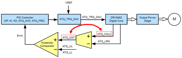
否、方框图是正确的。 PID 回路工作以将 atq_CNT 保持在 atq_LL 和 atq_UL 范围内。 当由于电机负载增加(高于已编程的 atq_UL)而导致 atq_CNT 过高时、PID 回路会增大电机电流(满量程电流)以避免电机丢失步进、这会导致 atq_CNT 更低。 该芯片根据电机 BEMF 与步进输入生成 atq_CNT。
Brian
您好、Brian -San
感谢您的确认。
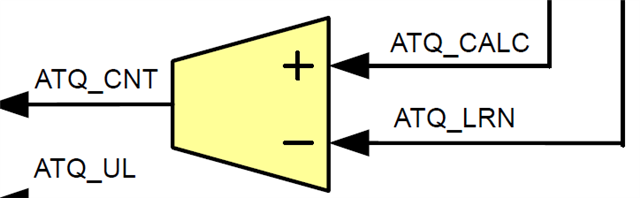
我的理解是、在下面的方框图中、atq_CNT 的值为 tq_Calc 添加到 atq_LRN 中。
如果我有误解、下面的方框图是否意味着 atq_CNT 值是根据 atq_LRN 和 atq_Calc 之间的差异计算得出的?
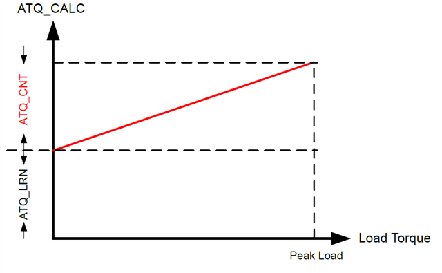
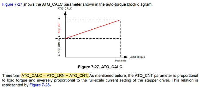
数据表提供了以下图形和公式。 我认为上面的方框图和下面的方程式不匹配。 我对如何理解它感到困惑。
您好!
该块与方程和图之间没有冲突。
atq_Calc = atq_LRN + atq_CNT;以此类推
atq_CNT = atq_Calc - atq_LRN;如方框图所示。
是的、它是 Calc - LRN。
我同意 Brian 提到的内容-方框图没有任何问题。 atq_CNT 为 atq_Calc 减去 atq_LRN。
Dipankar
您好、Brian San Dipankar-San
感谢你的建议。
我很理解。
谢谢。