This thread has been locked.

If you have a related question, please click the "Ask a related question" button in the top right corner. The newly created question will be automatically linked to this question.

[FAQ] [参考译文] [常见问题解答] SK-TDA4VM:如何启用和调试 IMX390 +融合板不能与边缘 AI SDK 配合使用

Guru**** 649970 points
Other Parts Discussed in Thread: SK-TDA4VM
请注意,本文内容源自机器翻译,可能存在语法或其它翻译错误,仅供参考。如需获取准确内容,请参阅链接中的英语原文或自行翻译。

https://e2e.ti.com/support/processors-group/processors/f/processors-forum/1131299/faq-sk-tda4vm-how-do-i-enable-and-debug-imx390-fusion-board-not-working-with-edge-ai-sdk

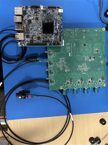
器件型号:SK-TDA4VM

我已将 SK-TDA4VM 电路板与融合板和 IMX390相连。 我将按照有关启用摄像头的 SDK 文档进行操作: https://software-dl.ti.com/jacinto7/esd/processor-sdk-linux-sk-tda4vm/08_02_00/exports/docs/getting_started.html#imx390-raw-sensor

但是、我无法从 IMX390获取摄像头流。 我可以检查什么?

  • 请注意,本文内容源自机器翻译,可能存在语法或其它翻译错误,仅供参考。如需获取准确内容,请参阅链接中的英语原文或自行翻译。

    以下是调试 SK-TDA4VM+FUSION board+IMX390摄像头启用的建议流程。

    与 J721E EVM 不同、SK 电路板没有用于为融合板供电的连接器。 可使用 SK 电路板上的以下器件从外部为融合板加电。 它们插入到与 J721E EVM 相同的电源中(不是用于 SK 的 USB-C)。

    用于融合板的电源连接器:

    适用于 J721E EVM 的电源(EVM 用户指南中推荐使用: https://www.ti.com/lit/ug/spruis4d/spruis4d.pdf?ts=1662476448612): 

    • SDI65-12-U-P6-ND

    用于融合板的电源连接器:

    连接到融合板(图中还连接了1个 IMX390摄像头):

    使用 SK 电路板下侧的40引脚 Samtec 连接器连接至 SK 电路板:

    1.通过查看 dmesg | grep ds90的引导日志,检查融合板是否被电路板检测到。

    • 应将融合板检测为 ds90ub960、日志应显示类似 ds90ub960 8-0036的内容:成功探测(rev/mask 40)(如果成功)。
    • 如果未打印任何内容、请查看 SDK 文档、并确保 uenv.txt 已更新融合板的器件树覆盖。
    • 如果打印以下内容、并且8-0036和8-003d 也相同、则熔接板未通电源或未连接。

    root@tda4vm-sk:/opt/edge_ai_apps# dmesg | grep ds90
    [ 7.440259] ds90ub960 8-0036: ub960_write: cannot write register 0x01 (-121)!
    [ 7.454994] ds90ub960 8-0036: ub960_read: cannot read register 0x01 (-121)!
    [ 7.462114] ds90ub960 8-0036: ub960_read: cannot read register 0x03 (-121)!
    [ 7.471952] ds90ub960 8-0036: Cannot read first register (-121), abort
    [ 7.505439] ds90ub960: probe of 8-0036 failed with error -121
    [ 7.521081] ds90ub960 8-003d: ub960_write: cannot write register 0x01 (-121)!
    [ 7.586269] ds90ub960 8-003d: ub960_read: cannot read register 0x01 (-121)!
    [ 7.593461] ds90ub960 8-003d: ub960_read: cannot read register 0x03 (-121)!
    [ 7.600768] ds90ub960 8-003d: Cannot read first register (-121), abort
    [ 7.614264] ds90ub960: probe of 8-003d failed with error

    • If an error like the following shows up, trying switching the order of the dtbo files such that fusion board comes before camera's dtbo file:

    ERROR: Did not find a cmdline Flattened Device Tree
    Could not find a valid device tree

    2.如果为8-0036和8-003d 打印了不同的值、请使用 i2cdetect -y -r 0x8检查 I2C 地址

    0 1 2 3 4 5 6 7 8 9 a b c d e f
    00: -- -- -- -- -- -- -- -- -- -- -- -- --
    10: -- -- -- -- -- -- -- -- -- -- -- -- -- -- -- --
    20: -- -- -- -- -- -- -- -- -- -- -- -- -- -- -- --
    30: -- -- -- -- -- -- 36 -- -- -- -- -- -- 3d -- --
    40: -- -- -- -- -- -- -- -- -- -- -- -- -- -- -- --
    50: 50 -- -- -- -- -- -- -- -- -- -- -- -- -- -- --
    60: -- -- -- -- -- -- -- -- -- -- -- -- -- -- -- --
    70: UU -- -- -- -- -- -- --

    • 如果显示的地址如下所示、请拔下 SK 电路板和融合板、以便所有器件都完全断电。 首先插入熔融板的电源、然后插入 SK 板的电源。 可能会显示不同的地址、因为熔接板的 I2C 地址由电压电平决定。

    0 1 2 3 4 5 6 7 8 9 a b c d e f
    00: -- -- -- -- -- -- -- -- -- -- -- -- --
    10: -- -- -- -- -- -- -- -- -- -- -- -- -- -- -- --
    20: -- -- -- -- -- -- -- -- -- -- -- -- -- -- -- --
    30: -- -- 32 -- -- -- -- -- -- -- 3a -- -- -- -- --
    40: -- -- -- -- -- -- -- -- -- -- -- -- -- -- -- --
    50: 50 -- -- -- -- -- -- -- -- -- -- -- -- -- -- --
    60: -- -- -- -- -- -- -- -- -- -- -- -- -- -- -- --
    70: UU -- -- -- -- -- -- --

    3. If fusion board is detected, but cameras are not detected properly, a message similar to below will print out:

    Unable to setup formats: Invalid argument (22)
    CSI Camera 0 detected
        device = /dev/video2
        name = ds90ub960 8-003d
        format =  
        subdev_id = 2
        isp_required = 

    • 请确保在 uenv.txt 中使用了正确的摄像机 dtbo 文件。 需要检查的是 RCM 与 CM 以及融合板上摄像头的位置。

    4.正确检测到融合板和摄像机后、将打印一条消息、指出检测到摄像机。 预期输出为:

    [21.521662] init_script.sh[1164]:检测到 IMX390摄像头0
    [21.540467] init_script.sh[1164]:设备=/dev/video20
    [21.540641] init_script.sh[1164]:名称= imx390 10-001A
    [21.540726] init_script.sh[1164]:格式=[fmt:SRGGB12_1x12/1936x1100字段:无]
    [21.540801] init_script.sh[1164]:subdev_id =/dev/v4L-subdev7
    [21.540868] init_script.sh[1164]:ISP_required = yes
    [21.540930] init_script.sh[1164]:LDC_required = yes

    5.要测试摄像机,请使用打印的设备和 subdev_id 编辑 imx390_cam_example.yAML 配置文件,并使用配置文件运行我们的开箱即用演示 app_edgeei。 或者、如果设置并检测到摄像头、使用 v4l2-ctl 并指定输入分辨率和格式应输出 fps:v4l2-ctl -d2 --set-fmt-video =width=1936、height=1100、像素格式=RG12 --stream-mmap