大家好,最近在做TMS320F28335的程序远程升级功能,具体思路如下:
将程序分为:BOOT引导程序和用户程序两个部分;
1、BOOT引导程序定位于FLASH A/B;
2、用户程序定位于FLASH C/D/E/F/G/H;
3、DSP上电后首先进入BOOT程序进行升级判断,若有升级需求,则升级程序,程序升级成功后跳转到用户程序;
4、若无程序升级需求,直接跳转到用户程序;
5、当程序在用户程序中时,接收到程序升级指令后复位,进入BOOT程序,重复步骤3;
现在遇到的问题如下:
在BOOT引导程序执行JumpToApp();(asm(" LB 0x300000"))跳转到用户程序的时候,程序一直在BOOT程序运行,进过测试,初始化程序一直重复执行,
感觉程序好像一直在复位,此时程序并没有正常跳转到用户程序,请问这个是什么原因,本人不吝赐教,谢谢!
BOOT中的cmd文件如下:
MEMORY
{
PAGE 0:
/* Program Memory */
/* Memory (RAM/FLASH/OTP) blocks can be moved to PAGE1 for data allocation */
ZONE0 : origin = 0x004000, length = 0x001000 /* XINTF zone 0 */
/*RAML0 : origin = 0x008000, length = 0x001000*/ /* on-chip RAM block L0 */
PROGRAM : origin = 0x008000, length = 0x001000
RAML1 : origin = 0x009000, length = 0x001000 /* on-chip RAM block L1 */
RAML2 : origin = 0x00A000, length = 0x001000 /* on-chip RAM block L2 */
RAML3 : origin = 0x00B000, length = 0x001000 /* on-chip RAM block L3 */
ZONE6 : origin = 0x0100000, length = 0x100000 /* XINTF zone 6 */
ZONE7A : origin = 0x0200000, length = 0x00FC00 /* XINTF zone 7 - program space */
/*FLASHH : origin = 0x300000, length = 0x008000*/ /* on-chip FLASH */
/*FLASHG : origin = 0x308000, length = 0x008000*/ /* on-chip FLASH */
/*FLASHF : origin = 0x310000, length = 0x008000*/ /* on-chip FLASH */
/*FLASHE : origin = 0x318000, length = 0x008000*/ /* on-chip FLASH */
/*FLASHD : origin = 0x320000, length = 0x008000*/ /* on-chip FLASH */
/*FLASHC : origin = 0x328000, length = 0x008000*/ /* on-chip FLASH */
/*FLASHB : origin = 0x330000, length = 0x008000*/ /* on-chip FLASH */
/*FLASHA : origin = 0x338000, length = 0x007F80*/ /* on-chip FLASH */
PROGAPP : origin = 0x300010, length = 0x02FFF0
BOOTLOADER : origin = 0x330000, length = 0x00FF80
/* Part of FLASHA. Program with all 0x0000 when CSM is in use. */
CSM_RSVD : origin = 0x33FF80, length = 0x000076
/* Part of FLASHA. Used for "boot to Flash" bootloader mode. */
BEGIN : origin = 0x33FFF6, length = 0x000002
/* Part of FLASHA. CSM password locations in FLASHA */
CSM_PWL : origin = 0x33FFF8, length = 0x000008
/* on-chip OTP */
OTP : origin = 0x380400, length = 0x000400
/* ADC_cal function in Reserved memory */
ADC_CAL : origin = 0x380080, length = 0x000009
/* IQ Math Tables in Boot ROM */
IQTABLES : origin = 0x3FE000, length = 0x000b50
/* IQ Math Tables in Boot ROM */
IQTABLES2 : origin = 0x3FEB50, length = 0x00008c
/* FPU Tables in Boot ROM */
FPUTABLES : origin = 0x3FEBDC, length = 0x0006A0
/* Boot ROM */
ROM : origin = 0x3FF27C, length = 0x000D44
/* part of boot ROM */
RESET : origin = 0x3FFFC0, length = 0x000002
/* part of boot ROM */
VECTORS : origin = 0x3FFFC2, length = 0x00003E
PAGE 1 :
/* Data Memory */
/* Memory (RAM/FLASH/OTP) blocks can be moved to PAGE0 for program allocation */
/* Registers remain on PAGE1 */
/* Part of M0, BOOT rom will use this for stack */
BOOT_RSVD : origin = 0x000000, length = 0x000050
/* on-chip RAM block M0 */
RAMM0 : origin = 0x000050, length = 0x0003B0
/* on-chip RAM block M1 */
RAMM1 : origin = 0x000400, length = 0x000400
/* on-chip RAM block L1 */
RAML4 : origin = 0x00C000, length = 0x001000
/* on-chip RAM block L1 */
RAML5 : origin = 0x00D000, length = 0x001000
/* on-chip RAM block L1 */
RAML6 : origin = 0x00E000, length = 0x001000
/* on-chip RAM block L1 */
RAML7 : origin = 0x00F000, length = 0x001000
/* XINTF zone 7 - data space */
ZONE7B : origin = 0x20FC00, length = 0x000400
/*FLASHB : origin = 0x330000, length = 0x008000*/ /* on-chip FLASH */
}
/* Allocate sections to memory blocks.
Note:
codestart user defined section in DSP28_CodeStartBranch.asm used to redirect code
execution when booting to flash
ramfuncs user defined section to store functions that will be copied from Flash into RAM
*/
SECTIONS
{
/* Allocate program areas: */
/*
.cinit : > FLASHA PAGE = 0
.pinit : > FLASHA, PAGE = 0
.text : > FLASHA PAGE = 0
*/
.cinit : > BOOTLOADER PAGE = 0
.pinit : > BOOTLOADER, PAGE = 0
.text : > BOOTLOADER PAGE = 0
codestart : > BEGIN PAGE = 0
Flash28_API:
{
-lFlash28335_API_V210.lib(.econst)
-lFlash28335_API_V210.lib(.text)
}
LOAD = BOOTLOADER,
RUN = PROGRAM,
LOAD_START(_Flash28_API_LoadStart),
LOAD_END(_Flash28_API_LoadEnd),
RUN_START(_Flash28_API_RunStart),
PAGE = 0
ramfuncs : LOAD = BOOTLOADER,
RUN = PROGRAM,
LOAD_START(_RamfuncsLoadStart),
LOAD_END(_RamfuncsLoadEnd),
RUN_START(_RamfuncsRunStart),
LOAD_SIZE(_RamfuncsLoadSize),
PAGE = 0
csmpasswds : > CSM_PWL PAGE = 0
csm_rsvd : > CSM_RSVD PAGE = 0
/* Allocate uninitalized data sections: */
.stack : > RAMM1 PAGE = 1
.ebss : > RAML4 PAGE = 1
.esysmem : > RAMM1 PAGE = 1
/* Initalized sections go in Flash */
/* For SDFlash to program these, they must be allocated to page 0 */
.econst : > BOOTLOADER PAGE = 0
.switch : > BOOTLOADER PAGE = 0
/* Allocate IQ math areas: */
IQmath : > BOOTLOADER PAGE = 0 /* Math Code */
IQmathTables : > IQTABLES, PAGE = 0, TYPE = NOLOAD
/* Uncomment the section below if calling the IQNexp() or IQexp()
functions from the IQMath.lib library in order to utilize the
relevant IQ Math table in Boot ROM (This saves space and Boot ROM
is 1 wait-state). If this section is not uncommented, IQmathTables2
will be loaded into other memory (SARAM, Flash, etc.) and will take
up space, but 0 wait-state is possible.
*/
/*
IQmathTables2 : > IQTABLES2, PAGE = 0, TYPE = NOLOAD
{
IQmath.lib<IQNexpTable.obj> (IQmathTablesRam)
}
*/
FPUmathTables : > FPUTABLES, PAGE = 0, TYPE = NOLOAD
/* Allocate DMA-accessible RAM sections: */
DMARAML4 : > RAML4, PAGE = 1
DMARAML5 : > RAML5, PAGE = 1
DMARAML6 : > RAML6, PAGE = 1
DMARAML7 : > RAML7, PAGE = 1
/* Allocate 0x400 of XINTF Zone 7 to storing data */
ZONE7DATA : > ZONE7B, PAGE = 1
/* .reset is a standard section used by the compiler. It contains the */
/* the address of the start of _c_int00 for C Code. /*
/* When using the boot ROM this section and the CPU vector */
/* table is not needed. Thus the default type is set here to */
/* DSECT */
.reset : > RESET, PAGE = 0, TYPE = DSECT
vectors : > VECTORS PAGE = 0, TYPE = DSECT
/* Allocate ADC_cal function (pre-programmed by factory into TI reserved memory) */
.adc_cal : load = ADC_CAL, PAGE = 0, TYPE = NOLOAD
}
用户程序中的CMD文件如下:
MEMORY
{
PAGE 0:
/* Program Memory */
/* Memory (RAM/FLASH/OTP) blocks can be moved to PAGE1 for data allocation */
ZONE0 : origin = 0x004000, length = 0x001000 /* XINTF zone 0 */
/*RAML0 : origin = 0x008000, length = 0x001000*/ /* on-chip RAM block L0 */
PROGRAM : origin = 0x008000, length = 0x001000
RAML1 : origin = 0x009000, length = 0x001000 /* on-chip RAM block L1 */
RAML2 : origin = 0x00A000, length = 0x001000 /* on-chip RAM block L2 */
RAML3 : origin = 0x00B000, length = 0x001000 /* on-chip RAM block L3 */
ZONE6 : origin = 0x0100000, length = 0x100000 /* XINTF zone 6 */
ZONE7A : origin = 0x0200000, length = 0x00FC00 /* XINTF zone 7 - program space */
/*FLASHH : origin = 0x300000, length = 0x008000*/ /* on-chip FLASH */
/*FLASHG : origin = 0x308000, length = 0x008000*/ /* on-chip FLASH */
/*FLASHF : origin = 0x310000, length = 0x008000*/ /* on-chip FLASH */
/*FLASHE : origin = 0x318000, length = 0x008000*/ /* on-chip FLASH */
/*FLASHD : origin = 0x320000, length = 0x008000*/ /* on-chip FLASH */
/*FLASHC : origin = 0x328000, length = 0x008000*/ /* on-chip FLASH */
/*FLASHB : origin = 0x330000, length = 0x008000*/ /* on-chip FLASH */
/*FLASHA : origin = 0x338000, length = 0x007F80*/ /* on-chip FLASH */
PROGAPP : origin = 0x300010, length = 0x02FFF0
BOOTLOADER : origin = 0x330000, length = 0x00FF80
/* Part of FLASHA. Program with all 0x0000 when CSM is in use. */
CSM_RSVD : origin = 0x33FF80, length = 0x000076
/* Part of FLASHA. Used for "boot to Flash" bootloader mode. */
BEGIN : origin = 0x33FFF6, length = 0x000002/**/
/* Part of FLASHA. Used for "boot to Flash" bootloader mode. */
/*BEGIN : origin = 0x300000, length = 0x000010*/
/* Part of FLASHA. CSM password locations in FLASHA */
CSM_PWL : origin = 0x33FFF8, length = 0x000008
/* on-chip OTP */
OTP : origin = 0x380400, length = 0x000400
/* ADC_cal function in Reserved memory */
ADC_CAL : origin = 0x380080, length = 0x000009
/* IQ Math Tables in Boot ROM */
IQTABLES : origin = 0x3FE000, length = 0x000b50
/* IQ Math Tables in Boot ROM */
IQTABLES2 : origin = 0x3FEB50, length = 0x00008c
/* FPU Tables in Boot ROM */
FPUTABLES : origin = 0x3FEBDC, length = 0x0006A0
/* Boot ROM */
ROM : origin = 0x3FF27C, length = 0x000D44
/* part of boot ROM */
RESET : origin = 0x3FFFC0, length = 0x000002
/* part of boot ROM */
VECTORS : origin = 0x3FFFC2, length = 0x00003E
PAGE 1 :
/* Data Memory */
/* Memory (RAM/FLASH/OTP) blocks can be moved to PAGE0 for program allocation */
/* Registers remain on PAGE1 */
/* Part of M0, BOOT rom will use this for stack */
BOOT_RSVD : origin = 0x000000, length = 0x000050
/* on-chip RAM block M0 */
RAMM0 : origin = 0x000050, length = 0x0003B0
/* on-chip RAM block M1 */
RAMM1 : origin = 0x000400, length = 0x000400
/* on-chip RAM block L1 */
RAML4 : origin = 0x00C000, length = 0x001000
/* on-chip RAM block L1 */
RAML5 : origin = 0x00D000, length = 0x001000
/* on-chip RAM block L1 */
RAML6 : origin = 0x00E000, length = 0x001000
/* on-chip RAM block L1 */
RAML7 : origin = 0x00F000, length = 0x001000
/* XINTF zone 7 - data space */
ZONE7B : origin = 0x20FC00, length = 0x000400
/*FLASHB : origin = 0x330000, length = 0x008000*/ /* on-chip FLASH */
}
/* Allocate sections to memory blocks.
Note:
codestart user defined section in DSP28_CodeStartBranch.asm used to redirect code
execution when booting to flash
ramfuncs user defined section to store functions that will be copied from Flash into RAM
*/
SECTIONS
{
/* Allocate program areas: */
/*
.cinit : > FLASHA PAGE = 0
.pinit : > FLASHA, PAGE = 0
.text : > FLASHA PAGE = 0
*/
.cinit : > PROGAPP PAGE = 0
.pinit : > PROGAPP, PAGE = 0
.text : > PROGAPP PAGE = 0
codestart : > BEGIN PAGE = 0
ramfuncs : LOAD = PROGAPP,
RUN = PROGRAM,
LOAD_START(_RamfuncsLoadStart),
LOAD_END(_RamfuncsLoadEnd),
RUN_START(_RamfuncsRunStart),
LOAD_SIZE(_RamfuncsLoadSize),
PAGE = 0
csmpasswds : > CSM_PWL PAGE = 0
csm_rsvd : > CSM_RSVD PAGE = 0
/* Allocate uninitalized data sections: */
.stack : > RAMM1 PAGE = 1
.ebss : > RAML4 PAGE = 1
.esysmem : > RAMM1 PAGE = 1
/* Initalized sections go in Flash */
/* For SDFlash to program these, they must be allocated to page 0 */
.econst : > PROGAPP PAGE = 0
.switch : > PROGAPP PAGE = 0
/* Allocate IQ math areas: */
IQmath : > PROGAPP PAGE = 0 /* Math Code */
IQmathTables : > IQTABLES, PAGE = 0, TYPE = NOLOAD
/* Uncomment the section below if calling the IQNexp() or IQexp()
functions from the IQMath.lib library in order to utilize the
relevant IQ Math table in Boot ROM (This saves space and Boot ROM
is 1 wait-state). If this section is not uncommented, IQmathTables2
will be loaded into other memory (SARAM, Flash, etc.) and will take
up space, but 0 wait-state is possible.
*/
/*
IQmathTables2 : > IQTABLES2, PAGE = 0, TYPE = NOLOAD
{
IQmath.lib<IQNexpTable.obj> (IQmathTablesRam)
}
*/
FPUmathTables : > FPUTABLES, PAGE = 0, TYPE = NOLOAD
/* Allocate DMA-accessible RAM sections: */
DMARAML4 : > RAML4, PAGE = 1
DMARAML5 : > RAML5, PAGE = 1
DMARAML6 : > RAML6, PAGE = 1
DMARAML7 : > RAML7, PAGE = 1
/* Allocate 0x400 of XINTF Zone 7 to storing data */
ZONE7DATA : > ZONE7B, PAGE = 1
/* .reset is a standard section used by the compiler. It contains the */
/* the address of the start of _c_int00 for C Code. /*
/* When using the boot ROM this section and the CPU vector */
/* table is not needed. Thus the default type is set here to */
/* DSECT */
.reset : > RESET, PAGE = 0, TYPE = DSECT
vectors : > VECTORS PAGE = 0, TYPE = DSECT
/* Allocate ADC_cal function (pre-programmed by factory into TI reserved memory) */
.adc_cal : load = ADC_CAL, PAGE = 0, TYPE = NOLOAD
}
进一步排查原因后发现,自己修改的CMD没有什么问题,原因是由于硬件连接问题,这里给出硬件连接图:
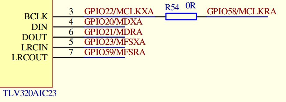
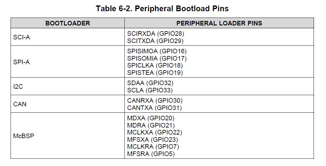
在硬件中只要将GPIO20~GPIO23、GPIO59(这五个DSP引脚是直接接到TLV320AI23芯片上的)与TLV320AIC23相连的电气关系断开之后,BOOTLOADR程序就可以正常跳转到用户APP程序,具体是GPIO20~GPIO23、GPIO59引脚中的那个引脚就没有在做进一步考究。
这里就有点疑惑,想请教一下,知道这几个引脚对DSP内部跳转程序指令有什么影响吗?或者说这几个DSP引脚需要什么样的电平才可以正常跳转程序?