

Other Parts Discussed in Thread: LAUNCHXL-F280025C, BOOSTXL-DRV8323RS
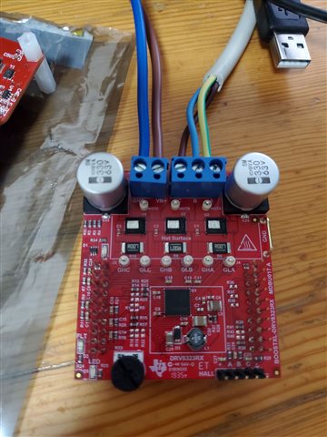
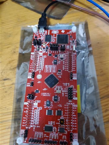
 F280025C +8323RS
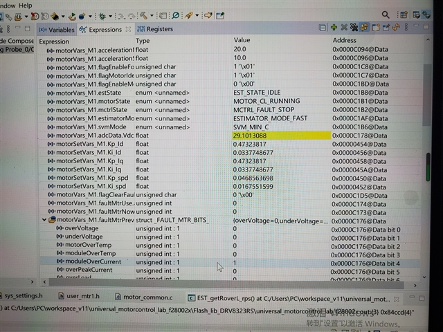
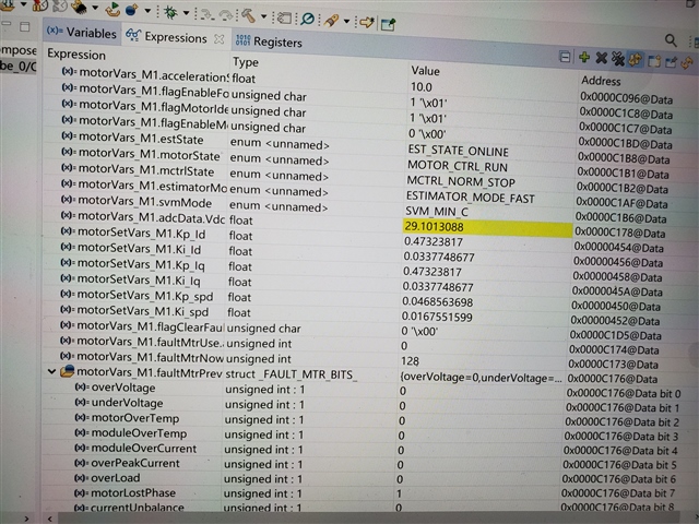
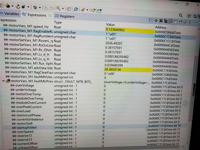
DMC_BUILDLEVEL设置为DMC_LEVEL_4来构建和加载项目 当接上电机时 出现了moduleOverCurrent = 1 和 flagEnableRunAndIdentify =0 的情况
拆除电机后 则不会出现moduleOverCurrent = 1 的情况 这个该怎么解决呢
Original question:

F280025C +8323RS
DMC_BUILDLEVEL设置为DMC_LEVEL_4来构建和加载项目 当接上电机时 出现了moduleOverCurrent = 1 和 flagEnableRunAndIdentify =0 的情况
拆除电机后 则不会出现moduleOverCurrent = 1 的情况 这个该怎么解决呢


 是按照文档要求来的
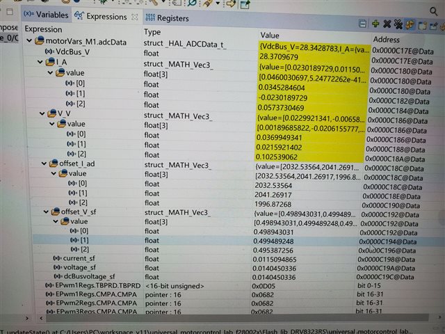
 这是8323RS+F28027F LAB5运行 也是能运行的
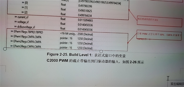 这是文档的
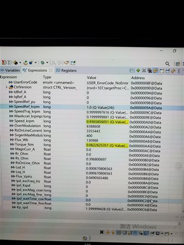
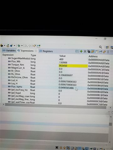
这是文档的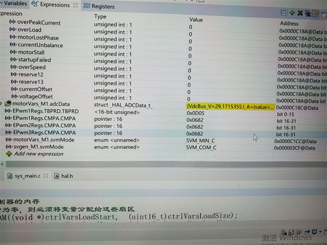 这是我电脑测试的 和文档不一样