This thread has been locked.

If you have a related question, please click the "Ask a related question" button in the top right corner. The newly created question will be automatically linked to this question.

MSP430FR2433: 捕获定时器时钟配置确认

Part Number: MSP430FR2433
Other Parts Discussed in Thread: MSP-EXP430FR2433

你好

     我们使用的MSP-EXP430FR2433开发模块,目前关于CS及capture timerA进行了如下配置:

CS 配置:(配置MCLK为16Mhz时钟) 

#define CS_MCLK_DESIRED_FREQUENCY_IN_KHZ 16000//16Mhz
#define CS_MCLK_FLLREF_RATIO 489//16Mhz/32768hz

    //Set DCO FLL reference = REFO
    CS_initClockSignal(
        CS_FLLREF,
        CS_REFOCLK_SELECT,
        CS_CLOCK_DIVIDER_1
    );
    
    //Set ACLK = REFO
    CS_initClockSignal(
        CS_ACLK,
        CS_REFOCLK_SELECT,
        CS_CLOCK_DIVIDER_1
    );
    
    //Create struct variable to store proper software trim values
    CS_initFLLParam param = {0};
    
    //Set Ratio/Desired MCLK Frequency, initialize DCO, save trim values
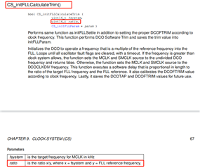
    CS_initFLLCalculateTrim(
        CS_MCLK_DESIRED_FREQUENCY_IN_KHZ,
        CS_MCLK_FLLREF_RATIO,
        &param
    );
    
    //Clear all OSC fault flag
    CS_clearAllOscFlagsWithTimeout(1000);

    //For demonstration purpose, change DCO clock freq to 16MHz
    CS_initFLLSettle(
        16000,
        487
    );

    //Clear all OSC fault flag
    CS_clearAllOscFlagsWithTimeout(1000);
    
    //Reload DCO trim values that were calculated earlier
    CS_initFLLLoadTrim(
        CS_MCLK_DESIRED_FREQUENCY_IN_KHZ,
        CS_MCLK_FLLREF_RATIO,
        &param
    );
    
    //Clear all OSC fault flag
    CS_clearAllOscFlagsWithTimeout(1000);
    
    //Enable oscillator fault interrupt
    SFR_enableInterrupt(SFR_OSCILLATOR_FAULT_INTERRUPT);

capture配置(P1.1捕获引脚):

    //capture
    P1SEL1 |= BIT1;                                 // TA0.CCI1A input capture pin, second function
    P1REN |= BIT1;                                  // enable internal pull-down resistor
    P1OUT |= BIT1;
    
    TA0CCTL1 |= CM_3 | CCIS_0 | CCIE | CAP | SCS;
    TA0CTL |= TASSEL_2 | MC_2 | TACLR | TAIE;
    
/* 捕获触发中断 */
#if defined(__TI_COMPILER_VERSION__) || defined(__IAR_SYSTEMS_ICC__)
#pragma vector = TIMER0_A1_VECTOR
__interrupt void TIMER0_A1_ISR(void)
#elif defined(__GNUC__)
void __attribute__ ((interrupt(TIMER0_A1_VECTOR))) TIMER0_A1_ISR (void)
#else
#error Compiler not supported!
#endif
{
    switch(__even_in_range(TA0IV,TA0IV_TAIFG))
    {
        case TA0IV_NONE:
            break;                                  // No interrupt
        case TA0IV_TACCR1:
            if (GPIO_INPUT_PIN_LOW == GPIO_getInputPinValue(GPIO_PORT_P1, GPIO_PIN1))
            {
                overflowCounter = 0;                //Reset number of overflows
                startTime = 0;                      //Reset timer variable and CCR2, start timer in cont mode
                TA0CCR1 = 0;
                TA0CTL |= TACLR | MC_2;
            }
            else
            {
                endTime = TA0CCR1;              //Stop timer
                TA0CTL |= MC_0;

                //elapsedTime(单位 ms)       4.096ms = ((1/16Mhz)*0xFFFF * 10^3)
                elapsedTime = (float)(4.096*(float)(overflowCounter)) + (float)((float)(endTime) / 16000);

            }
            edgeFlag ^= 1;

            break;                                  // CCR1 not used
        case TA0IV_TACCR2:
            break;                                  // CCR2 not used
        case TA0IV_TAIFG:
            overflowCounter++;
            break;                                  // overflow
        default:
            break;
    }
}

目前有两个问题想确认一下:

1.CS的配置接口调用是否正常,同时16Mhz情况下关于ratio参数的计算方法是否正常,16Mhz/32678hz ≈489

2.capture 中断内TA0IV_TAIFG的elapsedTime计算方法是否正确?以ms为单位计算

//elapsedTime(单位 ms)       4.096ms = ((1/16Mhz)*0xFFFF * 10^3)

elapsedTime = (float)(4.096*(float)(overflowCounter)) + (float)((float)(endTime) / 16000);

  • 1.CS的配置接口调用是否正常,同时16Mhz情况下关于ratio参数的计算方法是否正常,16Mhz/32678hz ≈489

    看起来没什么问题。我们有个寄存器版本的例程,您也可以参考

    /* --COPYRIGHT--,BSD_EX
     * Copyright (c) 2014, Texas Instruments Incorporated
     * All rights reserved.
     *
     * Redistribution and use in source and binary forms, with or without
     * modification, are permitted provided that the following conditions
     * are met:
     *
     * *  Redistributions of source code must retain the above copyright
     *    notice, this list of conditions and the following disclaimer.
     *
     * *  Redistributions in binary form must reproduce the above copyright
     *    notice, this list of conditions and the following disclaimer in the
     *    documentation and/or other materials provided with the distribution.
     *
     * *  Neither the name of Texas Instruments Incorporated nor the names of
     *    its contributors may be used to endorse or promote products derived
     *    from this software without specific prior written permission.
     *
     * THIS SOFTWARE IS PROVIDED BY THE COPYRIGHT HOLDERS AND CONTRIBUTORS "AS IS"
     * AND ANY EXPRESS OR IMPLIED WARRANTIES, INCLUDING, BUT NOT LIMITED TO,
     * THE IMPLIED WARRANTIES OF MERCHANTABILITY AND FITNESS FOR A PARTICULAR
     * PURPOSE ARE DISCLAIMED. IN NO EVENT SHALL THE COPYRIGHT OWNER OR
     * CONTRIBUTORS BE LIABLE FOR ANY DIRECT, INDIRECT, INCIDENTAL, SPECIAL,
     * EXEMPLARY, OR CONSEQUENTIAL DAMAGES (INCLUDING, BUT NOT LIMITED TO,
     * PROCUREMENT OF SUBSTITUTE GOODS OR SERVICES; LOSS OF USE, DATA, OR PROFITS;
     * OR BUSINESS INTERRUPTION) HOWEVER CAUSED AND ON ANY THEORY OF LIABILITY,
     * WHETHER IN CONTRACT, STRICT LIABILITY, OR TORT (INCLUDING NEGLIGENCE OR
     * OTHERWISE) ARISING IN ANY WAY OUT OF THE USE OF THIS SOFTWARE,
     * EVEN IF ADVISED OF THE POSSIBILITY OF SUCH DAMAGE.
     *
     *******************************************************************************
     *
     *                       MSP430 CODE EXAMPLE DISCLAIMER
     *
     * MSP430 code examples are self-contained low-level programs that typically
     * demonstrate a single peripheral function or device feature in a highly
     * concise manner. For this the code may rely on the device's power-on default
     * register values and settings such as the clock configuration and care must
     * be taken when combining code from several examples to avoid potential side
     * effects. Also see www.ti.com/grace for a GUI- and www.ti.com/msp430ware
     * for an API functional library-approach to peripheral configuration.
     *
     * --/COPYRIGHT--*/
    //***************************************************************************************
    //  MSP430FR24xx Demo - Timer0_A3 Capture of ACLK
    //
    //  Description: Capture a number of periods of the ACLK clock and store them in an array.
    //  When the set number of periods is captured the program is trapped and the LED on
    //  P1.0 is toggled. At this point halt the program execution read out the values using
    //  the debugger.
    //  ACLK = REFOCLK = 32kHz, MCLK = SMCLK = default DCODIV = 1MHz.
    //
    //                MSP430FR2433
    //             -----------------
    //         /|\|                 |
    //          | |             P1.2|<-- TA0.CCI2A
    //          --|RST              |  |
    //            |             P2.2|--> ACLK
    //            |                 |
    //            |             P1.0|-->LED
    //
    //
    //  Wei Zhao
    //  Texas Instruments Inc.
    //  Jan 2014
    //  Built with IAR Embedded Workbench v6.20 & Code Composer Studio v6.0.1
    //***************************************************************************************
    #include <msp430.h>
    
    #define NUMBER_TIMER_CAPTURES        20
    
    volatile unsigned int timerAcaptureValues[NUMBER_TIMER_CAPTURES];
    unsigned int timerAcapturePointer = 0;
    
    int main(void)
    {
        WDTCTL = WDTPW | WDTHOLD;                       // Stop watchdog timer
    
        // Configure GPIO
        P1DIR |= BIT0;                                  // Set P1.0 as output
        P1OUT |= BIT0;                                  // P1.0 high
        P1SEL1 |= BIT2;                                 // TA0.CCI2A input capture pin, second function
        P1REN |= BIT2;                                  // enable internal pull-down resistor
        P1OUT &= ~BIT2;
    
        P2SEL1 |= BIT2;                                 // Set as ACLK pin, second function
        P2DIR |= BIT2;
    
        // Disable the GPIO power-on default high-impedance mode to activate
        // previously configured port settings
        PM5CTL0 &= ~LOCKLPM5;
    
        // Configure clock
        __bis_SR_register(SCG0);                        // disable FLL
        CSCTL3 |= SELREF__REFOCLK;                      // Set REFO as FLL reference source
        CSCTL0 = 0;                                     // clear DCO and MOD registers
        CSCTL1 &= ~(DCORSEL_7);                         // Clear DCO frequency select bits first
        CSCTL1 |= DCORSEL_2;                            // Set DCO = 4MHz
        CSCTL2 = FLLD_1 + 60;                           // DCODIV = 2MHz
        __delay_cycles(3);
        __bic_SR_register(SCG0);                        // enable FLL
        while(CSCTL7 & (FLLUNLOCK0 | FLLUNLOCK1));      // Poll until FLL is locked
    
        CSCTL4 = SELMS__DCOCLKDIV | SELA__REFOCLK;      // set default REFO(~32768Hz) as ACLK source, ACLK = 32768Hz
                                                        // default DCODIV as MCLK and SMCLK source
        CSCTL5 |= DIVM__1 | DIVS__2;                    // SMCLK = 1MHz, MCLK = 2MHz
    
        // Timer0_A3 Setup
        TA0CCTL2 |= CM_1 | CCIS_0 | CCIE | CAP | SCS;
                                                        // Capture rising edge,
                                                        // Use CCI2A=ACLK,
                                                        // Synchronous capture,
                                                        // Enable capture mode,
                                                        // Enable capture interrupt
    
        TA0CTL |= TASSEL_2 | MC_2 | TACLR;              // Use SMCLK as clock source, clear TA0R
                                                        // Start timer in continuous mode
    
        __bis_SR_register(LPM0_bits | GIE);
        __no_operation();
    }
    
    // Timer0_A3 CC1-2, TA Interrupt Handler
    #if defined(__TI_COMPILER_VERSION__) || defined(__IAR_SYSTEMS_ICC__)
    #pragma vector = TIMER0_A1_VECTOR
    __interrupt void TIMER0_A1_ISR(void)
    #elif defined(__GNUC__)
    void __attribute__ ((interrupt(TIMER0_A1_VECTOR))) TIMER0_A1_ISR (void)
    #else
    #error Compiler not supported!
    #endif
    {
        switch(__even_in_range(TA0IV,TA0IV_TAIFG))
        {
            case TA0IV_NONE:
                break;                                  // No interrupt
            case TA0IV_TACCR1:
                break;                                  // CCR1 not used
            case TA0IV_TACCR2:
                timerAcaptureValues[timerAcapturePointer++] = TA0CCR2;
                if (timerAcapturePointer >= 20)
                {
                    while (1)
                    {
                        P1OUT ^= 0x01;                  // Toggle P1.0 (LED)
                        __delay_cycles(100000);
                    }
                }
                break;                                  // CCR2 not used
            case TA0IV_TAIFG:
                break;                                  // overflow
            default:
                break;
        }
    }
    

    capture 中断内TA0IV_TAIFG的elapsedTime计算方法是否正确?以ms为单位计算

    能否详细说下您要实现的功能?另外请问您的overflowCounter是哪里定义的?

  • Hi Susan Yang

        我们将P1.1引脚作为捕获引脚,用来捕获pwm波形,根据低电平持续事件来解析对应事件,要精确到us级别。所以我们配置捕获定时器使用SMCLK(TASSEL_2),并将其配置为16Mhz.

        关于overflowCounter 是个全局变量, 用来统计进入溢出信号(TA0IV_TAIFG)的次数,用来统计低电平持续的时间。

    所以才会有下述计算方法:用来统计低电平持续的时间。

    //elapsedTime(单位 ms) 4.096ms = ((1/16Mhz)*0xFFFF * 10^3)
    elapsedTime = (float)(4.096*(float)(overflowCounter)) + (float)((float)(endTime) / 16000);


  • 谢谢您的详细反馈。

    根据低电平持续事件来解析对应事件,要精确到us级别。

    您的应用像是使用定时器的捕获功能来测量脉冲的宽度。

    您可以利用两次捕获的值来测量脉冲的宽度或者通过捕获上升沿与下降沿来判断

    请问您现在需要捕获的脉冲参数是怎样的?目前测试情况如何?

  • 是的,我们确实是要通过捕获定时器测量脉冲宽度,可以理解为低电平的持续时间。

    所以我们目前capture定时器配置的双边沿采样。你可以在中断代码内看到TA0IV_TACCR1事件,我们判断引脚为低(下降沿)时清除计数,反之则为上升沿,此时取elapsedTime参数为低电平持续时间。

    case TA0IV_TACCR1:
    if (GPIO_INPUT_PIN_LOW == GPIO_getInputPinValue(GPIO_PORT_P1, GPIO_PIN1))

    目前需要捕获脉冲为15.6ms/670us/330us 的低电平持续时间。但是目前读取的elapsedTime与示波器概率性数据概率性存在误差。所以想请你们帮助排查一下16Mhz CS配置是否正确?elapsedTime的计算方法是否正确?

  • 所以想请你们帮助排查一下16Mhz CS配置是否正确?elapsedTime的计算方法是否正确?

    根据您的代码,看起来没什么问题

    但是目前读取的elapsedTime与示波器概率性数据概率性存在误差。

    误差大概是怎样?您使用的是开发板?

  • 误差大概是怎样?您使用的是开发板?

    根据目前的配置尝试捕获15.67ms左右波形,我们尝试过滤14ms~17ms范围,但是还是可能出现13ms的情况或者更差。

    尝试用示波器测试,低电平持续时间保持在16ms左右。

    我们是烧录到我们自己的开发板上的FR2433芯片,具体如下。

  • 我们是烧录到我们自己的开发板上的FR2433芯片,具体如下。

    若是可以,请给出或私信一下您的工程,我在开发板上测试一下,以排除硬件上造成的误差

  • 你好,工程已私信发送,请帮助排查一下,我们这边P1.1捕获引脚有外接一个其他PWM输出,如果你要测试。需要给P1.1,模拟一个输入信号用来测试

  • 工程已私信发送

    我已经收到您的工程了,会在确认后回复您

  • 顺带说一句,我将工程内elapsedTime = (4096*overflowCounter) + (endTime/16);改为了int类型,单位为us。

  • 请查收一下私信

  • 你好,关于仪表目前无法使用的情况,请问是否可以协调有测试环境的同事帮助测试一下?谢谢

  • 建议您在英文E2E发帖询问一下

    https://e2e.ti.com/support/microcontrollers/msp-low-power-microcontrollers-group/