This thread has been locked.

If you have a related question, please click the "Ask a related question" button in the top right corner. The newly created question will be automatically linked to this question.

MSP430-I2C 硬件模块的时钟设置问题

Other Parts Discussed in Thread: TMP112, MSP430F5659

您好,我用msp430f5659想要读取tmp112温度传感器的数据,

IIC设置如下,使用ACLK为时钟,ACLK设置为32768的外部晶振

UCB1CTL1 |= UCSWRST; 
UCB1CTL0 = UCMST | UCMODE_3 | UCSYNC; 
UCB1CTL1 = UCSSEL_1 | UCSWRST; 
UCB1BR0 = 1; 
UCB1BR1 = 0;
UCB1I2CSA = TEMPM_TEMPSLAVEADDRESS_W; 
UCB1CTL1 &= ~UCSWRST; // Clear SW reset, resume operation
UCB1IE |= UCTXIE; // Enable TX interrupt

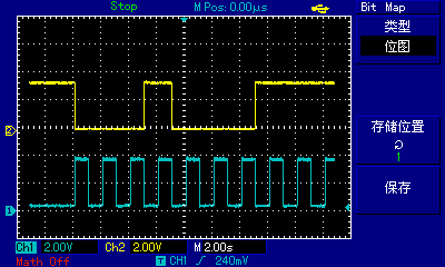
当我用示波器观察IIC的时钟信号时(P8.6),发现时钟频率是1Hz,并不是我预计的32768Hz。

请您帮我看看这个是什么原因。。。

PS:

我把IIC的时钟设为SMCLK(1Mhz),用示波器观察到P8.6的输出为16Hz

  • Hi zheng,

      应该是你对UCB1CTL0和UCB1CTL1两个寄存器赋值的操作有问题,试着按下面的格式改一下试试:

    UCB0CTL0 = UCMST + UCMODE_3 + UCSYNC; // I2C Master, synchronous mode
    UCB0CTL1 = UCSSEL_1 + UCSWRST; 

    谢谢

    ken

  • 谢谢您的答复,我修改为以下设置了,单结果没有变化。

    UCB1CTL0 = UCMST + UCMODE_3 + UCSYNC; // I2C Master, synchronous mode
    UCB1CTL1 = UCSSEL_1 + UCSWRST; 

  • 谢谢您的回复,我修改为以下设置了,单结果没有改变。

    UCB1CTL0 = UCMST + UCMODE_3 + UCSYNC; // I2C Master, synchronous mode
    UCB1CTL1 = UCSSEL_1 + UCSWRST; 

  • Hi Zheng,

      你的系统能正常工作了吗?I2C有没有建立通信呢?同时在硬件上面I2C总线的SCL和SDA两个管脚有没有才去电阻上拉的操作?

    谢谢

    ken

  • Hi zheng,

       另外由于PIN8.5和PIN8.6是多功能复合的管脚,针对他们的功能选择寄存器,你是怎么配置的呢?有没有正确的配置?

    谢谢

    ken

  • 谢谢您回复,我的系统能正常工作,SPI和UART的功能都能正常运行。

    现在只是I2C无法建立通信,因为tmp112需要的时钟至少是1Khz。

    在硬件上面I2C总线的SCL和SDA两个管脚的电压为3.3v,没有问题。

  • 您好,端口是这样设置的

    GPIO_setAsPeripheralModuleFunctionInputPin(GPIO_PORT_P8,GPIO_PIN5 + GPIO_PIN6);

    这个应该也没有问题,我用这个方法设置的SPI和UART都能正常工作。

  • Hi zheng,

      不好意思,问一下。你描述的这个函数是自己定义的吗?以前没有用到类似的函数,想请教一下。

    能看一下这个函数具体的定义吗?

    谢谢

    ken

  • 您好,这个函数用的是TI的Drivelib,定义是:

    void GPIO_setAsPeripheralModuleFunctionInputPin(
    uint8_t selectedPort,
    uint16_t selectedPins
    )
    {
    assert((GPIO_PORT_P1 == selectedPort) || (GPIO_PORT_P2 == selectedPort) ||
    (GPIO_PORT_P3 == selectedPort) || (GPIO_PORT_P4 == selectedPort) ||
    (GPIO_PORT_P5 == selectedPort) || (GPIO_PORT_P6 == selectedPort) ||
    (GPIO_PORT_P7 == selectedPort) || (GPIO_PORT_P8 == selectedPort) ||
    (GPIO_PORT_P9 == selectedPort) || (GPIO_PORT_P10 == selectedPort) ||
    (GPIO_PORT_P11 == selectedPort) || (GPIO_PORT_PA == selectedPort) ||
    (GPIO_PORT_PB == selectedPort) || (GPIO_PORT_PC == selectedPort) ||
    (GPIO_PORT_PD == selectedPort) || (GPIO_PORT_PE == selectedPort) ||
    (GPIO_PORT_PF == selectedPort) || (GPIO_PORT_PJ == selectedPort)
    );

    assert(0x00 != (selectedPins & (GPIO_PIN0 + GPIO_PIN1 + GPIO_PIN2 +
    GPIO_PIN3 + GPIO_PIN4 + GPIO_PIN5 +
    GPIO_PIN6 + GPIO_PIN7 + GPIO_PIN8 +
    GPIO_PIN9 + GPIO_PIN10 + GPIO_PIN11 +
    GPIO_PIN12 + GPIO_PIN13 + GPIO_PIN14 +
    GPIO_PIN15
    )));

    uint32_t baseAddress = privateGPIOGetBaseAddress(selectedPort);

    assert((0xFFFF != baseAddress) );
    if (0xFFFF == baseAddress)
    return;


    switch (selectedPort) {
    case GPIO_PORT_P1:
    case GPIO_PORT_P3:
    case GPIO_PORT_P5:
    case GPIO_PORT_P7:
    case GPIO_PORT_P9:
    HWREG8(baseAddress + OFS_P1SEL) |= (uint8_t)selectedPins;
    HWREG8(baseAddress + OFS_P1DIR) &= (uint8_t) ~selectedPins;
    break;
    case GPIO_PORT_P2:
    case GPIO_PORT_P4:
    case GPIO_PORT_P6:
    case GPIO_PORT_P8:
    case GPIO_PORT_P10:
    HWREG8(baseAddress + OFS_P2SEL) |= (uint8_t)selectedPins;
    HWREG8(baseAddress + OFS_P2DIR) &= (uint8_t) ~selectedPins;
    break;
    case GPIO_PORT_PA:
    case GPIO_PORT_PB:
    case GPIO_PORT_PC:
    case GPIO_PORT_PD:
    case GPIO_PORT_PE:
    case GPIO_PORT_PF:
    case GPIO_PORT_PJ:
    case GPIO_PORT_P11:
    HWREG16(baseAddress + OFS_PASEL) |= selectedPins;
    HWREG16(baseAddress + OFS_PADIR) &= ~selectedPins;
    break;
    }
    }

  • Hi zheng,

      谢谢你的信息,它的作用和设置P6DIR + P8SEL是一样的。(P8SEL = 0x60; P8DIR = 0x60)

    如果都是这样的话,这在软件配置方面,应该是没有问题的啊。因为我们的实例代码就是这样测试的。

    其余的只能是检查I2C的硬件连接了,如果SDA和SCL上面都有上拉电阻的话,整个通信应该是能正常工作。

    谢谢

    ken

  • 谢谢您的回复,我用了TI的例程msp430f665x_uscib0_i2c_07试了试,发现结果没有变化。

    您看看还有什么原因能影响I2C时钟频率呢。

  • Hi zheng,

       现在感觉还真没什么办法测了。要不你试试用芯片上的另外一组IIC的接口来通信看看。试着排除一下芯片功能的问题。

    谢谢

    ken

  • 你好,

    IIC时钟是1HZ是不可能的,你有尝试把ACK做输出看其频率是否是32768HZ吗?

    你是如何测量IIC时钟频率的,写一帧数据然后测量CLK周期?

    可以把你的波形贴出来吗?SDA和SLK的。

  • 您好,谢谢您的回复。

    ACLK输出32768HZ我测量过没有问题,

    我把IIC的波形发给您看看。。

    SDA是CH2,SLC是CH1.

  • 谢谢您的回复。

    ACK输出是32768HZ,我用示波器确认了。

    我把I2C的波形发给您看看。

    CH1是SLK,CH2是SDA。。

  • 你好,

    你截图的是IIC寻地址的波形吗?

    可能是带宽不够的原因,我看你一帧完整波形没有截取下来,我本来打算看一下ACK回复信号和一帧完整的寻地址波形。

    1.出现你这个原因我有点疑惑,在用SMCLK作为IIC时钟源的时候,能不能尝试改变一下波特率设置寄存器的值,我看你给的是1,改UCBxBR0的值。看输出是否还是16HZ。

    2.检查是不是其他硬件模块,SPI,UART和IIC共用了同一个模块?可能性比较小

    3.GPIO设置问题,能否尝试一下,单独写一个测试用例,用drive lib测试IIC模块,其他东西我都不加,用于诊断问题点。

    测试代码如下,或者你在drive lib里面找:

    /* --COPYRIGHT--,BSD
    * Copyright (c) 2012, Texas Instruments Incorporated
    * All rights reserved.
    *
    * Redistribution and use in source and binary forms, with or without
    * modification, are permitted provided that the following conditions
    * are met:
    *
    * * Redistributions of source code must retain the above copyright
    * notice, this list of conditions and the following disclaimer.
    *
    * * Redistributions in binary form must reproduce the above copyright
    * notice, this list of conditions and the following disclaimer in the
    * documentation and/or other materials provided with the distribution.
    *
    * * Neither the name of Texas Instruments Incorporated nor the names of
    * its contributors may be used to endorse or promote products derived
    * from this software without specific prior written permission.
    *
    * THIS SOFTWARE IS PROVIDED BY THE COPYRIGHT HOLDERS AND CONTRIBUTORS "AS IS"
    * AND ANY EXPRESS OR IMPLIED WARRANTIES, INCLUDING, BUT NOT LIMITED TO,
    * THE IMPLIED WARRANTIES OF MERCHANTABILITY AND FITNESS FOR A PARTICULAR
    * PURPOSE ARE DISCLAIMED. IN NO EVENT SHALL THE COPYRIGHT OWNER OR
    * CONTRIBUTORS BE LIABLE FOR ANY DIRECT, INDIRECT, INCIDENTAL, SPECIAL,
    * EXEMPLARY, OR CONSEQUENTIAL DAMAGES (INCLUDING, BUT NOT LIMITED TO,
    * PROCUREMENT OF SUBSTITUTE GOODS OR SERVICES; LOSS OF USE, DATA, OR PROFITS;
    * OR BUSINESS INTERRUPTION) HOWEVER CAUSED AND ON ANY THEORY OF LIABILITY,
    * WHETHER IN CONTRACT, STRICT LIABILITY, OR TORT (INCLUDING NEGLIGENCE OR
    * OTHERWISE) ARISING IN ANY WAY OUT OF THE USE OF THIS SOFTWARE,
    * EVEN IF ADVISED OF THE POSSIBILITY OF SUCH DAMAGE.
    * --/COPYRIGHT--*/
    #include "inc/hw_memmap.h"
    #include "usci_b_i2c.h"
    #include "ucs.h"
    #include "wdt_a.h"
    #include "gpio.h"

    //*****************************************************************************
    //! This example shows how to configure the I2C module as a master for
    //! single byte reception in interrupt driven mode. The address of the slave
    //! module that the master is communicating with also set in this example.
    //!
    //! This example uses the following peripherals and I/O signals. You must
    //! review these and change as needed for your own board:
    //! - I2C peripheral
    //! - GPIO Port peripheral (for I2C pins)
    //! - SCL2
    //! - SDA
    //!
    //! This example uses the following interrupt handlers. To use this example
    //! in your own application you must add these interrupt handlers to your
    //! vector table.
    //! - USCI_B0_VECTOR.
    //!
    //
    //*****************************************************************************
    //*****************************************************************************
    //
    //Set the address for slave module. This is a 7-bit address sent in the
    //following format:
    //[A6:A5:A4:A3:A2:A1:A0:RS]
    //
    //A zero in the "RS" position of the first byte means that the master
    //transmits (sends) data to the selected slave, and a one in this position
    //means that the master receives data from the slave.
    //
    //*****************************************************************************
    #define SLAVE_ADDRESS 0x48

    uint8_t receivedData;

    void main (void)
    {
    //Stop WDT
    WDT_A_hold(WDT_A_BASE);

    //Assign I2C pins to USCI_B0
    GPIO_setAsPeripheralModuleFunctionInputPin(
    GPIO_PORT_P3,
    GPIO_PIN0 + GPIO_PIN1
    );

    //Initialize Master
    USCI_B_I2C_masterInit(USCI_B0_BASE,
    USCI_B_I2C_CLOCKSOURCE_SMCLK,
    UCS_getSMCLK(UCS_BASE),
    USCI_B_I2C_SET_DATA_RATE_400KBPS
    );

    //Specify slave address
    USCI_B_I2C_setSlaveAddress(USCI_B0_BASE,
    SLAVE_ADDRESS
    );

    //Set Master in receive mode
    USCI_B_I2C_setMode(USCI_B0_BASE,
    USCI_B_I2C_RECEIVE_MODE
    );

    //Enable I2C Module to start operations
    USCI_B_I2C_enable(USCI_B0_BASE);

    //Enable master Receive interrupt
    USCI_B_I2C_clearInterruptFlag(USCI_B0_BASE,
    USCI_B_I2C_RECEIVE_INTERRUPT
    );
    USCI_B_I2C_enableInterrupt(USCI_B0_BASE,
    USCI_B_I2C_RECEIVE_INTERRUPT
    );

    while (1)
    {
    //Initiate command to receive a single character from Slave
    USCI_B_I2C_masterSingleReceiveStart(USCI_B0_BASE);

    //Enter low power mode 0 with interrupts enabled.
    //Wait until character is received.
    __bis_SR_register(LPM0_bits + GIE);
    __no_operation();
    }
    }

    //******************************************************************************
    //
    //This is the USCI_B0 interrupt vector service routine.
    //
    //******************************************************************************
    #pragma vector = USCI_B0_VECTOR
    __interrupt void USCI_B0_ISR (void)
    {
    switch (__even_in_range(UCB0IV,12)){
    //Vector 10: Data received - RXIFG
    case USCI_I2C_UCRXIFG:
    {
    //Grab data from data register
    receivedData = USCI_B_I2C_masterSingleReceive(
    USCI_B0_BASE);

    //Exit low power mode 0 and disable GIE on interrupt exit
    __bic_SR_register_on_exit(LPM0_bits + GIE);

    break;
    }

    default: break;
    }
    }

  • 出差回来,看到您的回复,谢谢您。

    >1.出现你这个原因我有点疑惑,在用SMCLK作为IIC时钟源的时候,能不能尝试改变一下波特率设置寄存器的值,我看你给的是1,改UCBxBR0的值。看输出是否还是>16HZ。

    我把UCBxBR0改成其他值(例如2),结果不出波形了。

    还有我用ACLK作时钟源后结果输出波形为0.5Hz

    >2.检查是不是其他硬件模块,SPI,UART和IIC共用了同一个模块?可能性比较小

    我用CCS的例程做的测试,这块应该不会有问题。

    >3.GPIO设置问题,能否尝试一下,单独写一个测试用例,用drive lib测试IIC模块,其他东西我都不加,用于诊断问题点。

    这个我试过了输出为USCI_B0的端口了,但是没有波形。程序卡死在

    USCI_B_I2C_masterSingleReceive(
    USCI_B0_BASE);函数里的

    //Poll for transmit interrupt flag.
    while (!(HWREG8(baseAddress + OFS_UCBxIFG) & UCTXIFG)) ;