This thread has been locked.

If you have a related question, please click the "Ask a related question" button in the top right corner. The newly created question will be automatically linked to this question.

TIDM-02013: TMDSCNCD280039C

Part Number: TIDM-02013
Other Parts Discussed in Thread: TMDSCNCD280039C, TMDSHSECDOCK, , PMP22650

Hi, 

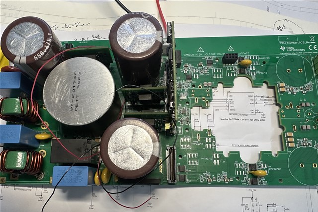
My team and I are replicating this circuit board.

When I was not connected to an auxiliary power source (12v 2A), JTAG is normal.

But when I connected the auxiliary power supply,JTAG will cease.

Could you please tell me the solution?

  • 您好,

    收到了您的案例,调查需要些时间,感您的耐心等待。

  • Before the auxiliary power supply was connected (12v2a), JTAG is normal.

    I replicated the circuit board exactly according to the schematic diagram.

    After connecting the auxiliary power supply(12v2A), JTAG has cease.

    The following errors occurred:(Error -2131 @ 0x0)
    Unable to access device register. Reset the device, and retry the operation. If error persists, confirm configuration, power-cycle the board, and/or try more reliable JTAG settings (e.g. lower TCLK).
    (Emulation package 20.2.0.3536).

    Could you please inform me as soon as possible of the reason? Is it due to a power supply issue?

  • Without connecting the auxiliary power supply, the control card operates normally and the communication is also normal.

  • I thing this could be the JTAG connection issue. Can you try with different cable. Also try adding some choke around the USB cable to filter the EMI noise. Let me know if it works.

  • ok,I'll give it a try.

  • Hi,

    I followed your instructions: replaced the USB cable, added capacitor C7:A, and connected USB_GND to GND through the wire. I tried these three methods, but all failed in the end.

    After the auxiliary power (12V 2A)was connected, JTAG was immediately interrupted.

    I noticed that this TMDSCNCD280039C controlCARD  has the following suggestions:The 5-V rail on the TMDSCNCD280039C controlCARD can be powered from an on-board USB connector or from a baseboard like the TMDSHSECDOCK. A switch device on the controlCARD automatically selects the 5-V input power source for the controlCARD without the need for user configuration. A loss of power or glitching on the baseboard 5-V power source can cause the automatic switch to disconnect from both power sources for several milliseconds. This momentary loss of power may cause a brownout condition on the MCU, triggering a device reset. To avoid this condition, ensure that the baseboard power supply remains at 0 V or 5 V during code execution.

    Could you provide me with some solutions?

    thank you.

  • May we know how you procured this TIDM-02013 hardware.

  • Hi,

     TMDSCNCD280039C,TIDM-02013,All were obtained from the ti website. Except for some differences in resistors and capacitors, the other chips are all the same.

  • Hello,

    Can you try removing the F28003x controlCard from the PMP22650 dock and try to connect. If it works, then its likely a contention issue.

    The PMP22650 HSEC connector has connections to the JTAG signals. It also has an isolator on those signals. With regards to the controlCard, I believe the isolator is overpowering the JTAG signals being driven by the debugger.

  • Hi,

    I have followed your instructions and found that as long as the auxiliary power supply(12V 2A) is turned off, the F28003x controlCard can operate normally.

    The control card has a power switching mode. I have tried all three of its settings, but none of them worked properly. As long as this auxiliary power is turned on, it will not function normally.

    Regarding the connection issue you mentioned, do you have any solutions? Are there any components on the power board that need to be removed? Because I also saw similar cases on the forum.

    thank you.

  • Hello,

    There is a resolution requiring modification to the controlCARD board:

    1. C7:A should be removed
    2. Four traces in the front and back, highlighted in red below, need to be cut. There are no important traces in the layers below, please ensure that the trace is no longer connected or the controlCARD may not connect when inserted into the PMP22650.

    Cut two traces in the front:

    Cut two traces in the back:

    There are additional changes (adding caps to help with signal integrity), but that wont be the source of this contention issue.

  • Hello,

    I can't see the two pictures you sent. Could you please resend them? Are these traces on the PCB?

    Thank you.

  • Hi

    Cut two traces in the front:

    Cut two traces in the back:

    Is it about disconnecting these four pins from the pmp22650?

    The format of the picture you sent might be incorrect. I'm actually unable to view it. Could you specify which pin you are referring to?

  • Could you please help me identify exactly which four pins they are? The picture doesn't show clearly.

    Could you please answer my question? I'm very anxious.

    Thank you.

  • Hello,

    Yes, Pins 3, 5, 6, and 8 (corresponding to TMS, TCK, TDO, and TDI) need to be disconnected to eliminate contention. 

  • Hi,

    //#define TTPLPFC_GI_PI_KP (float) 0.1//0.3496503407
    //#define TTPLPFC_GI_PI_KI (float) 0.002//0.0020000510

    //Kdc = 0.02, fz0 = 1, ISR fs = 120 kHz, fbw ~ 2 kHz at 150 V / 400 V / 100 Ohm
    //#define TTPLPFC_GI_PI_KP (float) 0.0194764
    //#define TTPLPFC_GI_PI_KI (float) 0.0537675
    //#define TTPLPFC_GI_PI_KP (float) 0.25
    //#define TTPLPFC_GI_PI_KI (float) 0.07
    #define TTPLPFC_GI_PI_KP (float) 0.3
    #define TTPLPFC_GI_PI_KI (float) 0.03
    //#define TTPLPFC_GI_PI_KI (float) 0.05

    //#define TTPLPFC_GV_PI_KP (float) 0.6004499882
    //#define TTPLPFC_GV_PI_KI (float) 0.0001000236
    #define TTPLPFC_GV_PI_KP (float) 0.6
    #define TTPLPFC_GV_PI_KI (float) 0.0001
    //
    Which one is the kp and ki for lab 2?

  • Can you confirm if this solution resolved your JTAG connectivity issues?

  • Hello, I have defined lab 1. However, during the power-on process, the ADC sampling was normal, but no 0.5 duty cycle was generated. Therefore, the output was the same as the input. Could you please tell me how to configure it?

  • As shown in the figure, the lab1 ISR has been activated. Once the counter reaches 100, the relay closes and 120V DC is connected. However, there is no voltage boost, and the output is also 120V,

    In these function definitions, I have commented out any definitions related to CLLC and enabled all functions of the PFC.

    However, there is no PWM output.

    Could you tell me how to configure it?

    thank you.

  • Since lab 2 is closed current loop current loop PI (GI_) parameters are used.

    #define TTPLPFC_GI_PI_KP (float) 0.3
    #define TTPLPFC_GI_PI_KI (float) 0.03

  • Hi,

    I am currently conducting lab 1. After debugging, the ADC is functioning normally, but there is no 0.5 pu output. The input is then sent out through this rectifier bridge. Could you please offer me some suggestions?

  • Did you check the above. May I know your observation please?