This thread has been locked.

If you have a related question, please click the "Ask a related question" button in the top right corner. The newly created question will be automatically linked to this question.

TMDXIDK5718: 上电SD卡无法启动,芯片不工作,串口打印乱码

Part Number: TMDXIDK5718

按照快速启动方法:插上评估板配套的linux sdk的sd卡,

外接电源5v,6.5A/10A供电,

接上USB  JTAG,

点击power on按钮后:

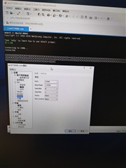
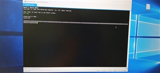
串口打印乱码(波特率设置115200),

Industrial led2、Industrial led3,STATUS LED0 ,STATUS LED1闪烁

  • 以下链接已经参考过了是吗?

    After, you power on the EVM the Status, Industrial LED2, Industrial LED3 will turn on. If the microUSB cable is pluged in then the LED corresponding to FTDI UARTtoUSB will be turned on.

    software-dl.ti.com/.../index_how_to_guides.html

    建议自己再重新烧写镜像文件再试一下,或者跑一下diag程序,测试一下外设串口有没有问题。

    software-dl.ti.com/.../Processor_SDK_Linux_create_SD_card.html

    https://software-dl.ti.com/processor-sdk-rtos/esd/docs/latest/rtos/index_board.html#diagnostics

  • 重新刷了ti-processor-sdk-linux-am57xx-evm-08_02_01_00-Linux-x86-Install.bin的系统,外接电源上电评估板仍然没有工作,,,the Status LED, Industrial LED2, Industrial LED3 闪烁,,,串口打印乱码。            

  • 会不会是板子有问题,无法给芯片供电呢

  • ccs能连上板子吗?跑一下简单的程序,如果可以的话,板子(供电)应该没问题的。

  • CCS测试无法检测到JTAG,考虑还是板子有问题呢,能否安排退回检修呢

    [Start: Texas Instruments XDS100v2 USB Debug Probe_0]

    Execute the command:

    %ccs_base%/common/uscif/dbgjtag -f %boarddatafile% -rv -o -F inform,logfile=yes -S pathlength -S integrity

    [Result]


    -----[Print the board config pathname(s)]------------------------------------

    R:\Users\wl0545\AppData\Local\TEXASI~1\CCS\
    ccs1040\0\0\BrdDat\testBoard.dat

    -----[Print the reset-command software log-file]-----------------------------

    This utility has selected a 100- or 510-class product.
    This utility will load the adapter 'jioserdesusb.dll'.
    The library build date was 'Jun 25 2021'.
    The library build time was '11:45:30'.
    The library package version is '9.4.0.00129'.
    The library component version is '35.35.0.0'.
    The controller does not use a programmable FPGA.
    The controller has a version number of '4' (0x00000004).
    The controller has an insertion length of '0' (0x00000000).
    This utility will attempt to reset the controller.
    This utility has successfully reset the controller.

    -----[Print the reset-command hardware log-file]-----------------------------

    The scan-path will be reset by toggling the JTAG TRST signal.
    The controller is the FTDI FT2232 with USB interface.
    The link from controller to target is direct (without cable).
    The software is configured for FTDI FT2232 features.
    The controller cannot monitor the value on the EMU[0] pin.
    The controller cannot monitor the value on the EMU[1] pin.
    The controller cannot control the timing on output pins.
    The controller cannot control the timing on input pins.
    The scan-path link-delay has been set to exactly '0' (0x0000).

    -----[The log-file for the JTAG TCLK output generated from the PLL]----------

    There is no hardware for programming the JTAG TCLK frequency.

    -----[Measure the source and frequency of the final JTAG TCLKR input]--------

    There is no hardware for measuring the JTAG TCLK frequency.

    -----[Perform the standard path-length test on the JTAG IR and DR]-----------

    This path-length test uses blocks of 64 32-bit words.

    The test for the JTAG IR instruction path-length failed.
    The JTAG IR instruction scan-path is stuck-at-ones.

    The test for the JTAG DR bypass path-length failed.
    The JTAG DR bypass scan-path is stuck-at-ones.

    -----[Perform the Integrity scan-test on the JTAG IR]------------------------

    This test will use blocks of 64 32-bit words.
    This test will be applied just once.

    Do a test using 0xFFFFFFFF.
    Scan tests: 1, skipped: 0, failed: 0
    Do a test using 0x00000000.
    Test 2 Word 0: scanned out 0x00000000 and scanned in 0xFFFFFFFF.
    Test 2 Word 1: scanned out 0x00000000 and scanned in 0xFFFFFFFF.
    Test 2 Word 2: scanned out 0x00000000 and scanned in 0xFFFFFFFF.
    Test 2 Word 3: scanned out 0x00000000 and scanned in 0xFFFFFFFF.
    Test 2 Word 4: scanned out 0x00000000 and scanned in 0xFFFFFFFF.
    Test 2 Word 5: scanned out 0x00000000 and scanned in 0xFFFFFFFF.
    Test 2 Word 6: scanned out 0x00000000 and scanned in 0xFFFFFFFF.
    Test 2 Word 7: scanned out 0x00000000 and scanned in 0xFFFFFFFF.
    The details of the first 8 errors have been provided.
    The utility will now report only the count of failed tests.
    Scan tests: 2, skipped: 0, failed: 1
    Do a test using 0xFE03E0E2.
    Scan tests: 3, skipped: 0, failed: 2
    Do a test using 0x01FC1F1D.
    Scan tests: 4, skipped: 0, failed: 3
    Do a test using 0x5533CCAA.
    Scan tests: 5, skipped: 0, failed: 4
    Do a test using 0xAACC3355.
    Scan tests: 6, skipped: 0, failed: 5
    Some of the values were corrupted - 83.3 percent.

    The JTAG IR Integrity scan-test has failed.

    -----[Perform the Integrity scan-test on the JTAG DR]------------------------

    This test will use blocks of 64 32-bit words.
    This test will be applied just once.

    Do a test using 0xFFFFFFFF.
    Scan tests: 1, skipped: 0, failed: 0
    Do a test using 0x00000000.
    Test 2 Word 0: scanned out 0x00000000 and scanned in 0xFFFFFFFF.
    Test 2 Word 1: scanned out 0x00000000 and scanned in 0xFFFFFFFF.
    Test 2 Word 2: scanned out 0x00000000 and scanned in 0xFFFFFFFF.
    Test 2 Word 3: scanned out 0x00000000 and scanned in 0xFFFFFFFF.
    Test 2 Word 4: scanned out 0x00000000 and scanned in 0xFFFFFFFF.
    Test 2 Word 5: scanned out 0x00000000 and scanned in 0xFFFFFFFF.
    Test 2 Word 6: scanned out 0x00000000 and scanned in 0xFFFFFFFF.
    Test 2 Word 7: scanned out 0x00000000 and scanned in 0xFFFFFFFF.
    The details of the first 8 errors have been provided.
    The utility will now report only the count of failed tests.
    Scan tests: 2, skipped: 0, failed: 1
    Do a test using 0xFE03E0E2.
    Scan tests: 3, skipped: 0, failed: 2
    Do a test using 0x01FC1F1D.
    Scan tests: 4, skipped: 0, failed: 3
    Do a test using 0x5533CCAA.
    Scan tests: 5, skipped: 0, failed: 4
    Do a test using 0xAACC3355.
    Scan tests: 6, skipped: 0, failed: 5
    Some of the values were corrupted - 83.3 percent.

    The JTAG DR Integrity scan-test has failed.

    [End: Texas Instruments XDS100v2 USB Debug Probe_0]

  • the Status LED0、LED1,Industrial LED2, Industrial LED3 一直都是白光闪烁,并没有常亮

  • 连ccs的时候SD卡有没有拔了?请确保参考以下链接的步骤:

    Connecting IDK EVM to Code Composer Studio

    https://software-dl.ti.com/processor-sdk-rtos/esd/docs/06_03_00_106/rtos/index_how_to_guides.html#tmdxidk5728-hardware-setup

    如果还是不行,关于退换货问题需要联系客服部门:

    请按照以下方式联系客户支持部门的技术部门,会有技术客服为您提供帮助。

    • 打开链接https://ticsc.service-now.com/csm
    • 点击申请新的支持下面的提交申请按钮
    • 在新打开的窗口中点击技术支持下面的创建案例按钮
    • 在打开的表格中您可以使用中文描述您的问题并且递交。递交申请时,请您提及以下信息:
      • Ti.com购买订单号
      • 需要技术鉴定EVM是否存在质量问题
      • 您是否使用免费邮箱注册myti账号
  • 连ccs的时候需要拔掉SD卡吗?上述参考链接不是专门针对TMDXIDK5718这款评估板的也能参考吗。另外技术鉴定EVM是否存在质量问题如何提供呢

  • 要拔的。

    另外技术鉴定EVM是否存在质量问题如何提供呢

    一般流程是客服会让您到英文论坛发帖进行技术鉴定,确认有问题他们应该会有后续处理流程,具体您联系客户部门就行了。

  • 连CCS的时候拔掉了SD卡,选的 Texas Instruments XDS100v2 USB Debug Probe,  IDK AM571X

    save configuration 然后 test Connetction 结果也是  The JTAG DR Integrity  scan-test has  failed.

  • 您这边不能直接技术鉴定了吗,还需要重新发一遍英文的才行吗?

  • 连CCS的时候拔掉了SD卡,选的 Texas Instruments XDS100v2 USB Debug Probe,  IDK AM571X

    save configuration 然后 test Connetction 结果也是  The JTAG DR Integrity  scan-test has  failed.

    确保操作无误确实不行的话,请联系客户支持部门。

    您这边不能直接技术鉴定了吗,还需要重新发一遍英文的才行吗?

    是的,我们的流程是这样规定的。