你好,
我该如何读取GOADC的AD值?
This thread has been locked.
If you have a related question, please click the "Ask a related question" button in the top right corner. The newly created question will be automatically linked to this question.
/**
* @file mss_main.c
*
* @brief
* MSS main implementation of the millimeter wave Demo
*
* \par
* NOTE:
* (C) Copyright 2016 Texas Instruments, Inc.
*
* Redistribution and use in source and binary forms, with or without
* modification, are permitted provided that the following conditions
* are met:
*
* Redistributions of source code must retain the above copyright
* notice, this list of conditions and the following disclaimer.
*
* Redistributions in binary form must reproduce the above copyright
* notice, this list of conditions and the following disclaimer in the
* documentation and/or other materials provided with the
* distribution.
*
* Neither the name of Texas Instruments Incorporated nor the names of
* its contributors may be used to endorse or promote products derived
* from this software without specific prior written permission.
*
* THIS SOFTWARE IS PROVIDED BY THE COPYRIGHT HOLDERS AND CONTRIBUTORS
* "AS IS" AND ANY EXPRESS OR IMPLIED WARRANTIES, INCLUDING, BUT NOT
* LIMITED TO, THE IMPLIED WARRANTIES OF MERCHANTABILITY AND FITNESS FOR
* A PARTICULAR PURPOSE ARE DISCLAIMED. IN NO EVENT SHALL THE COPYRIGHT
* OWNER OR CONTRIBUTORS BE LIABLE FOR ANY DIRECT, INDIRECT, INCIDENTAL,
* SPECIAL, EXEMPLARY, OR CONSEQUENTIAL DAMAGES (INCLUDING, BUT NOT
* LIMITED TO, PROCUREMENT OF SUBSTITUTE GOODS OR SERVICES; LOSS OF USE,
* DATA, OR PROFITS; OR BUSINESS INTERRUPTION) HOWEVER CAUSED AND ON ANY
* THEORY OF LIABILITY, WHETHER IN CONTRACT, STRICT LIABILITY, OR TORT
* (INCLUDING NEGLIGENCE OR OTHERWISE) ARISING IN ANY WAY OUT OF THE USE
* OF THIS SOFTWARE, EVEN IF ADVISED OF THE POSSIBILITY OF SUCH DAMAGE.
*/
/** @mainpage Millimeter Wave (mmw) Demo for XWR16XX
*
* @section intro_sec Introduction
*
* @image html toplevel.png
*
* The millimeter wave demo shows some of the capabilities of the XWR16xx SoC
* using the drivers in the mmWave SDK (Software Development Kit).
* It allows user to specify the chirping profile and displays the detected
* objects and other information in real-time.
*
* Following is a high level description of the features of this demo:
* - Be able to specify desired chirping profile through command line interface (CLI)
* on a UART port or through the TI Gallery App - **mmWave Demo Visualizer** -
* that allows user to provide a variety of profile configurations via the UART input port
* and displays the streamed detected output from another UART port in real-time,
* as seen in picture above.
* - Some sample profile configurations have been provided in the demo directory that can be
* used with CLI directly or via **mmWave Demo Visualizer**:
* @verbatim
mmw/profiles/profile_2d.cfg
mmw/profiles/profile_2d_srr.cfg
mmw/profiles/profile_heat_map.cfg
@endverbatim
* - Do 1D, 2D, CFAR and Azimuth processing and stream out velocity
* and two spatial coordinates (x,y) of the detected objects in real-time.
* The demo can also be configured to do 2D only detection (velocity and x,y coordinates).
* - Various display options besides object detection like azimuth heat map and
* Doppler-range heat map.
* - Illustrates how to configure the various hardware entities (
* EDMA, UART) in the AR SoC using the driver software.
*
* @section limit Limitations
*
* - Because of UART speed limit (< 1 Mbps), the frame time is more restrictive.
* For example, for the azimuth and Doppler heat maps for 256 FFT range and
* 16 point FFT Doppler, it takes about 200 ms to transmit.
* - Present implementation in this demo can resolve up to two objects in the azimuth
* dimension which have the same range and same velocity.
* - Code will give an error if the requested memory in L3 RAM exceeds its size
* (@ref SOC_XWR16XX_DSS_L3RAM_SIZE) due to particular combination of CLI configuration parameters.
* - For most boards, a range bias of few centimeters has been observed. User can estimate
* the range bias on their board and correct using the calibration procedure
* described in @ref calibration.
*
* @section tasks System Details
* The millimeter wave demo runs on both R4F (MSS) and C674x (DSS).
* System startup is described in the following diagram:
*
* @image html system_startup.png "System Startup"
*
*
* @subsection mss_tasks Software Tasks on MSS
* The following (SYSBIOS) tasks are running on MSS:
* - @ref MmwDemo_mssInitTask. This task is created and launched by @ref main and is a
* one-time initialization task that performs the following sequence:
* -# Initializes drivers (\<driver\>_init).
* -# Initializes the MMWave module (MMWave_init)
* -# Creates/launches the following tasks (the @ref CLI_task is launched indirectly by
* calling @ref CLI_open).
* - @ref MmwDemo_mmWaveCtrlTask. This task is used to provide an execution context
* for the mmWave control, it calls in an endless loop the MMWave_execute API.
* - @ref MmwDemo_mssCtrlPathTask. The task is used to process data path events coming
* from the @ref CLI_task or start/stop events coming from @ref SOC_XWR16XX_GPIO_1 button on
* EVM. It signals the start/stop completion events back to @ref CLI_task.
* - @ref CLI_task. This CLI task takes user commands and posts events to the @ref MmwDemo_mssCtrlPathTask.
* In case of start/stop commands, it waits for the completion events from @ref MmwDemo_mssCtrlPathTask and
* on success, it toggles the LED @ref SOC_XWR16XX_GPIO_2.
* - @ref MmwDemo_mboxReadTask. This task handles mailbox messages received from DSS.
*
* @subsection dss_tasks Software Tasks on DSS
*
* The following four (SYSBIOS) tasks are running on DSS:
* - @ref MmwDemo_dssInitTask. This task is created/launched by main (in dss_main.c) and is a
* one-time active task that performs the following sequence:
* -# Initializes drivers (\<driver\>_init).
* -# Initializes the MMWave module (MMWave_init)
* -# Creates/launches the other three tasks.
* - @ref MmwDemo_mboxReadTask. This task handles mailbox messages received from MSS.
* - @ref MmwDemo_dssMMWaveCtrlTask. This task is used to provide an execution
* context for the mmWave control, it calls in an endless loop the MMWave_execute API.
* - @ref MmwDemo_dssDataPathTask. The task performs in real-time:
* - Data path processing chain control and (re-)configuration
* of the hardware entities involved in the processing chain, namely EDMA.
* - Data path signal processing such as range, Doppler and azimuth DFT,
* object detection, and direction of arrival calculation.
* - Transfers detected objects to the HS-RAM shared memory and informs MSS that the data
* is ready to be sent out to through the UART output port.
* For format of the data on UART output port, see @ref MmwDemo_dssSendProcessOutputToMSS.
* The UART transmission is done on MSS.
*
* The task pends on the following events:
* - @ref MMWDEMO_CONFIG_EVT. This event is posted by @ref MmwDemo_dssMmwaveConfigCallbackFxn
* which in called by MMWAVE_ API triggered when MSS issues MMWAVE_config
* - @ref MMWDEMO_BSS_STOP_COMPLETE_EVT. This event is posted by @ref MmwDemo_dssMmwaveEventCallbackFxn when
* the Frame Stop asynchronous event is received. Details as follows:
* Initially MSS receives the CLI sensorStop command and issues a stop command to BSS.
* Once BSS fully stops the frame processing, BSS sends a "Frame Stopped Asynchronous event" to MSS.
* MSS then forwards the "Frame Stopped Asynchronous event" to DSS, where
* it is handled by @ref MmwDemo_dssMmwaveEventCallbackFxn.
* This event causes DSS to go in @ref MmwDemo_DSS_STATE_STOP_PENDING state.
* If DSS received the "Frame Stopped Asynchronous event" after the inter-frame processing is completed,
* it will post MMWDEMO_STOP_COMPLETE_EVT.
* Otherwise, it will wait to finish the inter-frame processing before posting MMWDEMO_STOP_COMPLETE_EVT.
* See MMWDEMO_STOP_COMPLETE_EVT event below for more details.
* - @ref MMWDEMO_FRAMESTART_EVT. This event originates from BSS firmware
* and indicates the beginning of the radar frame. It is posted by interrupt
* handler function @ref MmwDemo_dssFrameStartIntHandler.
* - @ref MMWDEMO_CHIRP_EVT. This event originates from BSS firmware and
* indicates that the ADC buffer, (ping or pong) is filled with ADC samples.
* It is posted by @ref MmwDemo_dssChirpIntHandler.
* - @ref MMWDEMO_START_EVT. This event is posted by @ref MmwDemo_dssMmwaveStartCallbackFxn when
* MMWave_start is called from MSS (on CLI sensorStart 0 command which means starts with
* no reconfiguration)
* - @ref MMWDEMO_STOP_COMPLETE_EVT. This event is posted either when the MMWDEMO_BSS_STOP_COMPLETE_EVT
* is received after the inter-frame processing has ended or when the ongoing active frame finishes sending data over UART.
* This event now moves the DSS to MmwDemo_DSS_STATE_STOP state and executes @ref MmwDemo_dssDataPathStop
* which further sends @ref MMWDEMO_DSS2MSS_STOPDONE message back to MSS.
*
*
* @section datapathtop Data Path
* @subsection datapath Data Path - Overall
* @image html datapath_overall.png "Top Level Data Path Processing Chain"
* \n
* \n
* @image html datapath_overall_timing.png "Top Level Data Path Timing"
*
* As seen in the above picture, the data path processing consists of:
* - Processing during the chirps as seen in the timing diagram. This
* consists of
* - 1D (range) FFT processing performed by C674x that takes input from
* multiple receive antennas from the ADC buffer for every some number of chirps
* (corresponding to the chirping pattern on the transmit antennas), and
* - transferring output into the L3 RAM by EDMA. More details
* can be seen in @ref data1d
* - Processing during the idle or cool down period of the RF circuitry following the chirps
* until the next chirping period, shown as "Inter frame processing time" in the timing diagram.
* This processing consists of:
* - 2D (velocity) FFT processing performed by C674x that reads input from 1D output in L3 RAM in a
* transposed manner (using EDMA) and performs
* FFT to give a (range,velocity) matrix in the L3 RAM. The processing also includes the CFAR detection in Doppler direction.
* More details can be seen in @ref data2d.
* - CFAR detection in range direction using mmWave library.
* - Peak Grouping if enabled.
* - Direction of Arrival (Azimuth) Estimation. More details can be seen at
* @ref dataAngElev and @ref dataXYZ
* @subsubsection advanced Advanced Frame - Sub Frame Processing
* @image html datapath_overall_timing_subframe.png "Top Level Data Path Timing for sub-frames"
* \n
* \n
* In advanced frame mode, sub-frame processing is supported for which the datapath
* is essentially same as described in @ref datapath except that there is sub-frame switching
* related processing required to prepare for next sub-frame as seen in above diagram. The details
* of what is involved in sub-frame switching are described in @ref subFrameSwitching.
* The data path for each sub-frame is independent of other sub-frames i.e there is no
* combining of information across sub-frames - each sub-frame's results are sent out
* to the host after the completion of its data path processing in real-time.
*
* @subsection antConfig Antenna Configurations
* The following figure shows antenna layout as seen from the front of
* the EVM xWR16xx board alongside the x,y coordinate convention.
* @image html antenna_design.png "AWR16xx Antenna layout"
*
* As seen in figures below, the millimeter wave demo supports two antenna configurations:
* - Single transmit antenna and four receive antennas.
* - Two transmit antennas and four receive antennas. Transmit antennas Tx1 and Tx2
* are horizontally spaced at d = 2 Lambda, with their transmissions interleaved in
* a frame
* @image html antenna_layout_simo.png "Single Tx Antenna Configuration"
* \n
* @image html antenna_layout_mimo.png "TDM-MIMO Antenna Configuration"
* \n
*
* Both configurations allow for azimuth estimation.
*
* @subsection data1d Data Path - 1st Dimension FFT Processing
* @image html datapath_1d_tdm_mimo.png "Data Path 1D for TDM-MIMO configuration"
* \n
*
* Above picture illustrates 1D chirp processing for the case with one chirp (interrupt) event
* for every two chirps and two
* transmit antennas, (TDM-MIMO case), as mentioned in @ref antConfig.
* There are 4 rx antennas, the samples of which are color-coded and labeled
* as 1,2,3,4 with unique coloring for each of chirps that are processed
* in ping-pong manner. The 1D FFT chirp processing is triggered by
* hardware chirp event generated when the ADC
* has samples to process in the ADC buffer Ping or Pong memories. The hardware event
* triggers the registered chirp event interrupt handler function @ref MmwDemo_dssChirpIntHandler,
* that in turn posts @ref MMWDEMO_CHIRP_EVT to @ref MmwDemo_dssDataPathTask. The task initiates EDMA
* transfer of rx antenna samples in a ping pong manner to parallelize C674x processing
* with EDMA data transfer from ADC buffer to L2 memory.
* The processing includes FFT calculation using DSP library function with
* 16-bit input and output precision. Before FFT calculation, a Blackman window
* is applied to ADC samples using mmwlib library function. The calculated 1D
* FFT samples are EDMA transferred to the radar cube
* matrix in L3 memory. One column of the radar cube matrix contains 1D-FFT
* samples of chirps corresponding to the two transmit antennas and in this (TDM) case,
* all chirps corresponding to Tx1 are stored consecutively followed by those corresponding
* to Tx2. The reason for storing in this way instead of time of arrival order (Tx1,Tx2,Tx1,Tx2..)
* is to prevent EDMA jump for 1D output and 2D input from exceeding the EDMA jump limit.
* The EDMA jumps (source and destination B/C indices) are 16-bit signed, so when
* number of range bins is 1024 and number of receive antennas is 4, the jump becomes
* 1024*4*4(bytes/sample)*2(Tx1,Tx2 order) = 32768 which is -32768 as signed 16-bit.
* While the jump in 1D output can be overcome by setting the destination address in the compute
* loop every chirp output EDMA trigger (which is not too significant burden in cycles),
* the 2D cannot be overcome this way without breaking the very purpose of EDMA-CPU parallelism
* because the source address would have to be reprogrammed every sample!
* The jump is halved (16384) when storing all Tx1 consecutively followed by all Tx2 consecutively.
* Picture below illustrates the shape of radar cube matrix
* for one Tx antenna configuration, where one column contains 1D FFT samples of one chirp.
*
* @image html datapath_1d_simo_radar_cube.png "Radar cube matrix for single Tx antenna configuration"
* \n
*
* The timing diagram of chirp processing is illustrated in figure below.
* @image html datapath_1d_timing.png "Data Path 1D timing diagram"
* \n
*
* @subsubsection calibDC_Range Antenna coupling signature removal
*
* @image html antenna_coupling_signature_removal.png "Antenna coupling signature removal"
*
* Antenna coupling signature dominates the range bins close to the radar.
* These are the bins in the range FFT output located around DC.
* This feature is under user control in terms of
* enable/disable and start/end range bins through a CLI command called calibDcRangeSig.
* During measurement (when the CLI command is issued with feature enabled),
* each of the specified range bins for each of the virtual antennas are accumulated
* over the specified number of chirps and at the end of the period, the average
* is computed for each bin/antenna combination for removal after the measurement
* period is over. Note that the number of chirps to average must be power of 2.
* It is assumed that no objects are present
* in the vicinity of the radar during this measurement period. After measurement
* is done, the removal starts for all subsequent frames during which each
* of the bin/antenna average estimate is subtracted from the corresponding received samples
* in real-time for subsequent processing.
*
* @subsection data2d Data Path - 2nd Dimension FFT Processing
* The 2D processing consists of the following steps:
* -# For each range bin it performs:
* - Static clutter removal if enabled. The mean value of the input samples to the
* 2D-FFT is subtracted from the samples,
* - Windowing - samples are multiplied by a window function,
* - 2D-FFT on the samples of 1D-FFT output across chirps (samples are transposed
* by the EDMA before 2D FFT can be performed),
* - log2 magnitude of the output,
* - accumulation across all Rx antennas,
* - transfer of accumulated values to detection matrix in L3 using EDMA,
* - CFAR pre-detection in Doppler direction and saving of Doppler
* indices of detected objects for the final CFAR detection in the range direction.
*
* -# Final CFAR detection in range direction at Doppler indices at which
* objects were detected in previous step
* -# Peak grouping. Grouping options are specified by CLI CFAR configuration function and can be
* - in both range and Doppler direction,
* - only in range,
* - only in Doppler direction, or
* - none.
* \n
* The 2D processing is shown in figures below.
*
* @image html datapath_2d_detailed_part1.png "2D-FFT Processing - Calculation of Detection Matrix and CFAR in Doppler direction"
* \n
* \n
* @image html datapath_2d_timing.png "2D-FFT Processing - Calculation of Detection Matrix and CFAR in Doppler direction - timing diagram"
* \n
* \n
* @image html datapath_2d_detailed_part2.png "CFAR in range direction and peak grouping"
*
* @subsubsection peakGrouping Peak grouping
* Two peak grouping schemes are implemented:
* -# Peak grouping based on peaks of the neighboring bins read from detection
* matrix. For each CFAR detected peak, listed in @ref MmwDemo_DSS_DataPathObj::detObj2DRaw,
* it checks if the peak is greater than its neighbors. If this is true, the
* peak is copied to the output list of detected objects
* @ref MmwDemo_DSS_DataPathObj::detObj2D. The neighboring peaks that are used
* for checking are taken from the detection matrix @ref MmwDemo_DSS_DataPathObj::detMatrix
* and are copied into 3x3 kernel regardless of whether they are CFAR detected or not.
* -# Peak grouping based on peaks of neighboring bins that are CFAR detected.
* For each detected peak the function checks if the peak is greater than its
* neighbors. If this is true, the peak is copied to the output list of
* detected objects. The neighboring peaks that are used for checking are
* taken from the list of CFAR detected objects, (not from the detection matrix),
* and are copied into 3x3 kernel that has been initialized to zero for each
* peak under test. If the neighboring peak has not been detected by CFAR,
* it is not copied into the kernel.
*
* Peak grouping schemes are illustrated in two figures below. The first figure,
* illustrating the first scheme, shows how the two targets (out of four) can
* be discarded and not presented to the output. For these two targets (at range
* indices 3 and 17 in figure below) the CFAR detector did not detect the highest
* peak of the target, but only some on the side, and these side peaks are discarded.
* The second figure, illustrating the second scheme, shows that all four targets
* are presented to the output, one peak per target, with the targets at range
* indices 3 and 17 represented with side peaks.
*
* @image html peak_grouping_based_on_detection_matrix.png "Peak grouping based on neighboring peaks from detection matrix"
* \n
* @image html peak_grouping_based_on_cfar_detected_peaks.png "Peak grouping based on on neighboring CFAR detected peaks"
* \n
* @subsection dataAngElev Data Path - Direction of Arrival FFT Calculation
* Because L3 memory is limited in size, the radar cube matrix stores only the
* 1D-FFT in 16-bit precision. Because of this, azimuth FFT calculation requires
* repeated 2D FFT calculation. Since for each detected object, we need 2D FFT at a
* single bin, instead of recalculating 2D-FFT, we calculate single point DFT
* at the bin index of each detected object. This calculation is repeated for each received antenna.
*
* Compensation for the Doppler phase shift in the angle estimation is performed on the virtual
* antennas (symbols corresponding to the second Tx antenna in case of TDM-MIMO
* configuration). These symbols are rotated by half of the estimated Doppler
* phase shift between subsequent chirps from the same Tx antenna.
* The Doppler shift is calculated using the lookup table @ref MmwDemo_DSS_DataPathObj::azimuthModCoefs
* Refer to the pictures below.
* @anchor Figure_doppler
* @image html angle_doppler_compensation_awr16.png "Figure_doppler: Doppler Compensation"
*
* Currently the size of Azimuth FFT is hardcoded and defined by @ref MMW_NUM_ANGLE_BINS.
* The FFT is calculated using DSP lib function DSP_fft32x32. The output of the
* function is magnitude squared and the values are stored in floating point format.
*
* @image html datapath_azimuth_fft.png "Direction of arrival calculation"
*
*
* @subsection dataXYZ Data Path - (X,Y) Estimation
* The (x,y) estimation is calculated in the function @ref MmwDemo_XYestimation.
* \anchor Figure_geometry
* @image html coordinate_geometry.png "Figure A: Coordinate Geometry"
* \n
* \anchor Figure_wx
* @image html coordinate_geometry_wx.png "Figure wx"
* \ref Figure_geometry shows orientation of x,y axes with respect to the sensor/antenna positions.
* The objective is to estimate the (x,y) coordinates of each detected object.
* \f$w_x\f$ is the phase difference between consecutive receive azimuth antennas of the 2D FFT.
* The phases for each antenna are shown in the \ref Figure_doppler.
* \ref Figure_wx shows that the distance AB which represents the relative
* distance between wavefronts intersecting consecutive azimuth
* antennas is \f$AB = \frac{\lambda}{2} \sin (\theta)\f$.
* Therefore \f$w_x = \frac{2\pi}{\lambda} \cdot AB\f$, and therefore \f$w_x = \pi \sin (\theta)\f$.
* Note that the phase of the left-ward antenna is advanced compared to the right-ward
* antenna and antenna indices increment from right to left (which is the order in ADCbuf and all
* of processing) so phase increments as \f$+w_x\f$.
* For a single obstacle, the signal at the 8 azimuth antennas will be (\f$A_1\f$ and \f$\psi\f$ are the arbitrary starting
* amplitude/phase at the first antenna):
* \f[
* A_1 e^{j\psi} [ 1 \; e^{jw_x} \; e^{j2w_x} \; e^{j3w_x} \; e^{j4w_x} \; e^{j5w_x} \; e^{j6w_x} \; e^{j7w_x} ]
* \f]
*
* An FFT of the above signal will yield a peak at \f$w_x\f$ .
* If \f$k_{MAX}\f$ is the index of the peak in log magnitude FFT represented as
* signed index in range \f$[-\frac{N}{2}, \frac{N}{2}-1]\f$, then \f$ w_x \f$ will be
* \f[
* w_x = \frac{2\pi}{N}k_{MAX}
* \f]
*
* Calculate range (in meters) as:
* \f[
* R=k_r\frac{c \cdot F_{SAMP}}{2 \cdot S \cdot N_{FFT}}
* \f]
* where, \f$c\f$ is the speed of light (m/sec), \f$k_r\f$ is range index,
* \f$F_{SAMP}\f$ is the sampling frequency (Hz),
* \f$S\f$ is chirp slope (Hz/sec), \f$N_{FFT}\f$ is 1D FFT size.
* Based on above calculations of \f$R\f$ and \f$w_x\f$, the \f$(x,y)\f$ position of the object
* can be calculated as seen in the \ref Figure_geometry,
* \f[
* x = R\sin(\theta) = R\frac{w_x}{\pi}, y = \sqrt{R^2-x^2}
* \f]
* The computed \f$(x,y)\f$ and azimuth peak for each object are populated in their
* respective positions in @ref MmwDemo_DSS_DataPathObj::detObj2D. Note the azimuth
* peak (magnitude squared) replaces the previous CFAR peak (sum of log magnitudes) in the structure.
* To be able to detect two objects at the same range-doppler index but at different angle,
* search for the 2nd peak in the azimuth FFT and compare its height relative to the first peak height,
* and if detected, create new object in the list with the same range/Doppler
* indices, and repeat above steps to calculate (x,y) coordinates. To enable/disable
* the two peak detection or to change the threshold for detection, refer to
* @ref MMWDEMO_AZIMUTH_TWO_PEAK_DETECTION_ENABLE and @ref MMWDEMO_AZIMUTH_TWO_PEAK_THRESHOLD_SCALE.
*
* @subsection velocityDisambiguation Velocity disambiguation
* A simple technique for velocity disambiguation is implemented. It corrects target velocities up to \f$2v_{max}\f$, and
* allows for correct calculation of X/Y coordinates for target velocities even greater than \f$2v_{max}\f$.
* The technique consists of the following steps applied after the CFAR detection phase.
* For each detected point, assuming doppler correction of virtual antennas is already done:
* -# Copy the doppler corrected antenna data A into the upper address area
* (labeled B in the figure below) of the azimuthIn.
* This is done because the DSPlib FFT function overwrites the input buffer with
* reversed index and we would need to later compute the FFT on sign flipped symbols
* corresponding to Tx2.
* -# Calculate azimuth FFT (in area A) and compute the magnitude squared of the FFT output.
* -# Save result azimuthMagSqr to set 0, "uncorrected set", (see figure below).
* -# Flip the signs of the symbols corresponding to Tx2 antenna transmission in area B.
* Copy B to A and zero pad.
* -# Repeat step 4.
* -# Save result azimuthMagSqr to set 1, "corrected set".
* -# Search for maximum over both sets, and select the set where the maximum occurred.
* -# If the maximum occurred in "corrected set", correct the estimated velocity as:
*
* \f$ v_{corr} = v_{est} + 2v_{max}\f$ (if \f$v_{est} < 0\f$)
*
* \f$ v_{corr} = v_{est} - 2v_{max}\f$ (if \f$v_{est} > 0\f$)
*
* otherwise no correction is required.
* -# Calculate X/Y coordinates using index \f$i_{max}\f$ from the selected set.
*
* @image html datapath_azimuth_fft_extnd_max_vel.png "Extending maximum velocity - data path"
*
* Figure below illustrates this technique on one example with a target moving from the sensor at
* positive azimuth angle at a speed less than Vmax (case a), and at the
* speed greater than Vmax (case b). Figure shows 2D-FFT antenna symbols for 3 consecutive chirps: n, n+1 and n+2 (blue, green and red dots).
* The symbols of the chirp n and n+1 are used for azimuth FFT calculation.
* The Doppler shift, the angle \f$\psi_{true}\f$ between chirps n and n+2, (successive chirps of the same Tx antenna),
* is estimated from 2D-FFT as \f$\psi_{est}\f$. In case a, \f$\psi_{true} < \pi\f$,
* and \f$\psi_{est} \approx \psi_{true}\f$. In case b, \f$\psi_{true} > \pi\f$, (Doppler velocity is aliased),
* and \f$\psi_{est}\f$ is estimated as a negative value, (target approaching the sensor). Doppler compensation rotates the symbols of chirp n+1
* by \f$-\psi_{est}/2\f$ to align them with the symbols of chirp n. The azimuth FFT is calculated on these symbols,
* and the output is placed to set 0. The symbols of the chirp n+1 are then sign flipped,
* and the azimuth FFT is again calculated and the output is placed to set 1.
* In case a, V<Vmax, the maximum peak in the FFT output in set 0 is larger than in set 1, as opposed in case b, V>Vmax,
* where the maximum peak in FFT output in set 1 is larger than in set 0.
*
* @image html extend_max_velocity.png "Example of target moving from sensor under angle at V<Vmax (Case a) and V>Vmax (Case b)"
*
* @subsection nearFieldCorrection Near Field Correction
* @subsubsection nearFieldProblem Problem Statement and Algorithm Description
* @image html near_field_geometry.png "Near Field Geometry"
*
* It was assumed in @ref dataXYZ that the object was located in the far field so that
* the rays between the object and the multiple TX/RX antennas are parallel.
* However for very close by objects this assumption (of parallel lines) is not
* valid as seen in the above figure and can induce a significant phase error
* when processed using regular FFT techniques. It can be shown that:
* - The phase error is most pronounced in the phase difference between the
* path from Tx1(C)->object(O)->Rx4(D) (red lines) and Tx2(A)->object(O)->Rx1(E) (green lines).
* This corresponds to the phase difference between virtual antenna 4 and 5
* - The phase error decreases as the range of the object increases.
* - For a fixed range, the phase error is most severe for bore-sight objects
* and decreases to zero at grazing angles.
*
* This phase error manifests in a spurious peak in the azimuth FFT which results
* in ghost object detection when multi object beam forming feature is enabled.
* In order to mitigate this error, the phase error between the physical and virtual
* sets of antennas needs to be corrected based on the geometry and the range at
* which the object has been detected. This is done in the following manner:
*
* Let x be the 1x8 vector corresponding to the 8 virtual antennas.
* Let F denote the 64-point FFT of x; i.e F=fftshift (fft(x,64));
* Similarly let \f$F_1\f$ and \f$F_2\f$ denote the 64-point FFT锟絪 of x(1:4) and x(5:8).
* Then it can be shown that:
* \f[
* F(k) = F_1(k) + F_2(k) e^{-j 2 \pi k 4/64}; -32 \leq k \leq 31;
* \f]
* The above equation can be modified to incorporate the effect of the near-field
* induced phase error (which occurs at the boundary between the virtual antennas
* corresponding to TX1 and TX2). The modified equation is:
* \f[
* F(k) = F_1(k) + F_2(k) e^{-j 2 \pi k 4/64} e^{- j \phi(k,r)}; -32 \leq k \leq 31;
* \f]
* where \f$\phi(k,r)\f$ is the near-field induced phase error which depends
* on the angle \f$k\f$ and range \f$r\f$. This quantity can be computed from the
* geometry in the above figure as follows:
*
* \f[
* \triangle OBC: tx1 = \sqrt{r^2 + \overline{\rm BC}^2 - 2 r \overline{\rm BC} \cos(\pi / 2 - \theta)}
* \f]
* \f[
* \triangle OBA: tx2 = \sqrt{r^2 + \overline{\rm BA}^2 - 2 r \overline{\rm BA} \cos(\pi / 2 + \theta)}
* \f]
* \f[
* \triangle OBD: rx4 = \sqrt{r^2 + \overline{\rm BD}^2 - 2 r \overline{\rm BD} \cos(\pi / 2 - \theta)}
* \f]
* \f[
* \triangle OBE: rx1 = \sqrt{r^2 + \overline{\rm BE}^2 - 2 r \overline{\rm BE} \cos(\pi / 2 - \theta)}
* \f]
*
* With \f$theta = \arcsin(2k/64)\f$, the above simplifies to:
*
* \f[
* tx1 = \sqrt{r^2 + \overline{\rm BC}^2 - r k (\overline{\rm BC}/16)}
* \f]
* \f[
* tx2 = \sqrt{r^2 + \overline{\rm BA}^2 - r k(-\overline{\rm BA}/16)}
* \f]
* \f[
* rx4 = \sqrt{r^2 + \overline{\rm BD}^2 - r k(\overline{\rm BD}/16)}
* \f]
* \f[
* rx1 = \sqrt{r^2 + \overline{\rm BE}^2 - r k(\overline{\rm BE}/16)}
* \f]
*
* Note that \f$\overline{\rm BC}\f$, \f$\overline{\rm BA}\f$,
* \f$\overline{\rm BD}\f$, \f$\overline{\rm BE}\f$
* are constants and therefore above calculations involve
* 4*(3 multiplications + 2 additions/subtractions + square root).
*
* As mentioned in @ref dataXYZ, for far field the phase difference between
* consecutive antennas is \f$w_x = \pi \sin(\theta)\f$. So the phase error
* is calculated as:
* \f{eqnarray*}{
* \phi(k,r) &=& \frac{2 \pi}{\lambda} \{(tx2 + rx1) - (tx1 + rx4)\} - \pi \sin(\theta) \\
* &=& \frac{2 \pi}{\lambda} \{(tx2 + rx1) - (tx1 + rx4)\} - \pi k / 32
* \f}
*
* @subsubsection nearFieldImplementation Implementation Details
* @image html near_field.png "Near Field Implementation"
*
* Referring to the figure above, for each detected point, assuming doppler correction
* of virtual antennas is already done:
* -# Copy the antenna data corresponding to Tx2 to the upper address area
* (labeled B in the figure) of the azimuthIn and zero-pad between
* A (data for Tx1) and B. The purpose of this step is to preserve the Tx2 symbols
* for the next computation. Compute the FFT of the first 64 samples of azimuthIn
* and store in lower address (Set 0 in the picture) of azimuthOut. This is the \f$F_1(k)\f$.
* -# Copy the Tx2 data stored at the upper address from above step into
* the position B shown in the lower path, which is basically restoring
* B back to its original position. Zero-pad the first 4 antennas (corresponding to Tx1)
* and zero-pad the remaining FFT input data after B. Compute the FFT of the
* first 64 samples of azimuthIn and store in upper address (Set 1 in the picture)
* of azimuthOut. This will be \f$F_2(k) e^{-j 2 \pi k 4/64}\f$.
* -# Apply the correction \f$e^{- j \phi(k,r)}\f$ on Set 1 over all \f$k \in [-32,31)\f$
* and add with Set 0 in place i.e output of the sum will replace Set 0.
* -# Proceed to do the rest of the azimuth calculations (magnitude square etc).
*
* NOTE:
* -# The range bias estimated from the calibration procedure is subtracted from the
* range at which object is detected before calculating the phase correction.
* The function to estimate the phase correction is @ref MmwDemo_nearFieldCorrection.
* -# The near field correction is currently in exclusion with velocity disambiguation
* because of implementation complexities and also because it is unlikely to have
* objects at high velocities in the near field.
*
* @subsubsection nearFieldintereface User Interface
*
* A CLI command "nearFieldCfg" has been provided with parameters to enable/disable
* the feature and provide start and end range index over which the feature
* is to be activated. The phase error is highest at boresight (\f$\theta = 0\f$).
* The following data at the boresight, which can be computed
* using the formulae in @ref nearFieldProblem, can be used as a guidance to
* decide the maximum range up to which to enable the feature.
*
* | Distance (cm) | Phase Error (degrees) |
* |---------------|-----------------------|
* | 5 | 177.8 |
* | 10 | 90.3 |
* | 20 | 45.3 |
* | 40 | 22.7 |
* | 80 | 11.4 |
* | 100 | 9.1 |
* | 200 | 4.5 |
* | 400 | 2.3 |
* | 1000 | 0.9 |
*
* NOTE:
* -# The range index does not exclude the range bias.
* E.g if the range bias is 6 cm and the range step is 2 cm,
* then 4 cm from the sensor will be (6+4)/2 or 5 range bins or range index of 4.
* -# Because of several computations involved in the near field correction
* for each detected point in the near field
* (most notably 64*(4 square root + 1 sin + 1 cosine)),
* the DSP will consume non-trivial MIPS for this feature.
* Presently it takes about 35000 cycles per detected point in the
* enabled near field range which is 58 us (at 600 MHz DSP speed).
* -# Because of reasons not yet fully understood, the feature does not work
* reliably below about 5 cm and therefore is recommended to be disabled below
* this range (using the start index parameter of the configuration).
* -# The near field correction is not applied on azimuth-range heatmap data
* shipped out of the target.
*
*
* @subsection subFrameSwitching Sub-frame Switching for Advanced Frame
* There is some compute overhead for switching sub-frames beyond the book-keeping
* aspects for the data path object (which are multi-instantiated).
* Because of the potential resource constraints of EDMA (channels, params etc),
* and memory limitations, some computations are redone for each sub-frame depending on its
* configuration. These are:
* - Reconfiguration of ADCbuf driver - @ref MmwDemo_dssDataPathConfigAdcBuf
* - Reprogramming of the EDMA channels and Param sets - @ref MmwDemo_dataPathInitEdma
* - Regeneration of tables for FFT (twiddle tables), single-point DFT and
* FFT window - @ref MmwDemo_dataPathConfigFFTs. This regeneration is particularly
* high in cycles if not optimized so certain optimizations
* were performed to efficiently generation these tables.
*
* One can see the cycles related to switching to the next sub-frame
* by examining in real-time mode
* the element @ref MmwDemo_timingInfo::subFrameSwitchingCycles
* in the data path object instance corresponding to the current sub-frame.
* Note that the buffer layout as described in section @ref edma is calculated during configuration
* time for all sub-frames corresponding to their configurations and so does not need
* to be part of sub-frame switching, because the memory savings related to not
* multiplying the buffer pointer storage for all sub-frames is modest.
* The above functions are called as part of a convenient reconfiguration
* function - @ref MmwDemo_dssDataPathReconfig.
*
* @subsection output Output information sent to host
* Output packets with the detection information are sent out every frame
* through the UART. Each packet consists of the header @ref MmwDemo_output_message_header_t
* and the number of TLV items containing various data information with
* types enumerated in @ref MmwDemo_output_message_type_e. The numerical values
* of the types can be found in @ref mmw_output.h. Each TLV
* item consists of type, length (@ref MmwDemo_output_message_tl_t) and payload information.
* The structure of the output packet is illustrated in the following figure.
* Since the length of the packet depends on the number of detected objects
* it can vary from frame to frame. The end of the packet is padded so that
* the total packet length is always multiple of 32 Bytes.
*
* @image html output_packet_uart.png "Output packet structure sent to UART"
*
* The following subsections describe the structure of each TLV.
*
* @subsubsection tlv1 List of detected objects
* Type: (@ref MMWDEMO_OUTPUT_MSG_DETECTED_POINTS)
*
* Length: (size of @ref MmwDemo_output_message_dataObjDescr_t) + (Number of detected objects) x (size of @ref MmwDemo_detectedObj_t)
*
* Value: List descriptor (@ref MmwDemo_output_message_dataObjDescr_t) followed
* by array of detected objects. The information of each detected object
* is stored in structure @ref MmwDemo_detectedObj_t. When the number of
* detected objects is zero, this TLV item is not sent. The whole detected objects
* TLV structure is illustrated in figure below.
*
* @image html detected_objects_tlv.png "Detected objects TLV"
*
* @subsubsection tlv2 Range profile
* Type: (@ref MMWDEMO_OUTPUT_MSG_RANGE_PROFILE)
*
* Length: (Range FFT size) x (size of uint16_t)
*
* Value: Array of profile points at 0th Doppler (stationary objects).
* In XWR16xx the points represent the sum
* of log2 magnitudes of received antennas, expressed in Q8 format.
* In XWR14xx the points represent the average of log2 magnitudes of
* received antennas, expressed in Q9 format.
*
* @subsubsection tlv3 Noise floor profile
* Type: (@ref MMWDEMO_OUTPUT_MSG_NOISE_PROFILE)
*
* Length: (Range FFT size) x (size of uint16_t)
*
* Value: This is the same format as range profile but the profile
* is at the maximum Doppler bin (maximum speed
* objects). In general for stationary scene, there would be no objects or clutter at
* maximum speed so the range profile at such speed represents the
* receiver noise floor.
*
* @subsubsection tlv4 Azimuth static heatmap
* Type: (@ref MMWDEMO_OUTPUT_MSG_AZIMUT_STATIC_HEAT_MAP)
*
* Length: (Range FFT size) x (Number of virtual antennas) (size of @ref cmplx16ImRe_t_)
*
* Value: Array @ref MmwDemo_DSS_DataPathObj::azimuthStaticHeatMap. The antenna data
* are complex symbols, with imaginary first and real second in the following order:\n
* @verbatim
Imag(ant 0, range 0), Real(ant 0, range 0),...,Imag(ant N-1, range 0),Real(ant N-1, range 0)
...
Imag(ant 0, range R-1), Real(ant 0, range R-1),...,Imag(ant N-1, range R-1),Real(ant N-1, range R-1)
@endverbatim
* Based on this data the static azimuth heat map is constructed by the GUI
* running on the host.
*
* @subsubsection tlv5 Range/Doppler heatmap
* Type: (@ref MMWDEMO_OUTPUT_MSG_RANGE_DOPPLER_HEAT_MAP)
*
* Length: (Range FFT size) x (Doppler FFT size) (size of uint16_t)
*
* Value: Detection matrix @ref MmwDemo_DSS_DataPathObj::detMatrix.
* The order is : \n
* @verbatim
X(range bin 0, Doppler bin 0),...,X(range bin 0, Doppler bin D-1),
...
X(range bin R-1, Doppler bin 0),...,X(range bin R-1, Doppler bin D-1)
@endverbatim
*
* @subsubsection tlv6 Stats information
* Type: (@ref MMWDEMO_OUTPUT_MSG_STATS )
*
* Length: (size of @ref MmwDemo_output_message_stats_t)
*
* Value: Timing information enclosed in @ref MmwDemo_output_message_stats_t.
* The following figure describes them in the timing diagram.
*
* @image html margins_xwr16xx.png "Margins and DSS CPU loading"
*
* The CLI command \"guMonitor\" specifies which TLV element will
* be sent out within the output packet. The arguments of the CLI command are stored
* in the structure @ref MmwDemo_GuiMonSel_t.
*
* @subsubsection dss_to_mss_packet DSS to MSS packet structure
* The packet construction is initiated on
* DSS side at the end of interframe processing. The packet is sent from DSS to MSS via mailbox.
* The structure of the packet on the mailbox is illustrated in the following figure.
* The packet header is followed by the number of TLV elements (@ref MmwDemo_msgTlv_t)
* where the address fields of these elements point to payloads located either
* in HS-RAM or in L3 memory.
*
* @image html output_packet_dss_to_mss.png "Output packet structure sent from DSS to MSS"
*
* @subsection calibration Range Bias and Rx Channel Gain/Offset Measurement and Compensation
* @anchor Figure_calibration
* @image html rx_ch_calibration.png "Measurement and compensation of range bias and Rx channel gain/offset"
*
* Because of imperfections in antenna layouts on the board, RF delays in SOC, etc,
* there is need to calibrate the sensor to compensate for bias in the range estimation and
* receive channel gain and phase imperfections. The calibration procedure is as follows:
*
* -# Set a strong target like corner reflector at the distance of X meter
* (X less than 50 cm is not recommended) at boresight.
* -# Set the following command
* in the configuration profile in .../demo/xwr16xx/mmw/profiles/profile_calibration.cfg,
* to reflect the position X as follows:
* @verbatim
measureRangeBiasAndRxChanPhase 1 X D
@endverbatim
* where D (in meters) is the distance of window around X where the peak will be searched.
* The purpose of the search window is to allow the test environment from not being overly constrained
* say because it may not be possible to clear it of all reflectors that may be stronger than the one used
* for calibration. The window size is recommended to be at least the distance equivalent of a few range bins.
* One range bin for the calibration profile (profile_calibration.cfg) is about 5 cm.
* The first argument "1" is to enable the measurement. The stated configuration
* profile (.cfg) must be used otherwise the calibration may not work as expected
* (this profile ensures all transmit and receive antennas are engaged among
* other things needed for calibration).
* -# Start the sensor with the configuration file.
* -# To estimate the range bias, peak search is done after the 2D FFT in the 0th Doppler
* of the detection matrix. The peak position is then used to compute the
* square root of the sum of the magnitude squares of the virtual antennas
* (taken from @ref MmwDemo_DSS_DataPathObj::azimuthStaticHeatMap) for the
* peak and its two nearest neighbors. These 3 magnitudes and their positions
* are used to do parabolic interpolation to find the more accurate peak from
* which the range bias is estimated as peak - X.
* The rx channel phase and gain estimation is done by finding the minimum
* of the magnitude squared of the virtual antennas and this minimum is used
* to scale the individual antennas so that the magnitude of the coefficients is
* always less than or equal to 1. The complex conjugate of the samples
* scaled in this way is stored in a common storage area (common across sub-frames)
* in Q15 format (@ref MmwDemo_CliCommonCfg_t::compRxChanCfg).
* Refer to the function @ref MmwDemo_rangeBiasRxChPhaseMeasure
* which performs the measurements and as seen in the above picture, the measurement
* results are written out on the CLI port in the format below:
* @verbatim
compRangeBiasAndRxChanPhase <rangeBias> <Re(0,0)> <Im(0,0)> <Re(0,1)> <Im(0,1)> ... <Re(0,R-1)> <Im(0,R-1)> <Re(1,0)> <Im(1,0)> ... <Re(T-1,R-1)> <Im(T-1,R-1)>
@endverbatim
* -# The command printed out on the CLI now can be copied and pasted in any
* configuration file for correction purposes. During the parsing of the
* configuration file, based on the antenna profile, the measurement result stored
* as described in previous step in the common storage is copied to individual
* sub-frame data path object (each sub-frame may have separate configuration)
* so that all antennas enabled for that configuration are contiguous in storage
* as seen in the example shown in picture @ref Figure_calibration. This contiguous
* storage of the samples themselves as opposed to storing indices to look-up into
* the common (full) storage is required for computational efficiency in the DSP.
* that is used during angle estimation to apply the correction by multiplying
* the received samples with the stored conjugate numbers.
* If compensation is not desired,
* the following command should be given
* @verbatim
compRangeBiasAndRxChanPhase 0.0 1 0 1 0 1 0 1 0 1 0 1 0 1 0 1 0
@endverbatim
* Above sets the range bias to 0 and
* the phase coefficients to unity so that there is no correction. Note
* the two commands must always be given in any configuration file, typically
* the measure commmand will be disabled when the correction command is the
* desired one.
*
* @subsection bpmCfgNotes BPM Scheme
* Similar to TDM-MIMO, in BPM scheme a frame consists of multiple blocks, each
* block consisting of 2 chirp intervals. However, unlike in TDM-MIMO where only
* one TX antenna active per chirp interval, both Tx antennas are active in each
* chirp interval (see figure below).\n
*
* @image html bpm_antenna_cfg.png "BPM Scheme Antenna configuration"
*
* Let S1 and S2 represent chirp signals from two Tx antennas. In the first interval
* a combined signal Sa=S1+S2 is transmitted. Similarly in the second interval a
* combined signal Sb=S1-S2 is transmitted. Using the corresponding received signals,
* (S'a and S'b), at a specific received RX antenna, the components from the individual
* transmitters are separated out using S'1=(S'a+S'b)/2 and S'2=(S'a-S'b)/2.\n
* With simultaneous transmission on both Tx antennas the total transmitted power per
* chirp interval is increased, and it can be shown that this translates to an SNR
* improvement of 3dB.\n
*
* @subsection bpmNotes Data Path changes for BPM
* When BPM is enabled the following changes are done in the data path.
* @subsubsection BPM_2d 2D Processing changes for BPM:
* In the 2D processing chain, when BPM is enabled,
* Doppler compensation and BPM decoding are done after the 2D FFT.
* Note that the decoded data is not stored in the radar cube, therefore
* BPM decoding needs to be done again (on a much smaller set of samples)
* during the direction of arrival computation.
* The following figure shows the required changes in the 2D processing.
* When BPM is enabled the fftOut2D buffer is doubled in size to accommodate both Pong (Tx1+Tx2)
* and Pong (Tx1-Tx2) so that BPM can be decoded.
*
* @image html bpm_2d_changes.png "2D processing changes for BPM"
*
* @subsubsection BPM_3d Direction of Arrival Processing changes for BPM:
* In the direction of arrival processing, when BPM is enabled,
* Doppler compensation and BPM decoding are done after the 2D FFT and before the azimuth FFT.
* The following figure shows the required changes in the direction of arrival processing.
*
* @image html direction_of_arrival_BPM.png "Direction of arrival computation changes for BPM"
*
* @subsection designNotes Data Path Design Notes
* @subsubsection cfar CFAR processing:
* For most scenarios, detection along range dimension is likely to be more difficult (clutter)
* than detection along the Doppler dimension. For e.g a simple detection procedure (CFAR-CA)
* might suffice in the Doppler dimension, while detection along range dimension
* might require more sophisticated algorithms (e.g. CFAR-OS, histogram based or other heuristics).
* So detection along Doppler dimension first might be computationally cheaper:
* the first selection algorithm is less complex, and the subsequent more sophisticated
* algorithm runs only on the points detected by the first algorithm. So in this implementation,
* we run Doppler CFAR first and then run range CFAR on the detected Doppler indices. However,
* we currently use the same type of algorithm (CFAR-CA) for the range direction as the Doppler direction.
* The range CFAR algorithm could be replaced by a more sophisticated algorithm like CFAR-OS
* to get the benefit of this way of processing.
* @subsubsection scaling Scaling
* Most of the signal processing in the data path that happens in real-time in 1D and 2D processing
* uses fixed-point arithmetic (versus floating point arithmetic). While the C647X is natively capable
* of both fixed and floating, the choice here is more for MIPS optimality but using fixed-point requires
* some considerations for preventing underflow and overflow while maintaining the desired accuracy
* required for correct functionality.
* - 1D processing: If the input to the FFT were a pure tone at one of the bins, then
* the output magnitude of the FFT at that bin will be \f$N / \lceil2^{log_4(N)-1}\rceil\f$ (\f$N\f$ is the FFT order) times
* the input tone amplitude (because tone is complex, this implies that the individual real and
* imaginary components will also be amplified by a maximum of this scale).
* Because we do a Hanning window before the FFT, the overall scale is 1/2 of the FFT scale.
* This means for example for 256 point FFT, the windowing + FFT scale will be 16.
* Therefore, the ADC output when it is a pure tone should not exceed +/-2^15/16 = 2048 for
* the I and Q components. The XWR16xx EVM when presented with a strong single reflector
* reasonably close to it (with Rx dB gain of 30 dB in the chirp profile)
* shows ADC samples to be a max of about 3000 and while this exceeds
* the 2048 maximum, is not a pure tone, the energy of the FFT is seen in other bins
* also and the solution still works well and detects the strong object.
* - 2D processing: For the 2D FFT, given that the input is the output of 1D FFT that
* can amplify its input as mentioned in previous section, it is more appropriate to use
* a 32x32 FFT which helps prevent overflow and reduce quantization noise of the FFT.
*
* @subsubsection edma EDMA versus Cache based Processing
* The C647X has L1D cache which is enabled and processing can be done without using EDMA
* to access the L2 SRAM and L3 memories through cache. However, the latency to L3 RAM
* is much more than L2SRAM and this causes cycle waits that are avoided by using EDMA
* to prefetch or postcommit the data into L2SRAM. The L1D is configured part cache (16 KB)
* and part SRAM (16 KB). Presently the L3 RAM is not declared as cacheable
* (i.e the MAR register settings are defaulted to no caching for L3 RAM).
* Various buffers involved in data path processing are placed in
* L1SRAM and L2SRAM in a way to optimize memory usage by overlaying between and within 1D, 2D
* and 3D processing stages. The overlay choices are based on a variety
* of configurations that this demo supports, so the choice may not necessarily
* be optimal for a specific/known configuration.
* The overlays are documented in the comments in the body of the
* function @ref MmwDemo_dataPathConfigBuffers
* and can be disabled using a compile time flag for debug purposes. The function
* uses a macro @ref MMW_ALLOC_BUF to facilitate expressing the cascading and
* parallelization of buffers. It creates a local variable \<name\>_end automatically
* to be used for subsequent cascaded allocation.
* Figure below also documents the same overlay scheme. The figure is not to scale as
* actual sizes will vary based on configuration.
*
* @image html data_buffers_overlay_org.png "Data buffers overlay arrangement"
*
*
* @section memoryUsage Memory Usage
* @subsection memUsageSummaryMSS MSS Memory usage summary
* The table below shows the usage of various memories available on the device's MSS across
* the demo application and other SDK components. The table is generated using the demo's
* MSS map file and applying some mapping rules to it to generate a condensed summary.
* For the mapping rules, please refer to <a href="../../demo_mss_mapping.txt">demo_mss_mapping.txt</a>.
* The numeric values shown here represent bytes.
* Refer to the <a href="../../xwr16xx_mmw_demo_mss_mem_analysis_detailed.txt">xwr16xx_mmw_demo_mss_mem_analysis_detailed.txt</a>
* for detailed analysis of the memory usage across drivers and control/alg components and to
* <a href="../../demo_mss_mapping_detailed.txt">demo_mss_mapping_detailed.txt</a> for detailed mapping rules.
*
* \include xwr16xx_mmw_demo_mss_mem_analysis.txt
*
* @subsection memUsageSummaryDSS DSS Memory usage summary
*
* The table below shows the usage of various memories available on the device's DSS across
* the demo application and other SDK components. The table is generated using the demo's
* DSS map file and applying some mapping rules to it to generate a condensed summary.
* For the mapping rules, please refer to <a href="../../demo_dss_mapping.txt">demo_dss_mapping.txt</a>.
* The numeric values shown here represent bytes.
* Refer to the <a href="../../xwr16xx_mmw_demo_dss_mem_analysis_detailed.txt">xwr16xx_mmw_demo_dss_mem_analysis_detailed.txt</a>
* for detailed analysis of the memory usage across drivers and control/alg components and to
* <a href="../../demo_dss_mapping_detailed.txt">demo_dss_mapping_detailed.txt</a> for detailed mapping rules.
*
* \include xwr16xx_mmw_demo_dss_mem_analysis.txt
*
*
* Note on L3 memory and overlay
* ------------------------------
* A quick look at the L3_SRAM column will show that the total of that column exceeds the total
* physical memory available on the device. The reason is that we use the code-data overlay mechanism
* to virtually extend the available memory on the device. One-time startup code is overlaid with the
* radar cube. At startup, the application code accesses these functions to perform one-time setup functionality.
* Beyond that point, application code does not have a need to access these functions again and hence switches
* to access radarCube placed at the exact same location. Refer to the linker command file of the demo on the
* mechanics of this overlay technique.
*
* L1P/L3 overlay in 16xx DSS
* ---------------------------
* Currently bootloader does not allow loading in L1PSRAM and hence we use the overlay and copy table functionality
* of the linker to specify the load address as L3_SRAM but run address as L1P_SRAM for some of the functions that
* have time-critical operations (for e.g., mmWaveLib functions). In the table we show such functions as placed
* in L1P_SRAM and do not show it under L3_SRAM column since the startup code takes care of copying from L3_SRAM and
* placing it in L1P_SRAM and that memory in L3_SRAM is available for use for other purposes.
*
*/
/**************************************************************************
*************************** Include Files ********************************
**************************************************************************/
/* Standard Include Files. */
#include <stdint.h>
#include <stdlib.h>
#include <stddef.h>
#include <string.h>
#include <stdio.h>
#include <math.h>
/* BIOS/XDC Include Files. */
#include <xdc/std.h>
#include <xdc/cfg/global.h>
#include <xdc/runtime/IHeap.h>
#include <xdc/runtime/System.h>
#include <xdc/runtime/Error.h>
#include <xdc/runtime/Memory.h>
#include <ti/sysbios/BIOS.h>
#include <ti/sysbios/knl/Task.h>
#include <ti/sysbios/knl/Event.h>
#include <ti/sysbios/knl/Semaphore.h>
#include <ti/sysbios/knl/Clock.h>
#include <ti/sysbios/heaps/HeapBuf.h>
#include <ti/sysbios/heaps/HeapMem.h>
#include <ti/sysbios/knl/Event.h>
#include <ti/sysbios/family/arm/v7a/Pmu.h>
#include <ti/sysbios/family/arm/v7r/vim/Hwi.h>
/* mmWave SDK Include Files: */
#include <ti/common/sys_common.h>
#include <ti/drivers/soc/soc.h>
#include <ti/drivers/esm/esm.h>
#include <ti/drivers/crc/crc.h>
#include <ti/drivers/uart/UART.h>
#include <ti/drivers/gpio/gpio.h>
#include <ti/drivers/mailbox/mailbox.h>
#include <ti/control/mmwave/mmwave.h>
#include <ti/utils/cli/cli.h>
#include <ti/drivers/osal/DebugP.h>
#include <ti/drivers/osal/HwiP.h>
#include <ti/utils/hsiheader/hsiheader.h>
/* Demo Include Files */
#include "mss_mmw.h"
#include "./common/mmw_messages.h"
/**************************************************************************
*************************** Local Definitions ****************************
**************************************************************************/
/**************************************************************************
*************************** Global Definitions ***************************
**************************************************************************/
/**
* @brief
* Global Variable for tracking information required by the mmw Demo
*/
MmwDemo_MCB gMmwMssMCB;
rlUInt8_t isGetGpAdcMeasData = 0U;
rlRecvdGpAdcData_t rcvGpAdcData = {0};
const rlGpAdcCfg_t gpAdcCfg =
{
.enable = 0x3F,
.bufferEnable = 0,
.numOfSamples[0].sampleCnt = 20,
.numOfSamples[0].settlingTime = 3,
.numOfSamples[1].sampleCnt = 14,
.numOfSamples[1].settlingTime = 3,
.numOfSamples[2].sampleCnt = 14,
.numOfSamples[2].settlingTime = 3,
.numOfSamples[3].sampleCnt = 14,
.numOfSamples[3].settlingTime = 3,
.numOfSamples[4].sampleCnt = 14,
.numOfSamples[4].settlingTime = 3,
.numOfSamples[5].sampleCnt = 14,
.numOfSamples[5].settlingTime = 3,
.reserved0 = 0
};
/**************************************************************************
*************************** Extern Definitions *******************************
**************************************************************************/
/* CLI Init function */
extern void MmwDemo_CLIInit (void);
/**************************************************************************
************************* Millimeter Wave Demo Functions Prototype**************
**************************************************************************/
/* Data path functions */
int32_t MmwDemo_mssDataPathConfig(void);
int32_t MmwDemo_mssDataPathStart(void);
int32_t MmwDemo_mssDataPathStop(void);
/* mmwave library call back fundtions */
void MmwDemo_mssMmwaveConfigCallbackFxn(MMWave_CtrlCfg* ptrCtrlCfg);
void MmwDemo_mssMmwaveStartCallbackFxn(MMWave_CalibrationCfg* ptrCalibrationCfg);
static void MmwDemo_mssMmwaveOpenCallbackFxn(MMWave_OpenCfg* ptrOpenCfg);
static void MmwDemo_mssMmwaveCloseCallbackFxn(void);
void MmwDemo_mssMmwaveStopcallbackFxn(void);
int32_t MmwDemo_mssMmwaveEventCallbackFxn(uint16_t msgId, uint16_t sbId, uint16_t sbLen, uint8_t *payload);
/* MMW demo Task */
void MmwDemo_mssInitTask(UArg arg0, UArg arg1);
void MmwDemo_mmWaveCtrlTask(UArg arg0, UArg arg1);
void MmwDemo_mssCtrlPathTask(UArg arg0, UArg arg1);
void MmwDemo_gpioSwitchTask(UArg arg0, UArg arg1);
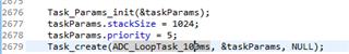
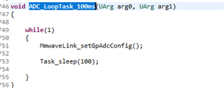
void ADC_LoopTask_100ms(UArg arg0, UArg arg1);
/* external sleep function when in idle (used in .cfg file) */
void MmwDemo_sleep(void);
/* DSS to MSS exception signalling ISR */
static void MmwDemo_installDss2MssExceptionSignallingISR(void);
/**************************************************************************
************************* Millimeter Wave Demo Functions **********************
**************************************************************************/
/**
* @b Description
* @n
* Registered event function which is invoked when an event from the
* BSS is received.
*
* @param[in] msgId
* Message Identifier
* @param[in] sbId
* Subblock identifier
* @param[in] sbLen
* Length of the subblock
* @param[in] payload
* Pointer to the payload buffer
*
* @retval
* Always returns 0 [Continue passing the event to the peer domain]
*/
int32_t MmwDemo_mssMmwaveEventCallbackFxn(uint16_t msgId, uint16_t sbId, uint16_t sbLen, uint8_t *payload)
{
uint16_t asyncSB = RL_GET_SBID_FROM_UNIQ_SBID(sbId);
#if 0
System_printf ("Debug: BSS Event MsgId: %d [Sub Block Id: %d Sub Block Length: %d]\n",
msgId, sbId, sbLen);
#endif
/* Process the received message: */
switch (msgId)
{
case RL_RF_ASYNC_EVENT_MSG:
{
/* Received Asychronous Message: */
switch (asyncSB)
{
case RL_RF_AE_CPUFAULT_SB:
{
/* Post event to datapath task notify BSS events */
Event_post(gMmwMssMCB.eventHandle, MMWDEMO_BSS_CPUFAULT_EVT);
break;
}
case RL_RF_AE_ESMFAULT_SB:
{
/* Post event to datapath task notify BSS events */
Event_post(gMmwMssMCB.eventHandle, MMWDEMO_BSS_ESMFAULT_EVT);
break;
}
case RL_RF_AE_ANALOG_FAULT_SB:
{
/* Post event to datapath task notify BSS events */
Event_post(gMmwMssMCB.eventHandle, MMWDEMO_BSS_ANALOGFAULT_EVT);
break;
}
case RL_RF_AE_INITCALIBSTATUS_SB:
{
rlRfInitComplete_t* ptrRFInitCompleteMessage;
uint32_t calibrationStatus;
/* Get the RF-Init completion message: */
ptrRFInitCompleteMessage = (rlRfInitComplete_t*)payload;
calibrationStatus = ptrRFInitCompleteMessage->calibStatus & 0xFFFU;
/* Display the calibration status: */
CLI_write ("Debug: Init Calibration Status = 0x%x\n", calibrationStatus);
break;
}
case RL_RF_AE_FRAME_TRIGGER_RDY_SB:
{
/* This event is not handled on MSS */
break;
}
case RL_RF_AE_MON_TIMING_FAIL_REPORT_SB:
{
/* Increment the statistics for the number of failed reports */
gMmwMssMCB.stats.numFailedTimingReports++;
#if 0
/* if something needs to be done then need to implement the function
to handle the event below in MmwDemo_mssCtrlPathTask()*/
/* Post event to datapath task notify BSS events */
Event_post(gMmwMssMCB.eventHandle, MMWDEMO_BSS_MONITORING_REP_EVT);
#endif
break;
}
case RL_RF_AE_RUN_TIME_CALIB_REPORT_SB:
{
/* Increment the statistics for the number of received calibration reports */
gMmwMssMCB.stats.numCalibrationReports++;
#if 0
/* if something needs to be done then need to implement the function
to handle the event below in MmwDemo_mssCtrlPathTask()*/
/* Post event to datapath task notify BSS events */
Event_post(gMmwMssMCB.eventHandle, MMWDEMO_BSS_CALIBRATION_REP_EVT);
#endif
break;
}
case RL_RF_AE_FRAME_END_SB:
{
/*Received Frame Stop async event from BSS.
No further action required on MSS as it will
wait for a message from DSS when it is done (MMWDEMO_DSS2MSS_STOPDONE)*/
break;
}
case RL_RF_AE_GPADC_MEAS_DATA_SB:
{
isGetGpAdcMeasData = 1U;
memcpy(&rcvGpAdcData, payload, sizeof(rlRecvdGpAdcData_t));
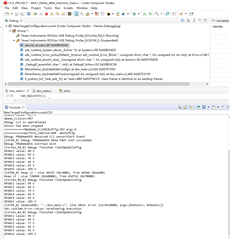
System_printf ("GPADC1 value: %d V\n", rcvGpAdcData.sensor[0].avg);
System_printf ("GPADC2 value: %d V\n", rcvGpAdcData.sensor[1].avg);
System_printf ("GPADC3 value: %d V\n", rcvGpAdcData.sensor[2].avg);
System_printf ("GPADC4 value: %d V\n", rcvGpAdcData.sensor[3].avg);
System_printf ("GPADC5 value: %d V\n", rcvGpAdcData.sensor[4].avg);
System_printf ("GPADC6 value: %d V\n", rcvGpAdcData.sensor[5].avg);
break;
}
default:
{
System_printf ("Error: Asynchronous Event SB Id %d not handled\n", asyncSB);
break;
}
}
break;
}
default:
{
System_printf ("Error: Asynchronous message %d is NOT handled\n", msgId);
break;
}
}
return 0;
}
/**
* @b Description
* @n
* Application registered callback function which is invoked after the configuration
* has been used to configure the mmWave link and the BSS. This is applicable only for
* the XWR16xx. The BSS can be configured only by the MSS *or* DSS. The callback API is
* triggered on the remote execution domain (which did not configure the BSS)
*
* @param[in] ptrCtrlCfg
* Pointer to the control configuration
*
* @retval
* Not applicable
*/
void MmwDemo_mssMmwaveConfigCallbackFxn(MMWave_CtrlCfg* ptrCtrlCfg)
{
/* For mmw Demo, mmwave_config() will always be called from MSS,
due to the fact CLI is running on MSS, hence this callback won't be called */
gMmwMssMCB.stats.datapathConfigEvt ++;
}
/**
* @b Description
* @n
* Application registered callback function which is invoked the mmWave link on BSS
* has been opened.
*
* @param[in] ptrOpenCfg
* Pointer to the open configuration
*
* @retval
* Not applicable
*/
static void MmwDemo_mssMmwaveOpenCallbackFxn(MMWave_OpenCfg* ptrOpenCfg)
{
return;
}
/**
* @b Description
* @n
* Application registered callback function which is invoked the mmWave link on BSS
* has been closed.
*
* @retval
* Not applicable
*/
static void MmwDemo_mssMmwaveCloseCallbackFxn(void)
{
return;
}
/**
* @b Description
* @n
* Application registered callback function which is invoked the mmWave link on BSS
* has been started. This is applicable only for the XWR16xx. The BSS can be configured
* only by the MSS *or* DSS. The callback API is triggered on the remote execution
* domain (which did not configure the BSS)
*
* @param[in] ptrCalibrationCfg
* Pointer to the calibration configuration
*
* @retval
* Not applicable
*/
void MmwDemo_mssMmwaveStartCallbackFxn(MMWave_CalibrationCfg* ptrCalibrationCfg)
{
/* Post an event to main data path task.
This function in only called when mmwave_start() is called on DSS */
gMmwMssMCB.stats.datapathStartEvt ++;
/* Post event to start is done */
Event_post(gMmwMssMCB.eventHandleNotify, MMWDEMO_DSS_START_COMPLETED_EVT);
}
/**
* @b Description
* @n
* Application registered callback function which is invoked the mmWave link on BSS
* has been stopped. This is applicable only for the XWR16xx. The BSS can be configured
* only by the MSS *or* DSS. The callback API is triggered on the remote execution
* domain (which did not configure the BSS)
*
* @retval
* Not applicable
*/
void MmwDemo_mssMmwaveStopCallbackFxn(void)
{
/* Possible sceanarios:
1. CLI sensorStop command triggers mmwave_stop() to be called from MSS
2. In case of Error, mmwave_stop() will be triggered either from MSS or DSS
*/
gMmwMssMCB.stats.datapathStopEvt ++;
}
/**
* @b Description
* @n
* Function to send a message to peer through Mailbox virtural channel
*
* @param[in] message
* Pointer to the MMW demo message.
*
* @retval
* Success - 0
* Fail < -1
*/
int32_t MmwDemo_mboxWrite(MmwDemo_message * message)
{
int32_t retVal = -1;
retVal = Mailbox_write (gMmwMssMCB.peerMailbox, (uint8_t*)message, sizeof(MmwDemo_message));
if (retVal == sizeof(MmwDemo_message))
{
retVal = 0;
}
return retVal;
}
/**
* @b Description
* @n
* The Task is used to handle the mmw demo messages received from
* Mailbox virtual channel.
*
* @param[in] arg0
* arg0 of the Task. Not used
* @param[in] arg1
* arg1 of the Task. Not used
*
* @retval
* Not Applicable.
*/
static void MmwDemo_mboxReadTask(UArg arg0, UArg arg1)
{
MmwDemo_message message;
int32_t retVal = 0;
uint32_t totalPacketLen;
uint32_t numPaddingBytes;
uint32_t itemIdx;
/* wait for new message and process all the messages received from the peer */
while(1)
{
Semaphore_pend(gMmwMssMCB.mboxSemHandle, BIOS_WAIT_FOREVER);
/* Read the message from the peer mailbox: We are not trying to protect the read
* from the peer mailbox because this is only being invoked from a single thread */
retVal = Mailbox_read(gMmwMssMCB.peerMailbox, (uint8_t*)&message, sizeof(MmwDemo_message));
if (retVal < 0)
{
/* Error: Unable to read the message. Setup the error code and return values */
System_printf ("Error: Mailbox read failed [Error code %d]\n", retVal);
}
else if (retVal == 0)
{
/* We are done: There are no messages available from the peer execution domain. */
continue;
}
else
{
/* Flush out the contents of the mailbox to indicate that we are done with the message. This will
* allow us to receive another message in the mailbox while we process the received message. */
Mailbox_readFlush (gMmwMssMCB.peerMailbox);
/* Process the received message: */
switch (message.type)
{
case MMWDEMO_DSS2MSS_DETOBJ_READY:
/* Got detetced objectes , shipped out through UART */
/* Send header */
totalPacketLen = sizeof(MmwDemo_output_message_header);
UART_writePolling (gMmwMssMCB.loggingUartHandle,
(uint8_t*)&message.body.detObj.header,
sizeof(MmwDemo_output_message_header));
/* Send TLVs */
for (itemIdx = 0; itemIdx < message.body.detObj.header.numTLVs; itemIdx++)
{
UART_writePolling (gMmwMssMCB.loggingUartHandle,
(uint8_t*)&message.body.detObj.tlv[itemIdx],
sizeof(MmwDemo_output_message_tl));
UART_writePolling (gMmwMssMCB.loggingUartHandle,
(uint8_t*)SOC_translateAddress(message.body.detObj.tlv[itemIdx].address,
SOC_TranslateAddr_Dir_FROM_OTHER_CPU,NULL),
message.body.detObj.tlv[itemIdx].length);
totalPacketLen += sizeof(MmwDemo_output_message_tl) + message.body.detObj.tlv[itemIdx].length;
}
/* Send padding to make total packet length multiple of MMWDEMO_OUTPUT_MSG_SEGMENT_LEN */
numPaddingBytes = MMWDEMO_OUTPUT_MSG_SEGMENT_LEN - (totalPacketLen & (MMWDEMO_OUTPUT_MSG_SEGMENT_LEN-1));
if (numPaddingBytes<MMWDEMO_OUTPUT_MSG_SEGMENT_LEN)
{
uint8_t padding[MMWDEMO_OUTPUT_MSG_SEGMENT_LEN];
/*DEBUG:*/ memset(&padding, 0xf, MMWDEMO_OUTPUT_MSG_SEGMENT_LEN);
UART_writePolling (gMmwMssMCB.loggingUartHandle,
padding,
numPaddingBytes);
}
/* Send a message to MSS to log the output data */
memset((void *)&message, 0, sizeof(MmwDemo_message));
message.type = MMWDEMO_MSS2DSS_DETOBJ_SHIPPED;
if (MmwDemo_mboxWrite(&message) != 0)
{
System_printf ("Error: Mailbox send message id=%d failed \n", message.type);
}
break;
case MMWDEMO_DSS2MSS_STOPDONE:
/* Post event that stop is done */
gMmwMssMCB.stats.dssSensorStop++;
Event_post(gMmwMssMCB.eventHandleNotify, MMWDEMO_DSS_STOP_COMPLETED_EVT);
break;
case MMWDEMO_DSS2MSS_ASSERT_INFO:
/* Send the received DSS assert info through CLI */
CLI_write ("DSS Exception: %s, line %d.\n", message.body.assertInfo.file,
message.body.assertInfo.line);
break;
case MMWDEMO_DSS2MSS_ISR_INFO_ADDRESS:
gMmwMssMCB.dss2mssIsrInfoAddress =
SOC_translateAddress(message.body.dss2mssISRinfoAddress,
SOC_TranslateAddr_Dir_FROM_OTHER_CPU, NULL);
MmwDemo_installDss2MssExceptionSignallingISR();
break;
default:
{
/* Message not support */
System_printf ("Error: unsupport Mailbox message id=%d\n", message.type);
break;
}
}
}
}
}
/**
* @b Description
* @n
* This function is a callback funciton that invoked when a message is received from the peer.
*
* @param[in] handle
* Handle to the Mailbox on which data was received
* @param[in] peer
* Peer from which data was received
* @retval
* Not Applicable.
*/
void MmwDemo_mboxCallback
(
Mbox_Handle handle,
Mailbox_Type peer
)
{
/* Message has been received from the peer endpoint. Wakeup the mmWave thread to process
* the received message. */
Semaphore_post (gMmwMssMCB.mboxSemHandle);
}
#if 0 //OD DEMO: Remove unused functions
/**
* @b Description
* @n
* Function that configures the BPM chirps based on the stored BPM CLI commands.
* The MMW demo supports only a fixed BPM scheme and this scheme is implemented
* by this function.
*
* @retval
* 0 - Success.
* <0 - Failed with errors
*/
int32_t MmwDemo_bpmConfig(void)
{
uint8_t subframe;
uint8_t numberOfSubframes = 1;
int32_t errCode;
rlBpmChirpCfg_t bpmChirpCfg;
MMWave_BpmChirpHandle bpmChirpHandle;
if(gMmwMssMCB.cfg.ctrlCfg.dfeDataOutputMode == MMWave_DFEDataOutputMode_ADVANCED_FRAME)
{
/* BPM configuration for all valid subframes */
numberOfSubframes = gMmwMssMCB.cfg.ctrlCfg.u.advancedFrameCfg.frameCfg.frameSeq.numOfSubFrames;
}
for(subframe = 0; subframe < numberOfSubframes; subframe++)
{
/* Is BPM enabled*/
if(gMmwMssMCB.cliCfg[subframe].bpmCfg.isEnabled)
{
/*configure chirp 0 (++)*/
memset ((void *)&bpmChirpCfg, 0, sizeof(rlBpmChirpCfg_t));
bpmChirpCfg.chirpStartIdx = gMmwMssMCB.cliCfg[subframe].bpmCfg.chirp0Idx;
bpmChirpCfg.chirpEndIdx = gMmwMssMCB.cliCfg[subframe].bpmCfg.chirp0Idx;
/* Phase configuration: TX0 positive, TX1 positive*/
bpmChirpCfg.constBpmVal = 0U;
bpmChirpHandle = MMWave_addBpmChirp (gMmwMssMCB.ctrlHandle, &bpmChirpCfg, &errCode);
if (bpmChirpHandle == NULL)
{
System_printf ("Error: Unable to add BPM cfg chirp 0. Subframe %d [Error code %d]\n",subframe, errCode);
return -1;
}
/*configure chirp 1 (++)*/
memset ((void *)&bpmChirpCfg, 0, sizeof(rlBpmChirpCfg_t));
bpmChirpCfg.chirpStartIdx = gMmwMssMCB.cliCfg[subframe].bpmCfg.chirp1Idx;
bpmChirpCfg.chirpEndIdx = gMmwMssMCB.cliCfg[subframe].bpmCfg.chirp1Idx;
/* Phase configuration: TX0 positive, TX1 negative*/
bpmChirpCfg.constBpmVal = 0xCU;
bpmChirpHandle = MMWave_addBpmChirp (gMmwMssMCB.ctrlHandle, &bpmChirpCfg, &errCode);
if (bpmChirpHandle == NULL)
{
System_printf ("Error: Unable to add BPM cfg chirp 1. Subframe %d [Error code %d]\n",subframe, errCode);
return -1;
}
}
else
{
/*BPM is disabled.
Configure the range of chirps [chirp0Idx..chirp1Idx]
all to have zero phase.*/
memset ((void *)&bpmChirpCfg, 0, sizeof(rlBpmChirpCfg_t));
bpmChirpCfg.chirpStartIdx = gMmwMssMCB.cliCfg[subframe].bpmCfg.chirp0Idx;
bpmChirpCfg.chirpEndIdx = gMmwMssMCB.cliCfg[subframe].bpmCfg.chirp1Idx;
/* Phase configuration: TX0 positive, TX1 positive*/
bpmChirpCfg.constBpmVal = 0U;
bpmChirpHandle = MMWave_addBpmChirp (gMmwMssMCB.ctrlHandle, &bpmChirpCfg, &errCode);
if (bpmChirpHandle == NULL)
{
System_printf ("Error: Unable to add BPM cfg for BPM disabled. Subframe %d [Error code %d]\n",subframe, errCode);
return -1;
}
}
}
return 0;
}
#endif
/**
* @b Description
* @n
* Function to Setup the HSI Clock. Required for LVDS streaming.
*
* @retval
* 0 - Success.
* <0 - Failed with errors
*/
int32_t MmwDemo_mssSetHsiClk(void)
{
rlDevHsiClk_t hsiClkgs;
int32_t retVal;
/*************************************************************************************
* Setup the HSI Clock through the mmWave Link:
*************************************************************************************/
memset ((void*)&hsiClkgs, 0, sizeof(rlDevHsiClk_t));
/* Setup the HSI Clock as per the Radar Interface Document:
* - This is set to 600Mhz DDR Mode */
hsiClkgs.hsiClk = 0x9;
/* Setup the HSI in the radar link: */
retVal = rlDeviceSetHsiClk(RL_DEVICE_MAP_CASCADED_1, &hsiClkgs);
if (retVal != RL_RET_CODE_OK)
{
/* Error: Unable to set the HSI clock */
System_printf ("Error: Setting up the HSI Clock Failed [Error %d]\n", retVal);
return -1;
}
/*The delay below is needed only if the DCA1000EVM is being used to capture the data traces.
This is needed because the DCA1000EVM FPGA needs the delay to lock to the
bit clock before they can start capturing the data correctly. */
Task_sleep(HSI_DCA_MIN_DELAY_MSEC);
return 0;
}
/**
* @b Description
* @n
* Function to do Data Path Configuration on MSS. After received Configuration from
* CLI, this function will start the system configuration process, inclucing mmwaveLink, BSS
* and DSS.
*
* @retval
* 0 - Success.
* <0 - Failed with errors
*/
int32_t MmwDemo_mssDataPathConfig(void)
{
int32_t errCode;
/* Has the mmWave module been opened? */
if (gMmwMssMCB.isMMWaveOpen == false)
{
/* Get the open configuration from the CLI mmWave Extension */
CLI_getMMWaveExtensionOpenConfig (&gMmwMssMCB.cfg.openCfg);
/* NO: Setup the calibration frequency: */
#ifndef SOC_XWR68XX
gMmwMssMCB.cfg.openCfg.freqLimitLow = 760U;
gMmwMssMCB.cfg.openCfg.freqLimitHigh = 810U;
#else
gMmwMssMCB.cfg.openCfg.freqLimitLow = 600U;
gMmwMssMCB.cfg.openCfg.freqLimitHigh = 640U;
#endif
/* Disable the frame start async event so that small chirp times
are supported. If this event is enabled it will break real-time
for small chirp times and cause 1D processing to crash
due to lack of MIPS*/
gMmwMssMCB.cfg.openCfg.disableFrameStartAsyncEvent = true;
gMmwMssMCB.cfg.openCfg.disableFrameStopAsyncEvent = false;
/* No custom calibration: */
gMmwMssMCB.cfg.openCfg.useCustomCalibration = false;
gMmwMssMCB.cfg.openCfg.customCalibrationEnableMask = 0x0;
/* Set calibration time unit to 1 frame duration as the demo
doesn't support any monitoring related functionality. */
gMmwMssMCB.cfg.openCfg.calibMonTimeUnit = 1;
/* Open the mmWave module: */
if (MMWave_open (gMmwMssMCB.ctrlHandle, &gMmwMssMCB.cfg.openCfg, NULL, &errCode) < 0)
{
System_printf ("Error: MMWDemoMSS mmWave open configuration failed [Error code %d]\n", errCode);
return -1;
}
#ifdef SOC_XWR68XX
{
rlDynPwrSave_t psdata;
psdata.blkCfg = 7; //enable Tx, Rx, Lo Dist
psdata.reserved = 0;
errCode = rlRfDynamicPowerSave(RL_DEVICE_MAP_INTERNAL_BSS, &psdata);
if (errCode != RL_RET_CODE_OK)
{
/* Error: Unable to set the power saving mode */
System_printf ("Error: rlRfDynamicPowerSave config failed [Error code %d]\n", errCode);
return -1;
}
}
#endif
/* mmWave module has been opened. */
gMmwMssMCB.isMMWaveOpen = true;
/*Set up HSI clock*/
if(MmwDemo_mssSetHsiClk() < 0)
{
System_printf ("Error: MmwDemo_mssSetHsiClk failed.\n");
return -1;
}
}
else
{
/* openCfg related configurations like chCfg, lowPowerMode, adcCfg
* are only used on the first sensor start. If they are different
* on a subsequent sensor start, then generate a fatal error
* so the user does not think that the new (changed) configuration
* takes effect, the board needs to be reboot for the new
* configuration to be applied.
*/
MMWave_OpenCfg openCfg;
CLI_getMMWaveExtensionOpenConfig (&openCfg);
/* Initialize to same as in "if" part where open is done
* to allow memory compare of structures to be used.
* Note that even if structures may have holes, the memory
* compare is o.k because CLI always stores the configurations
* in the same global CLI structure which is copied over to the
* one supplied by the application through the
* CLI_getMMWaveExtensionOpenConfig API. Not using memcmp will
* require individual field comparisons which is probably
* more code size and cumbersome.
*/
openCfg.freqLimitLow = 760U;
openCfg.freqLimitHigh = 810U;
openCfg.disableFrameStartAsyncEvent = true;
openCfg.disableFrameStopAsyncEvent = false;
/* Compare openCfg */
if(memcmp((void *)&gMmwMssMCB.cfg.openCfg, (void *)&openCfg,
sizeof(MMWave_OpenCfg)) != 0)
{
/* Post event to CLI task that start failed so that CLI/GUI can be notified */
Event_post(gMmwMssMCB.eventHandleNotify, MMWDEMO_DSS_START_FAILED_EVT);
MmwDemo_mssAssert(0);
}
}
/* Get the control configuration from the CLI mmWave Extension */
CLI_getMMWaveExtensionConfig (&gMmwMssMCB.cfg.ctrlCfg);
#if 0 //OD DEMO: Remove unused messages
/* Prepare BPM configuration */
if(MmwDemo_bpmConfig() < 0)
{
System_printf ("Error: MMWDemoMSS mmWave BPM Configuration failed\n");
return -1;
}
#endif
/* Configure the mmWave module: */
if (MMWave_config (gMmwMssMCB.ctrlHandle, &gMmwMssMCB.cfg.ctrlCfg, &errCode) < 0)
{
System_printf ("Error: MMWDemoMSS mmWave Configuration failed [Error code %d]\n", errCode);
return -1;
}
return 0;
}
/**
* @b Description
* @n
* Function to do Data Path Start on MSS. After received SensorStart command, MSS will
* start all data path componets including mmwaveLink, BSS and DSS.
*
* @retval
* 0 - Success.
* <0 - Failed with errors
*/
int32_t MmwDemo_mssDataPathStart(void)
{
int32_t errCode;
MMWave_CalibrationCfg calibrationCfg;
/* Initialize the calibration configuration: */
memset ((void*)&calibrationCfg, 0, sizeof(MMWave_CalibrationCfg));
/* Populate the calibration configuration: */
calibrationCfg.dfeDataOutputMode =
gMmwMssMCB.cfg.ctrlCfg.dfeDataOutputMode;
calibrationCfg.u.chirpCalibrationCfg.enableCalibration = true;
calibrationCfg.u.chirpCalibrationCfg.enablePeriodicity = true;
calibrationCfg.u.chirpCalibrationCfg.periodicTimeInFrames = 10U;
/* Start the mmWave module: The configuration has been applied successfully. */
if (MMWave_start (gMmwMssMCB.ctrlHandle, &calibrationCfg, &errCode) < 0)
{
/* Error: Unable to start the mmWave control */
System_printf ("Error: MMWDemoMSS mmWave Start failed [Error code %d]\n", errCode);
return -1;
}
System_printf ("Debug: MMWDemoMSS mmWave Start succeeded \n");
return 0;
}
/**
* @b Description
* @n
* Function to do Data Path Start on MSS. After received SensorStart command, MSS will
* start all data path componets including mmwaveLink, BSS and DSS.
*
* @retval
* 0 - Success.
* <0 - Failed with errors
*/
int32_t MmwDemo_mssDataPathStop(void)
{
int32_t errCode;
MMWave_ErrorLevel errorLevel;
int16_t mmWaveErrorCode;
int16_t subsysErrorCode;
int32_t retVal = 0;
/* Start the mmWave module: The configuration has been applied successfully. */
if (MMWave_stop (gMmwMssMCB.ctrlHandle, &errCode) < 0)
{
/* Error/Warning: Unable to stop the mmWave module */
MMWave_decodeError (errCode, &errorLevel, &mmWaveErrorCode, &subsysErrorCode);
if (errorLevel == MMWave_ErrorLevel_ERROR)
{
/* Error: Set the return value to indicate error: */
System_printf ("Error: MMWDemoMSS mmWave Stop failed [mmWave Error: %d Subsys: %d]\n", mmWaveErrorCode, subsysErrorCode);
retVal = -1;
}
else
{
System_printf ("Warning: MMWDemoMSS mmWave Stop failed [mmWave Error: %d Subsys: %d]\n", mmWaveErrorCode, subsysErrorCode);
/* Warning: This is treated as a successful stop. */
}
}
return retVal;
}
/**
* @b Description
* @n
* The task is used to provide an execution context for the mmWave
* control task
*
* @retval
* Not Applicable.
*/
void MmwDemo_mmWaveCtrlTask(UArg arg0, UArg arg1)
{
int32_t errCode;
while (1)
{
/* Execute the mmWave control module: */
if (MMWave_execute (gMmwMssMCB.ctrlHandle, &errCode) < 0)
System_printf ("Error: mmWave control execution failed [Error code %d]\n", errCode);
}
}
/**
* @b Description
* @n
* This is a utility function which can be invoked from the CLI or
* the Switch press to start the sensor. This sends an event to the
* sensor management task where the actual *start* procedure is
* implemented.
*
* @retval
* Not applicable
*/
void MmwDemo_notifySensorStart(bool doReconfig)
{
gMmwMssMCB.stats.cliSensorStartEvt ++;
if (doReconfig) {
/* Post sensorStart event to start reconfig and then start the sensor */
Event_post(gMmwMssMCB.eventHandle, MMWDEMO_CLI_SENSORSTART_EVT);
}
else
{
/* Post frameStart event to skip reconfig and just start the sensor */
Event_post(gMmwMssMCB.eventHandle, MMWDEMO_CLI_FRAMESTART_EVT);
}
}
/**
* @b Description
* @n
* This is a utility function which can be invoked from the CLI or
* the Switch press to start the sensor. This sends an event to the
* sensor management task where the actual *start* procedure is
* implemented.
*
* @retval
* Not applicable
*/
void MmwDemo_notifySensorStop(void)
{
gMmwMssMCB.stats.cliSensorStopEvt ++;
/* Post sensorSTOP event to notify sensor stop command */
Event_post(gMmwMssMCB.eventHandle, MMWDEMO_CLI_SENSORSTOP_EVT);
}
/**
* @b Description
* @n
* This is a utility function which can be used by the CLI to
* pend for start complete (after MmwDemo_notifySensorStart is called)
*
* @retval
* Not applicable
*/
int32_t MmwDemo_waitSensorStartComplete(void)
{
UInt event;
int32_t retVal;
/* Pend on the START NOTIFY event */
event = Event_pend(gMmwMssMCB.eventHandleNotify,
Event_Id_NONE,
MMWDEMO_DSS_START_COMPLETED_EVT | MMWDEMO_DSS_START_FAILED_EVT,
BIOS_WAIT_FOREVER);
/************************************************************************
* DSS event:: START notification
************************************************************************/
if(event & MMWDEMO_DSS_START_COMPLETED_EVT)
{
/* Sensor has been started successfully */
gMmwMssMCB.isSensorStarted = true;
/* Turn on the LED */
#ifdef SOC_XWR16XX
GPIO_write (SOC_XWR16XX_GPIO_2, 1U);
#endif
#ifdef SOC_XWR18XX
GPIO_write (SOC_XWR18XX_GPIO_2, 1U);
#endif
#ifdef SOC_XWR68XX
//GPIO_write (SOC_XWR68XX_GPIO_2, 1U);
#endif
retVal = 0;
}
else if(event & MMWDEMO_DSS_START_FAILED_EVT)
{
/* Sensor start failed */
gMmwMssMCB.isSensorStarted = false;
retVal = -1;
}
else
{
/* we should block forever till we get the events. If the desired event
didnt happen, then throw an assert */
retVal = -1;
MmwDemo_mssAssert(0);
}
return retVal;
}
/**
* @b Description
* @n
* This is a utility function which can be used by the CLI to
* pend for stop complete (after MmwDemo_notifySensorStart is called)
*
* @retval
* Not applicable
*/
void MmwDemo_waitSensorStopComplete(void)
{
UInt event;
/* Pend on the START NOTIFY event */
event = Event_pend(gMmwMssMCB.eventHandleNotify,
MMWDEMO_DSS_STOP_COMPLETED_EVT | MMWDEMO_MSS_STOP_COMPLETED_EVT, /* andMask */
Event_Id_NONE, /* orMask */
BIOS_WAIT_FOREVER);
/************************************************************************
* DSS event:: STOP notification
************************************************************************/
if(event & (MMWDEMO_DSS_STOP_COMPLETED_EVT | MMWDEMO_MSS_STOP_COMPLETED_EVT))
{
/* Sensor has been stopped successfully */
gMmwMssMCB.isSensorStarted = false;
/* Turn on the LED */
#ifdef SOC_XWR16XX
GPIO_write (SOC_XWR16XX_GPIO_2, 0U);
#endif
#ifdef SOC_XWR18XX
GPIO_write (SOC_XWR18XX_GPIO_2, 0U);
#endif
#ifdef SOC_XWR68XX
//GPIO_write (SOC_XWR68XX_GPIO_2, 0U);
#endif
/* print for user */
System_printf("Sensor has been stopped\n");
}
else {
/* we should block forever till we get the event. If the desired event
didnt happen, then throw an assert */
MmwDemo_mssAssert(0);
}
}
/**
* @b Description
* @n
* Callback function invoked when the GPIO switch is pressed.
* This is invoked from interrupt context.
*
* @param[in] index
* GPIO index configured as input
*
* @retval
* Not applicable
*/
static void MmwDemo_switchPressFxn(unsigned int index)
{
/* Post semaphore to process GPIO switch event */
Semaphore_post (gMmwMssMCB.gpioSemHandle);
}
/**
* @b Description
* @n
* The task is used to process data path events
* control task
*
* @retval
* Not Applicable.
*/
void MmwDemo_mssCtrlPathTask(UArg arg0, UArg arg1)
{
UInt event;
#if 0 /* no gpio on our board */
/**********************************************************************
* Setup the PINMUX:
* - GPIO Input : Configure pin J13 as GPIO_1 input
* - GPIO Output: Configure pin K13 as GPIO_2 output
**********************************************************************/
#ifdef SOC_XWR68XX
Pinmux_Set_OverrideCtrl(SOC_XWR68XX_PINJ13_PADAC, PINMUX_OUTEN_RETAIN_HW_CTRL, PINMUX_INPEN_RETAIN_HW_CTRL);
Pinmux_Set_FuncSel(SOC_XWR68XX_PINJ13_PADAC, SOC_XWR68XX_PINJ13_PADAC_GPIO_1);
Pinmux_Set_OverrideCtrl(SOC_XWR68XX_PINK13_PADAZ, PINMUX_OUTEN_RETAIN_HW_CTRL, PINMUX_INPEN_RETAIN_HW_CTRL);
Pinmux_Set_FuncSel(SOC_XWR68XX_PINK13_PADAZ, SOC_XWR68XX_PINK13_PADAZ_GPIO_2);
#endif
/**********************************************************************
* Setup the SW1 switch on the EVM connected to GPIO_1
* - This is used as an input
* - Enable interrupt to be notified on a switch press
**********************************************************************/
#ifdef SOC_XWR68XX
GPIO_setConfig (SOC_XWR68XX_GPIO_1, GPIO_CFG_INPUT | GPIO_CFG_IN_INT_RISING | GPIO_CFG_IN_INT_LOW);
GPIO_setCallback (SOC_XWR68XX_GPIO_1, MmwDemo_switchPressFxn);
GPIO_enableInt (SOC_XWR68XX_GPIO_1);
#endif
/**********************************************************************
* Setup the DS3 LED on the EVM connected to GPIO_2
**********************************************************************/
#ifdef SOC_XWR68XX
GPIO_setConfig (SOC_XWR68XX_GPIO_2, GPIO_CFG_OUTPUT);
#endif
#endif
/* Data Path management task Main loop */
while (1)
{
event = Event_pend(gMmwMssMCB.eventHandle,
Event_Id_NONE,
MMWDEMO_CLI_EVENTS | MMWDEMO_BSS_FAULT_EVENTS |
MMWDEMO_DSS_EXCEPTION_EVENTS,
BIOS_WAIT_FOREVER);
/************************************************************************
* CLI event:: SensorStart
************************************************************************/
if(event & MMWDEMO_CLI_SENSORSTART_EVT)
{
System_printf ("Debug: MMWDemoMSS Received CLI sensorStart Event\n");
/* Setup the data path: */
if(gMmwMssMCB.isSensorStarted==false)
{
if (MmwDemo_mssDataPathConfig () < 0) {
/* Post start failed event; error printing is done in function above */
Event_post(gMmwMssMCB.eventHandleNotify, MMWDEMO_DSS_START_FAILED_EVT);
continue;
}
else
{
/* start complete event is posted via DSS */
}
}
else
{
/* Post start complete event as this is just a duplicate command */
Event_post(gMmwMssMCB.eventHandleNotify, MMWDEMO_DSS_START_COMPLETED_EVT);
continue;
}
}
/************************************************************************
* CLI event:: SensorStop
************************************************************************/
if(event & MMWDEMO_CLI_SENSORSTOP_EVT)
{
if(gMmwMssMCB.isSensorStarted==true)
{
if (MmwDemo_mssDataPathStop () < 0) {
/* Do we need stop fail event? */
DebugP_assert(0);
}
else
{
/* DSS will post the stop completed event */
}
}
else
{
/* Post data path stop complete event on behalf on Datapath in case sensor is already in stop state */
Event_post(gMmwMssMCB.eventHandleNotify, MMWDEMO_DSS_STOP_COMPLETED_EVT);
}
/* In all cases send MSS stop complete */
Event_post(gMmwMssMCB.eventHandleNotify, MMWDEMO_MSS_STOP_COMPLETED_EVT);
}
/************************************************************************
* CLI event:: Framestart
************************************************************************/
if(event & MMWDEMO_CLI_FRAMESTART_EVT)
{
/* error printing happens inside this function */
if(gMmwMssMCB.isSensorStarted==false)
{
if (MmwDemo_mssDataPathStart () < 0) {
/* Post start failed event; error printing is done in function above */
Event_post(gMmwMssMCB.eventHandleNotify, MMWDEMO_DSS_START_FAILED_EVT);
continue;
}
}
/* Post event to start is done */
Event_post(gMmwMssMCB.eventHandleNotify, MMWDEMO_DSS_START_COMPLETED_EVT);
}
/************************************************************************
* BSS event:: CPU fault
************************************************************************/
if(event & MMWDEMO_BSS_CPUFAULT_EVT)
{
MmwDemo_mssAssert(0);
break;
}
/************************************************************************
* BSS event:: ESM fault
************************************************************************/
if(event & MMWDEMO_BSS_ESMFAULT_EVT)
{
MmwDemo_mssAssert(0);
break;
}
/************************************************************************
* BSS event:: Analog fault
************************************************************************/
if (event & MMWDEMO_BSS_ANALOGFAULT_EVT)
{
MmwDemo_mssAssert(0);
break;
}
if(event & MMWDEMO_DSS_CHIRP_PROC_DEADLINE_MISS_EVT)
{
CLI_write ("DSS Chirp Processing Deadline Miss Exception.\n");
DebugP_assert(0);
break;
}
if(event & MMWDEMO_DSS_FRAME_PROC_DEADLINE_MISS_EVT)
{
CLI_write ("DSS Frame Processing Deadline Miss Exception.\n");
DebugP_assert(0);
break;
}
}
System_printf("Debug: MMWDemoDSS Data path exit\n");
}
/**
* @b Description
* @n
* The task is used to process events related
* to pressing the GPIO switch
*
* @retval
* Not Applicable.
*/
void MmwDemo_gpioSwitchTask(UArg arg0, UArg arg1)
{
/* wait for GPIO switch event */
while(1)
{
Semaphore_pend(gMmwMssMCB.gpioSemHandle, BIOS_WAIT_FOREVER);
/* Was the sensor started? */
if (gMmwMssMCB.isSensorStarted == true)
{
/* YES: We need to stop the sensor now */
MmwDemo_notifySensorStop();
/* Pend for completion */
MmwDemo_waitSensorStopComplete();
}
else
{
/* NO: We need to start the sensor now. */
MmwDemo_notifySensorStart(true);
/* Pend for completion */
if(MmwDemo_waitSensorStartComplete() == -1)
{
/* Sensor start failed */
MmwDemo_mssAssert(0);
}
}
}
}
int32_t MmwaveLink_setGpAdcConfig (void)
{
int32_t retVal;
retVal = rlSetGpAdcConfig(RL_DEVICE_MAP_INTERNAL_BSS, (rlGpAdcCfg_t*)&gpAdcCfg);
if(retVal != 0)
{
System_printf("Error: rlSetGpAdcConfig retVal=%d\n", retVal);
return -1;
}
System_printf("Debug: Finished rlSetGpAdcConfig\n");
while(isGetGpAdcMeasData == 0U)
{
Task_sleep(1);
}
return 0;
}
void ADC_LoopTask_100ms(UArg arg0, UArg arg1)
{
while(1)
{
MmwaveLink_setGpAdcConfig();
Task_sleep(100);
}
}
/**
* @b Description
* @n
* DSS to MSS ISR used for direct signalling of things like urgent exception
* events from DSS. Posts deadline miss events to @ref MmwDemo_mssCtrlPathTask.
*
* @retval
* Not Applicable.
*/
void MmwDemo_Dss2MssISR(uintptr_t arg)
{
switch(*(uint8_t*)gMmwMssMCB.dss2mssIsrInfoAddress)
{
case MMWDEMO_DSS2MSS_CHIRP_PROC_DEADLINE_MISS_EXCEPTION:
Event_post(gMmwMssMCB.eventHandle, MMWDEMO_DSS_CHIRP_PROC_DEADLINE_MISS_EVT);
break;
case MMWDEMO_DSS2MSS_FRAME_PROC_DEADLINE_MISS_EXCEPTION:
Event_post(gMmwMssMCB.eventHandle, MMWDEMO_DSS_FRAME_PROC_DEADLINE_MISS_EVT);
break;
default:
MmwDemo_mssAssert(0);
break;
}
}
/**
* @b Description
* @n
* Installs DSS to MSS Software Interrupt ISR for exception signalling.
*
* @retval
* Not Applicable.
*/
static void MmwDemo_installDss2MssExceptionSignallingISR(void)
{
HwiP_Params hwiParams;
volatile HwiP_Handle hwiHandle;
HwiP_Params_init(&hwiParams);
hwiParams.name = "Dss2MssSwISR";
hwiHandle = HwiP_create(MMWDEMO_DSS2MSS_EXCEPTION_SIGNALLING_SW_INT_MSS,
MmwDemo_Dss2MssISR, &hwiParams);
}
static void pin_config(void)
{
Pinmux_Set_OverrideCtrl(SOC_XWR68XX_PINE15_PADAG, PINMUX_OUTEN_RETAIN_HW_CTRL, PINMUX_INPEN_RETAIN_HW_CTRL);
Pinmux_Set_FuncSel(SOC_XWR68XX_PINE15_PADAG, SOC_XWR68XX_PINE15_PADAG_SPIA_CSN);
Pinmux_Set_OverrideCtrl(SOC_XWR68XX_PIND13_PADAD, PINMUX_OUTEN_RETAIN_HW_CTRL, PINMUX_INPEN_RETAIN_HW_CTRL);
Pinmux_Set_FuncSel(SOC_XWR68XX_PIND13_PADAD, SOC_XWR68XX_PIND13_PADAD_SPIA_MOSI);
Pinmux_Set_OverrideCtrl(SOC_XWR68XX_PINE14_PADAE, PINMUX_OUTEN_RETAIN_HW_CTRL, PINMUX_INPEN_RETAIN_HW_CTRL);
Pinmux_Set_FuncSel(SOC_XWR68XX_PINE14_PADAE, SOC_XWR68XX_PINE14_PADAE_SPIA_MISO);
Pinmux_Set_OverrideCtrl(SOC_XWR68XX_PINE13_PADAF, PINMUX_OUTEN_RETAIN_HW_CTRL, PINMUX_INPEN_RETAIN_HW_CTRL);
Pinmux_Set_FuncSel(SOC_XWR68XX_PINE13_PADAF, SOC_XWR68XX_PINE13_PADAF_SPIA_CLK);
Pinmux_Set_OverrideCtrl(SOC_XWR68XX_PINH14_PADAK, PINMUX_OUTEN_RETAIN_HW_CTRL, PINMUX_INPEN_RETAIN_HW_CTRL);
Pinmux_Set_FuncSel(SOC_XWR68XX_PINH14_PADAK, SOC_XWR68XX_PINH14_PADAK_SPIB_CSN);
Pinmux_Set_OverrideCtrl(SOC_XWR68XX_PINP13_PADAA, PINMUX_OUTEN_RETAIN_HW_CTRL, PINMUX_INPEN_RETAIN_HW_CTRL);
Pinmux_Set_FuncSel(SOC_XWR68XX_PINP13_PADAA, SOC_XWR68XX_PINP13_PADAA_SPIB_CSN1);
/* Setup the PINMUX to bring out the UART-3 */
Pinmux_Set_OverrideCtrl(SOC_XWR68XX_PINF14_PADAJ, PINMUX_OUTEN_RETAIN_HW_CTRL, PINMUX_INPEN_RETAIN_HW_CTRL);
Pinmux_Set_FuncSel(SOC_XWR68XX_PINF14_PADAJ, SOC_XWR68XX_PINF14_PADAJ_MSS_UARTB_TX);
Pinmux_Set_OverrideCtrl(SOC_XWR68XX_PING14_PADAI, PINMUX_OUTEN_RETAIN_HW_CTRL, PINMUX_INPEN_RETAIN_HW_CTRL);
Pinmux_Set_FuncSel(SOC_XWR68XX_PING14_PADAI, SOC_XWR68XX_PING14_PADAI_I2C_SCL);
Pinmux_Set_OverrideCtrl(SOC_XWR68XX_PINF13_PADAH, PINMUX_OUTEN_RETAIN_HW_CTRL, PINMUX_INPEN_RETAIN_HW_CTRL);
Pinmux_Set_FuncSel(SOC_XWR68XX_PINF13_PADAH, SOC_XWR68XX_PINF13_PADAH_I2C_SDA);
/**********************************************************************
* Setup the PINMUX:
* - for QSPI Flash
**********************************************************************/
Pinmux_Set_OverrideCtrl(SOC_XWR68XX_PINR12_PADAP, PINMUX_OUTEN_RETAIN_HW_CTRL, PINMUX_INPEN_RETAIN_HW_CTRL);
Pinmux_Set_FuncSel(SOC_XWR68XX_PINR12_PADAP, SOC_XWR68XX_PINR12_PADAP_QSPI_CLK);
Pinmux_Set_OverrideCtrl(SOC_XWR68XX_PINP11_PADAQ, PINMUX_OUTEN_RETAIN_HW_CTRL, PINMUX_INPEN_RETAIN_HW_CTRL);
Pinmux_Set_FuncSel(SOC_XWR68XX_PINP11_PADAQ, SOC_XWR68XX_PINP11_PADAQ_QSPI_CSN);
Pinmux_Set_OverrideCtrl(SOC_XWR68XX_PINR13_PADAL, PINMUX_OUTEN_RETAIN_HW_CTRL, PINMUX_INPEN_RETAIN_HW_CTRL);
Pinmux_Set_FuncSel(SOC_XWR68XX_PINR13_PADAL, SOC_XWR68XX_PINR13_PADAL_QSPI_D0);
Pinmux_Set_OverrideCtrl(SOC_XWR68XX_PINN12_PADAM, PINMUX_OUTEN_RETAIN_HW_CTRL, PINMUX_INPEN_RETAIN_HW_CTRL);
Pinmux_Set_FuncSel(SOC_XWR68XX_PINN12_PADAM, SOC_XWR68XX_PINN12_PADAM_QSPI_D1);
Pinmux_Set_OverrideCtrl(SOC_XWR68XX_PINR14_PADAN, PINMUX_OUTEN_RETAIN_HW_CTRL, PINMUX_INPEN_RETAIN_HW_CTRL);
Pinmux_Set_FuncSel(SOC_XWR68XX_PINR14_PADAN, SOC_XWR68XX_PINR14_PADAN_QSPI_D2);
Pinmux_Set_OverrideCtrl(SOC_XWR68XX_PINP12_PADAO, PINMUX_OUTEN_RETAIN_HW_CTRL, PINMUX_INPEN_RETAIN_HW_CTRL);
Pinmux_Set_FuncSel(SOC_XWR68XX_PINP12_PADAO, SOC_XWR68XX_PINP12_PADAO_QSPI_D3);
Pinmux_Set_OverrideCtrl(SOC_XWR68XX_PINP10_PADAU, PINMUX_OUTEN_RETAIN_HW_CTRL, PINMUX_INPEN_RETAIN_HW_CTRL);
Pinmux_Set_FuncSel(SOC_XWR68XX_PINP10_PADAU, SOC_XWR68XX_PINP10_PADAU_TCK);
Pinmux_Set_OverrideCtrl(SOC_XWR68XX_PINN15_PADBV, PINMUX_OUTEN_RETAIN_HW_CTRL, PINMUX_INPEN_RETAIN_HW_CTRL);
Pinmux_Set_FuncSel(SOC_XWR68XX_PINN15_PADBV, SOC_XWR68XX_PINN15_PADBV_DMM_CLK);
Pinmux_Set_OverrideCtrl(SOC_XWR68XX_PINP4_PADBB, PINMUX_OUTEN_RETAIN_HW_CTRL, PINMUX_INPEN_RETAIN_HW_CTRL);
Pinmux_Set_FuncSel(SOC_XWR68XX_PINP4_PADBB, SOC_XWR68XX_PINP4_PADBB_DMM_MUXIN);
Pinmux_Set_OverrideCtrl(SOC_XWR68XX_PINR4_PADBF, PINMUX_OUTEN_RETAIN_HW_CTRL, PINMUX_INPEN_RETAIN_HW_CTRL);
Pinmux_Set_FuncSel(SOC_XWR68XX_PINR4_PADBF, SOC_XWR68XX_PINR4_PADBF_DMM0);
Pinmux_Set_OverrideCtrl(SOC_XWR68XX_PINP5_PADBG, PINMUX_OUTEN_RETAIN_HW_CTRL, PINMUX_INPEN_RETAIN_HW_CTRL);
Pinmux_Set_FuncSel(SOC_XWR68XX_PINP5_PADBG, SOC_XWR68XX_PINP5_PADBG_DMM1);
Pinmux_Set_OverrideCtrl(SOC_XWR68XX_PINR5_PADBH, PINMUX_OUTEN_RETAIN_HW_CTRL, PINMUX_INPEN_RETAIN_HW_CTRL);
Pinmux_Set_FuncSel(SOC_XWR68XX_PINR5_PADBH, SOC_XWR68XX_PINR5_PADBH_DMM2);
Pinmux_Set_OverrideCtrl(SOC_XWR68XX_PINP6_PADBI, PINMUX_OUTEN_RETAIN_HW_CTRL, PINMUX_INPEN_RETAIN_HW_CTRL);
Pinmux_Set_FuncSel(SOC_XWR68XX_PINP6_PADBI, SOC_XWR68XX_PINP6_PADBI_DMM3);
Pinmux_Set_OverrideCtrl(SOC_XWR68XX_PINR7_PADBJ, PINMUX_OUTEN_RETAIN_HW_CTRL, PINMUX_INPEN_RETAIN_HW_CTRL);
Pinmux_Set_FuncSel(SOC_XWR68XX_PINR7_PADBJ, SOC_XWR68XX_PINR7_PADBJ_DMM4);
Pinmux_Set_OverrideCtrl(SOC_XWR68XX_PINP7_PADBK, PINMUX_OUTEN_RETAIN_HW_CTRL, PINMUX_INPEN_RETAIN_HW_CTRL);
Pinmux_Set_FuncSel(SOC_XWR68XX_PINP7_PADBK, SOC_XWR68XX_PINP7_PADBK_DMM5);
Pinmux_Set_OverrideCtrl(SOC_XWR68XX_PINR8_PADBL, PINMUX_OUTEN_RETAIN_HW_CTRL, PINMUX_INPEN_RETAIN_HW_CTRL);
Pinmux_Set_FuncSel(SOC_XWR68XX_PINR8_PADBL, SOC_XWR68XX_PINR8_PADBL_DMM6);
Pinmux_Set_OverrideCtrl(SOC_XWR68XX_PINP8_PADBM, PINMUX_OUTEN_RETAIN_HW_CTRL, PINMUX_INPEN_RETAIN_HW_CTRL);
Pinmux_Set_FuncSel(SOC_XWR68XX_PINP8_PADBM, SOC_XWR68XX_PINP8_PADBM_DMM7);
Pinmux_Set_OverrideCtrl(SOC_XWR68XX_PINN10_PADAV, PINMUX_OUTEN_RETAIN_HW_CTRL, PINMUX_INPEN_RETAIN_HW_CTRL);
Pinmux_Set_FuncSel(SOC_XWR68XX_PINN10_PADAV, SOC_XWR68XX_PINN10_PADAV_TMS);
Pinmux_Set_OverrideCtrl(SOC_XWR68XX_PINR11_PADAW, PINMUX_OUTEN_RETAIN_HW_CTRL, PINMUX_INPEN_RETAIN_HW_CTRL);
Pinmux_Set_FuncSel(SOC_XWR68XX_PINR11_PADAW, SOC_XWR68XX_PINR11_PADAW_TDI);
Pinmux_Set_OverrideCtrl(SOC_XWR68XX_PINN13_PADAX, PINMUX_OUTEN_RETAIN_HW_CTRL, PINMUX_INPEN_RETAIN_HW_CTRL);
Pinmux_Set_FuncSel(SOC_XWR68XX_PINN13_PADAX, SOC_XWR68XX_PINN13_PADAX_TDO);
Pinmux_Set_OverrideCtrl(SOC_XWR68XX_PINN8_PADAY, PINMUX_OUTEN_RETAIN_HW_CTRL, PINMUX_INPEN_RETAIN_HW_CTRL);
Pinmux_Set_FuncSel(SOC_XWR68XX_PINN8_PADAY, SOC_XWR68XX_PINN8_PADAY_MCU_CLKOUT);
/* Setup the PINMUX to bring out the UART-1 */
Pinmux_Set_OverrideCtrl(SOC_XWR68XX_PINN4_PADBD, PINMUX_OUTEN_RETAIN_HW_CTRL, PINMUX_INPEN_RETAIN_HW_CTRL);
//Pinmux_Set_FuncSel(SOC_XWR68XX_PINN4_PADBD, SOC_XWR68XX_PINN4_PADBD_RS232_RX);
Pinmux_Set_FuncSel(SOC_XWR68XX_PINN4_PADBD, SOC_XWR68XX_PINN4_PADBD_MSS_UARTA_RX);
Pinmux_Set_OverrideCtrl(SOC_XWR68XX_PINN5_PADBE, PINMUX_OUTEN_RETAIN_HW_CTRL, PINMUX_INPEN_RETAIN_HW_CTRL);
//Pinmux_Set_FuncSel(SOC_XWR68XX_PINN5_PADBE, SOC_XWR68XX_PINN5_PADBE_RS232_TX);
Pinmux_Set_FuncSel(SOC_XWR68XX_PINN5_PADBE, SOC_XWR68XX_PINN5_PADBE_MSS_UARTA_TX);
/**********************************************************************
* Setup the PINMUX:
* - GPIO Output: Configure pin K13 as GPIO_2 output
**********************************************************************/
Pinmux_Set_OverrideCtrl(SOC_XWR68XX_PINK13_PADAZ, PINMUX_OUTEN_RETAIN_HW_CTRL, PINMUX_INPEN_RETAIN_HW_CTRL);
Pinmux_Set_FuncSel(SOC_XWR68XX_PINK13_PADAZ, SOC_XWR68XX_PINK13_PADAZ_GPIO_2);
Pinmux_Set_OverrideCtrl(SOC_XWR68XX_PINH13_PADAB, PINMUX_OUTEN_RETAIN_HW_CTRL, PINMUX_INPEN_RETAIN_HW_CTRL);
Pinmux_Set_FuncSel(SOC_XWR68XX_PINH13_PADAB, SOC_XWR68XX_PINH13_PADAB_GPIO_0);
Pinmux_Set_OverrideCtrl(SOC_XWR68XX_PINP9_PADBA, PINMUX_OUTEN_RETAIN_HW_CTRL, PINMUX_INPEN_RETAIN_HW_CTRL);
Pinmux_Set_FuncSel(SOC_XWR68XX_PINP9_PADBA, SOC_XWR68XX_PINP9_PADBA_GPIO_27);
Pinmux_Set_OverrideCtrl(SOC_XWR68XX_PING13_PADBC, PINMUX_OUTEN_RETAIN_HW_CTRL, PINMUX_INPEN_RETAIN_HW_CTRL);
Pinmux_Set_FuncSel(SOC_XWR68XX_PING13_PADBC, SOC_XWR68XX_PING13_PADBC_GPIO_29);
Pinmux_Set_OverrideCtrl(39, PINMUX_OUTEN_RETAIN_HW_CTRL, PINMUX_INPEN_RETAIN_HW_CTRL);
Pinmux_Set_FuncSel(39, 4); // GPIO_40 CAN-FD TX
Pinmux_Set_OverrideCtrl(40, PINMUX_OUTEN_RETAIN_HW_CTRL, PINMUX_INPEN_RETAIN_HW_CTRL);
Pinmux_Set_FuncSel(40, 4); // GPIO_40 CAN-FD RX
Pinmux_Set_OverrideCtrl(43, PINMUX_OUTEN_RETAIN_HW_CTRL, PINMUX_INPEN_RETAIN_HW_CTRL);
Pinmux_Set_FuncSel(43, 1); // GPIO_43 GPIO
Pinmux_Set_OverrideCtrl(44, PINMUX_OUTEN_RETAIN_HW_CTRL, PINMUX_INPEN_RETAIN_HW_CTRL);
Pinmux_Set_FuncSel(44, 1); // GPIO_44 IGN signal input
Pinmux_Set_OverrideCtrl(45, PINMUX_OUTEN_RETAIN_HW_CTRL, PINMUX_INPEN_RETAIN_HW_CTRL);
Pinmux_Set_FuncSel(45, 1); // GPIO_45 IGN signal input
}
/**
* @b Description
* @n
* System Initialization Task which initializes the various
* components in the system.
*
* @retval
* Not Applicable.
*/
void MmwDemo_mssInitTask(UArg arg0, UArg arg1)
{
int32_t errCode;
MMWave_InitCfg initCfg;
UART_Params uartParams;
Task_Params taskParams;
Semaphore_Params semParams;
Mailbox_Config mboxCfg;
Error_Block eb;
/* Debug Message: */
System_printf("Debug: MMWDemoMSS Launched the Initialization Task\n");
/*****************************************************************************
* Initialize the mmWave SDK components:
*****************************************************************************/
/* Pinmux setting */
pin_config();
#if 0 /* for evm board config pinmux*/
/* Setup the PINMUX to bring out the UART-1 */
#ifdef SOC_XWR16XX
Pinmux_Set_OverrideCtrl(SOC_XWR16XX_PINN5_PADBE, PINMUX_OUTEN_RETAIN_HW_CTRL, PINMUX_INPEN_RETAIN_HW_CTRL);
Pinmux_Set_FuncSel(SOC_XWR16XX_PINN5_PADBE, SOC_XWR16XX_PINN5_PADBE_MSS_UARTA_TX);
Pinmux_Set_OverrideCtrl(SOC_XWR16XX_PINN4_PADBD, PINMUX_OUTEN_RETAIN_HW_CTRL, PINMUX_INPEN_RETAIN_HW_CTRL);
Pinmux_Set_FuncSel(SOC_XWR16XX_PINN4_PADBD, SOC_XWR16XX_PINN4_PADBD_MSS_UARTA_RX);
#endif
#ifdef SOC_XWR18XX
Pinmux_Set_OverrideCtrl(SOC_XWR18XX_PINN5_PADBE, PINMUX_OUTEN_RETAIN_HW_CTRL, PINMUX_INPEN_RETAIN_HW_CTRL);
Pinmux_Set_FuncSel(SOC_XWR18XX_PINN5_PADBE, SOC_XWR18XX_PINN5_PADBE_MSS_UARTA_TX);
Pinmux_Set_OverrideCtrl(SOC_XWR18XX_PINN4_PADBD, PINMUX_OUTEN_RETAIN_HW_CTRL, PINMUX_INPEN_RETAIN_HW_CTRL);
Pinmux_Set_FuncSel(SOC_XWR18XX_PINN4_PADBD, SOC_XWR18XX_PINN4_PADBD_MSS_UARTA_RX);
#endif
#ifdef SOC_XWR68XX
Pinmux_Set_OverrideCtrl(SOC_XWR68XX_PINN5_PADBE, PINMUX_OUTEN_RETAIN_HW_CTRL, PINMUX_INPEN_RETAIN_HW_CTRL);
Pinmux_Set_FuncSel(SOC_XWR68XX_PINN5_PADBE, SOC_XWR68XX_PINN5_PADBE_MSS_UARTA_TX);
Pinmux_Set_OverrideCtrl(SOC_XWR68XX_PINN4_PADBD, PINMUX_OUTEN_RETAIN_HW_CTRL, PINMUX_INPEN_RETAIN_HW_CTRL);
Pinmux_Set_FuncSel(SOC_XWR68XX_PINN4_PADBD, SOC_XWR68XX_PINN4_PADBD_MSS_UARTA_RX);
#endif
/* Setup the PINMUX to bring out the UART-3 */
#ifdef SOC_XWR16XX
Pinmux_Set_OverrideCtrl(SOC_XWR16XX_PINF14_PADAJ, PINMUX_OUTEN_RETAIN_HW_CTRL, PINMUX_INPEN_RETAIN_HW_CTRL);
Pinmux_Set_FuncSel(SOC_XWR16XX_PINF14_PADAJ, SOC_XWR16XX_PINF14_PADAJ_MSS_UARTB_TX);
#endif
#ifdef SOC_XWR18XX
Pinmux_Set_OverrideCtrl(SOC_XWR18XX_PINF14_PADAJ, PINMUX_OUTEN_RETAIN_HW_CTRL, PINMUX_INPEN_RETAIN_HW_CTRL);
Pinmux_Set_FuncSel(SOC_XWR18XX_PINF14_PADAJ, SOC_XWR18XX_PINF14_PADAJ_MSS_UARTB_TX);
#endif
#ifdef SOC_XWR68XX
Pinmux_Set_OverrideCtrl(SOC_XWR68XX_PINF14_PADAJ, PINMUX_OUTEN_RETAIN_HW_CTRL, PINMUX_INPEN_RETAIN_HW_CTRL);
Pinmux_Set_FuncSel(SOC_XWR68XX_PINF14_PADAJ, SOC_XWR68XX_PINF14_PADAJ_MSS_UARTB_TX);
#endif
/* Setup the PINMUX to bring out the DSS UART */
#ifdef SOC_XWR16XX
Pinmux_Set_OverrideCtrl(SOC_XWR16XX_PINP8_PADBM, PINMUX_OUTEN_RETAIN_HW_CTRL, PINMUX_INPEN_RETAIN_HW_CTRL);
Pinmux_Set_FuncSel(SOC_XWR16XX_PINP8_PADBM, SOC_XWR16XX_PINP8_PADBM_DSS_UART_TX);
#endif
#ifdef SOC_XWR18XX
Pinmux_Set_OverrideCtrl(SOC_XWR18XX_PINP8_PADBM, PINMUX_OUTEN_RETAIN_HW_CTRL, PINMUX_INPEN_RETAIN_HW_CTRL);
Pinmux_Set_FuncSel(SOC_XWR18XX_PINP8_PADBM, SOC_XWR18XX_PINP8_PADBM_DSS_UART_TX);
#endif
#ifdef SOC_XWR68XX
Pinmux_Set_OverrideCtrl(SOC_XWR68XX_PINP8_PADBM, PINMUX_OUTEN_RETAIN_HW_CTRL, PINMUX_INPEN_RETAIN_HW_CTRL);
Pinmux_Set_FuncSel(SOC_XWR68XX_PINP8_PADBM, SOC_XWR68XX_PINP8_PADBM_DSS_UART_TX);
#endif
#endif
/* Initialize the UART */
UART_init();
/* Initialize the GPIO */
GPIO_init();
/* Initialize the Mailbox */
Mailbox_init(MAILBOX_TYPE_MSS);
/*****************************************************************************
* Open & configure the drivers:
*****************************************************************************/
/* Setup the default UART Parameters */
UART_Params_init(&uartParams);
uartParams.clockFrequency = gMmwMssMCB.cfg.sysClockFrequency;
uartParams.baudRate = gMmwMssMCB.cfg.commandBaudRate;
uartParams.isPinMuxDone = 1U;
/* Open the UART Instance */
gMmwMssMCB.commandUartHandle = UART_open(0, &uartParams);
if (gMmwMssMCB.commandUartHandle == NULL)
{
System_printf("Error: MMWDemoMSS Unable to open the Command UART Instance\n");
return;
}
/* Setup the default UART Parameters */
UART_Params_init(&uartParams);
uartParams.writeDataMode = UART_DATA_BINARY;
uartParams.readDataMode = UART_DATA_BINARY;
uartParams.clockFrequency = gMmwMssMCB.cfg.sysClockFrequency;
uartParams.baudRate = gMmwMssMCB.cfg.loggingBaudRate;
uartParams.isPinMuxDone = 1U;
/* Open the Logging UART Instance: */
gMmwMssMCB.loggingUartHandle = UART_open(1, &uartParams);
if (gMmwMssMCB.loggingUartHandle == NULL)
{
System_printf("Error: MMWDemoMSS Unable to open the Logging UART Instance\n");
return;
}
/* Create a binary semaphore which is used to handle GPIO switch interrupt. */
Semaphore_Params_init(&semParams);
semParams.mode = Semaphore_Mode_BINARY;
gMmwMssMCB.gpioSemHandle = Semaphore_create(0, &semParams, NULL);
/*****************************************************************************
* Creating communication channel between MSS & DSS
*****************************************************************************/
/* Create a binary semaphore which is used to handle mailbox interrupt. */
Semaphore_Params_init(&semParams);
semParams.mode = Semaphore_Mode_BINARY;
gMmwMssMCB.mboxSemHandle = Semaphore_create(0, &semParams, NULL);
/* Setup the default mailbox configuration */
Mailbox_Config_init(&mboxCfg);
/* Setup the configuration: */
mboxCfg.chType = MAILBOX_CHTYPE_MULTI;
mboxCfg.chId = MAILBOX_CH_ID_0;
mboxCfg.writeMode = MAILBOX_MODE_BLOCKING;
mboxCfg.readMode = MAILBOX_MODE_CALLBACK;
mboxCfg.readCallback = &MmwDemo_mboxCallback;
/* Initialization of Mailbox Virtual Channel */
gMmwMssMCB.peerMailbox = Mailbox_open(MAILBOX_TYPE_DSS, &mboxCfg, &errCode);
if (gMmwMssMCB.peerMailbox == NULL)
{
/* Error: Unable to open the mailbox */
System_printf("Error: Unable to open the Mailbox to the DSS [Error code %d]\n", errCode);
return;
}
/* Create task to handle mailbox messges */
Task_Params_init(&taskParams);
taskParams.stackSize = 16*1024;
Task_create(MmwDemo_mboxReadTask, &taskParams, NULL);
/*****************************************************************************
* Create Event to handle mmwave callback and system datapath events
*****************************************************************************/
/* Default instance configuration params */
Error_init(&eb);
gMmwMssMCB.eventHandle = Event_create(NULL, &eb);
if (gMmwMssMCB.eventHandle == NULL)
{
MmwDemo_mssAssert(0);
return ;
}
Error_init(&eb);
gMmwMssMCB.eventHandleNotify = Event_create(NULL, &eb);
if (gMmwMssMCB.eventHandleNotify == NULL)
{
MmwDemo_mssAssert(0);
return ;
}
/*****************************************************************************
* mmWave: Initialization of the high level module
*****************************************************************************/
/* Initialize the mmWave control init configuration */
memset ((void*)&initCfg, 0 , sizeof(MMWave_InitCfg));
/* Populate the init configuration for mmwave library: */
initCfg.domain = MMWave_Domain_MSS;
initCfg.socHandle = gMmwMssMCB.socHandle;
initCfg.eventFxn = MmwDemo_mssMmwaveEventCallbackFxn;
initCfg.linkCRCCfg.useCRCDriver = 1U;
initCfg.linkCRCCfg.crcChannel = CRC_Channel_CH1;
initCfg.cfgMode = MMWave_ConfigurationMode_FULL;
initCfg.executionMode = MMWave_ExecutionMode_COOPERATIVE;
initCfg.cooperativeModeCfg.cfgFxn = MmwDemo_mssMmwaveConfigCallbackFxn;
initCfg.cooperativeModeCfg.openFxn = MmwDemo_mssMmwaveOpenCallbackFxn;
initCfg.cooperativeModeCfg.closeFxn = MmwDemo_mssMmwaveCloseCallbackFxn;
initCfg.cooperativeModeCfg.startFxn = MmwDemo_mssMmwaveStartCallbackFxn;
initCfg.cooperativeModeCfg.stopFxn = MmwDemo_mssMmwaveStopCallbackFxn;
/* Initialize and setup the mmWave Control module */
gMmwMssMCB.ctrlHandle = MMWave_init (&initCfg, &errCode);
if (gMmwMssMCB.ctrlHandle == NULL)
{
/* Error: Unable to initialize the mmWave control module */
System_printf("Error: MMWDemoMSS mmWave Control Initialization failed [Error code %d]\n", errCode);
return;
}
System_printf("Debug: MMWDemoMSS mmWave Control Initialization was successful\n");
/* Synchronization: This will synchronize the execution of the control module
* between the domains. This is a prerequiste and always needs to be invoked. */
while (1)
{
int32_t syncStatus;
/* Get the synchronization status: */
syncStatus = MMWave_sync (gMmwMssMCB.ctrlHandle , &errCode);
if (syncStatus < 0)
{
/* Error: Unable to synchronize the mmWave control module */
System_printf ("Error: MMWDemoMSS mmWave Control Synchronization failed [Error code %d]\n", errCode);
return;
}
if (syncStatus == 1)
{
/* Synchronization acheived: */
break;
}
/* Sleep and poll again: */
Task_sleep(1);
}
/*****************************************************************************
* Launch the mmWave control execution task
* - This should have a higher priroity than any other task which uses the
* mmWave control API
*****************************************************************************/
Task_Params_init(&taskParams);
taskParams.priority = 6;
taskParams.stackSize = 3*1024;
Task_create(MmwDemo_mmWaveCtrlTask, &taskParams, NULL);
/*****************************************************************************
* Create a data path management task to handle data Path events
*****************************************************************************/
Task_Params_init(&taskParams);
taskParams.priority = 2;
taskParams.stackSize = 3*1024;
Task_create(MmwDemo_mssCtrlPathTask, &taskParams, NULL);
/*****************************************************************************
* Create a GPIO switch task to handle events related to pressing GPIO switch
*****************************************************************************/
Task_Params_init(&taskParams);
taskParams.priority = 3;
taskParams.stackSize = 1024;
Task_create(MmwDemo_gpioSwitchTask, &taskParams, NULL);
Task_Params_init(&taskParams);
taskParams.priority = 5;
taskParams.stackSize = 1024;
Task_create(ADC_LoopTask_100ms, &taskParams, NULL);
/*****************************************************************************
* At this point, MSS and DSS are both up and synced. Configuration is ready to be sent.
* Start CLI to get configuration from user
*****************************************************************************/
MmwDemo_CLIInit();
/*****************************************************************************
* Benchmarking Count init
*****************************************************************************/
/* Configure banchmark counter */
Pmu_configureCounter(0, 0x11, FALSE);
Pmu_startCounter(0);
return;
}
/**
* @b Description
* @n
* Function to sleep the R4F using WFI (Wait For Interrupt) instruction.
* When R4F has no work left to do,
* the BIOS will be in Idle thread and will call this function. The R4F will
* wake-up on any interrupt (e.g chirp interrupt).
*
* @retval
* Not Applicable.
*/
void MmwDemo_sleep(void)
{
/* issue WFI (Wait For Interrupt) instruction */
asm(" WFI ");
}
/**
* @b Description
* @n
* Send MSS assert information through CLI.
*/
void _MmwDemo_mssAssert(int32_t expression, const char *file, int32_t line)
{
if (!expression) {
CLI_write ("MSS Exception: %s, line %d.\n",file,line);
}
}
/**
* @b Description
* @n
* Entry point into the Millimeter Wave Demo
*
* @retval
* Not Applicable.
*/
int main (void)
{
Task_Params taskParams;
int32_t errCode;
SOC_Cfg socCfg;
/* Initialize the ESM: */
ESM_init(0U); //dont clear errors as TI RTOS does it
/* Initialize and populate the demo MCB */
memset ((void*)&gMmwMssMCB, 0, sizeof(MmwDemo_MCB));
/* Initialize the SOC confiugration: */
memset ((void *)&socCfg, 0, sizeof(SOC_Cfg));
/* Populate the SOC configuration: */
socCfg.clockCfg = SOC_SysClock_INIT;
/* Initialize the SOC Module: This is done as soon as the application is started
* to ensure that the MPU is correctly configured. */
gMmwMssMCB.socHandle = SOC_init (&socCfg, &errCode);
if (gMmwMssMCB.socHandle == NULL)
{
System_printf ("Error: SOC Module Initialization failed [Error code %d]\n", errCode);
return -1;
}
/* Initialize the DEMO configuration: */
gMmwMssMCB.cfg.sysClockFrequency = MSS_SYS_VCLK;
gMmwMssMCB.cfg.loggingBaudRate = 921600;
gMmwMssMCB.cfg.commandBaudRate = 115200;
/* Check if the SOC is a secure device */
if (SOC_isSecureDevice(gMmwMssMCB.socHandle, &errCode))
{
/* Disable firewall for JTAG and LOGGER (UART) which is needed by the demo */
SOC_controlSecureFirewall(gMmwMssMCB.socHandle,
(uint32_t)(SOC_SECURE_FIREWALL_JTAG | SOC_SECURE_FIREWALL_LOGGER),
SOC_SECURE_FIREWALL_DISABLE,
&errCode);
}
/* Debug Message: */
System_printf ("**********************************************\n");
System_printf ("Debug: Launching the Millimeter Wave Demo\n");
System_printf ("**********************************************\n");
/* Initialize the Task Parameters. */
Task_Params_init(&taskParams);
taskParams.priority = 3;
taskParams.stackSize = 6*1024;
Task_create(MmwDemo_mssInitTask, &taskParams, NULL);
/* Start BIOS */
BIOS_start();
return 0;
}
其他的函数我没加,我是debug全速运行后会有以下提示
[C674X_0] Debug: MMWDemoDSS mmWave Control Initialization succeeded
[Cortex_R4_0] **********************************************
Debug: Launching the Millimeter Wave Demo
**********************************************
Debug: MMWDemoMSS Launched the Initialization Task
Debug: MMWDemoMSS mmWave Control Initialization was successful
============MmDebug: Finished rlSetGpAdcConfig
GPADC1 value: 132 V
GPADC2 value: 102 V
GPADC3 value: 91 V
GPADC4 value: 78 V
GPADC5 value: 89 V
GPADC6 value: 296 V
wDemo_CLIInit:947
Debug: CLI is operational
Sensor has been stopped
============MmwDemo_CLIADCBufCfg:387 argc:6
============perform_cmdline:838 adcbufCfg
Debug: MMWDemoMSS Received CLI sensorStart Event
[C674X_0] Error: Asynchronous Event SB Id 12 not handled
Debug: MMWDemoDSS Data Path init succeeded
Debug: MMWDemoDSS initTask exit
[Cortex_R4_0] Debug: Finished rlSetGpAdcConfig
GPADC1 value: 128 V
GPADC2 value: 99 V
GPADC3 value: 90 V
GPADC4 value: 77 V
GPADC5 value: 79 V
GPADC6 value: 296 V
[C674X_0] Error: Asynchronous Event SB Id 12 not handled
Heap L2 : size 49152 (0xc000), free 46848 (0xb700)
Heap L3 : size 720896 (0xb0000), free 196608 (0x30000)
[Cortex_R4_0] Debug: Finished rlSetGpAdcConfig
GPADC1 value: 126 V
GPADC2 value: 100 V
GPADC3 value: 90 V
GPADC4 value: 77 V
GPADC5 value: 87 V
GPADC6 value: 296 V
[C674X_0] Error: Asynchronous Event SB Id 12 not handled
{module#8}: "../dss_main.c", line 2008: error {id:0x10000, args:[0x81a3cc, 0x81a3cc]}
xdc.runtime.Error.raise: terminating execution
[Cortex_R4_0] Debug: Finished rlSetGpAdcConfig
GPADC1 value: 128 V
GPADC2 value: 101 V
GPADC3 value: 90 V
GPADC4 value: 78 V
GPADC5 value: 87 V
GPADC6 value: 296 V