


方法1
/*******************************************************************************
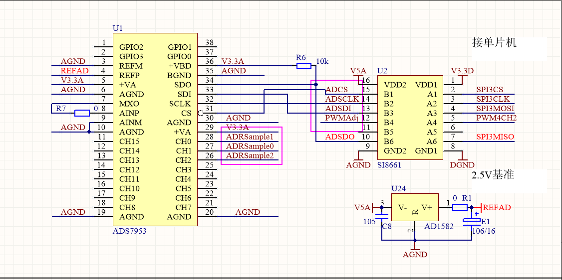
时钟频率=2.5M;时钟空闲为低,时钟上降沿采集AD数据和传数;
*******************************************************************************/
void SPI3_ADS7953_Config(void)
{
GPIO_InitTypeDef GPIO_InitStructure;
SPI_InitTypeDef SPI_InitStructure;
RCC_APB1PeriphClockCmd(RCC_APB1Periph_SPI3,ENABLE); //使能时钟
//配置引脚:PD0为CS,
GPIO_InitStructure.GPIO_Pin = GPIO_Pin_0;//
GPIO_InitStructure.GPIO_Mode = GPIO_Mode_OUT;//
GPIO_InitStructure.GPIO_OType = GPIO_OType_PP;//í?íìê?3?
GPIO_InitStructure.GPIO_Speed = GPIO_Speed_100MHz;//100MHz
GPIO_InitStructure.GPIO_PuPd = GPIO_PuPd_UP;//é?à-
GPIO_Init(GPIOD, &GPIO_InitStructure);//3?ê??ˉ
//配置特殊引脚,PC10:为SPISCLK,PC11:SPIMISO,PC12:SPIMOSI
GPIO_InitStructure.GPIO_Pin = GPIO_Pin_10 | GPIO_Pin_11 | GPIO_Pin_12;//PC10~12?′ó?1|?üê?3?
GPIO_InitStructure.GPIO_Mode = GPIO_Mode_AF;//?′ó?1|?ü
GPIO_InitStructure.GPIO_OType = GPIO_OType_PP;//í?íìê?3?
GPIO_InitStructure.GPIO_Speed = GPIO_Speed_100MHz;//100MHz
GPIO_InitStructure.GPIO_PuPd = GPIO_PuPd_UP;//é?à-
GPIO_Init(GPIOC, &GPIO_InitStructure);//3?ê??ˉ
GPIO_PinAFConfig(GPIOC,GPIO_PinSource10,GPIO_AF_SPI3); //PC10?′ó??a SPI3
GPIO_PinAFConfig(GPIOC,GPIO_PinSource11,GPIO_AF_SPI3); //PC11?′ó??a SPI3
GPIO_PinAFConfig(GPIOC,GPIO_PinSource12,GPIO_AF_SPI3); //PC12?′ó??a SPI3
RCC_APB1PeriphResetCmd(RCC_APB1Periph_SPI3,ENABLE);//?′??SPI1
RCC_APB1PeriphResetCmd(RCC_APB1Periph_SPI3,DISABLE);//í£?1?′??SPI1
SPI_InitStructure.SPI_Direction = SPI_Direction_2Lines_FullDuplex; //éè??SPIμ¥?ò?ò?????òμ?êy?Y?£ê?:SPIéè???a???????òè???1¤
SPI_InitStructure.SPI_Mode = SPI_Mode_Master; //éè??SPI1¤×÷?£ê?:éè???a?÷SPI
SPI_InitStructure.SPI_DataSize = SPI_DataSize_16b ; //16Bit长度
SPI_InitStructure.SPI_CPOL = SPI_CPOL_Low; //时钟空闲为低
SPI_InitStructure.SPI_CPHA = SPI_CPHA_1Edge; //第一个边沿(上升沿)采集数据
SPI_InitStructure.SPI_NSS = SPI_NSS_Soft; //NSSD?o?óéó2?t£¨NSS1ü??£??1ê?èí?t£¨ê1ó?SSI??£?1üàí:?ú2?NSSD?o?óDSSI??????
SPI_InitStructure.SPI_BaudRatePrescaler = SPI_BaudRatePrescaler_16; //?¨ò?2¨ì??ê?¤·??μμ??μ:2¨ì??ê?¤·??μ?μ?a32:40/16=2.5
SPI_InitStructure.SPI_FirstBit = SPI_FirstBit_MSB; //???¨êy?Y′?ê?′óMSB???1ê?LSB???aê?:êy?Y′?ê?′óMSB???aê?
SPI_InitStructure.SPI_CRCPolynomial = 7; //CRC?μ????μ??à??ê?
SPI_Init(SPI3, &SPI_InitStructure); //?ù?YSPI_InitStruct?D???¨μ?2?êy3?ê??ˉíaéèSPIx??′??÷
SPI_Cmd(SPI3, ENABLE); //ê1?üSPIíaéè
}
u16 SPI3H_SendByte(u16 byte)
{
u16 Result;
while(SPI_I2S_GetFlagStatus(SPI3,SPI_I2S_FLAG_TXE) == RESET);
SPI_I2S_SendData(SPI3, byte);
while (SPI_I2S_GetFlagStatus(SPI3,SPI_I2S_FLAG_RXNE) == RESET);
Result = SPI_I2S_ReceiveData(SPI3);
return Result;
}
/*
手动采集AD,CMD = 0x1840;Ch为通道号
*/
u16 SampleAD_ByManual_Mode(u16 Ch,u16 CMD)
{
u16 ChTemp = 0;
u16 SampleAD = 0;
ChTemp = Ch;
ChTemp = ChTemp<<7;
ChTemp = ChTemp | CMD;
CS_AD_L;//片选为低
Delay_Time(200);//延时
SampleAD = SPI3H_SendByte(ChTemp);
Delay_Time(200);//延时
CS_AD_H;//片选为高
return SampleAD;
}
/*
ManualAD = 0x1140
*/
void Initilzie_Sample_AD(void)
{
u16 i = 0;
u16 Ch = 0;
u16 SampleAD[3]={0,0,0};
u16 StartT;
while(i<3)
{
StartT = GlobalVariable.RealTimer;
while(UniversalTimer(StartT)<2);//延时20ms
SampleAD[i] = SampleAD_ByManual_Mode(i,ManualAD);
Ch = SampleAD[i] & 0xF000;
Ch = Ch>>12;
if(Ch==i)
{
i++;
}
}
}
int main(void)
{
u16 StartT;
SPI3_ADS7953_Config();
while(1)
{
StartT = GlobalVariable.RealTimer;
while(UniversalTimer(StartT)<10);//延时100ms
Initilzie_Sample_AD();
}
}
方法2
#define CS_AD_H GPIOD->ODR = GPIOD->ODR | 0x0001
#define CS_AD_L GPIOD->ODR = GPIOD->ODR & 0xFFFE
#define *** GPIOC->ODR = GPIOC->ODR | 0x0400
#define *** GPIOC->ODR = GPIOC->ODR & 0xFBFF
#define SPIMO_H GPIOC->ODR = GPIOC->ODR | 0x1000
#define SPIMO_L GPIOC->ODR = GPIOC->ODR & 0xEFFF
#define ReadADBit GPIOC->IDR & 0x0800
void GPIO_Configure_Initial(void)
{
GPIO_InitTypeDef GPIO_InitStructure;
GPIO_InitStructure.GPIO_Pin = GPIO_Pin_0;//PD0:CS
GPIO_InitStructure.GPIO_Mode = GPIO_Mode_OUT;//
GPIO_InitStructure.GPIO_OType = GPIO_OType_PP;//
GPIO_InitStructure.GPIO_Speed = GPIO_Speed_100MHz;//
GPIO_InitStructure.GPIO_PuPd = GPIO_PuPd_UP;//
GPIO_Init(GPIOD, &GPIO_InitStructure);//
GPIO_InitStructure.GPIO_Pin = GPIO_Pin_10 | GPIO_Pin_12;//PC10 SCLK,PC12:MOSI
GPIO_InitStructure.GPIO_Mode = GPIO_Mode_OUT;//
GPIO_InitStructure.GPIO_OType = GPIO_OType_PP;//
GPIO_InitStructure.GPIO_Speed = GPIO_Speed_100MHz;//
GPIO_InitStructure.GPIO_PuPd = GPIO_PuPd_UP;//
GPIO_Init(GPIOC, &GPIO_InitStructure);//
GPIO_InitStructure.GPIO_Pin = GPIO_Pin_11;//PC11:MISO
GPIO_InitStructure.GPIO_Mode = GPIO_Mode_IN;//
GPIO_InitStructure.GPIO_Speed = GPIO_Speed_100MHz;//
GPIO_InitStructure.GPIO_PuPd = GPIO_PuPd_UP;//
GPIO_Init(GPIOC, &GPIO_InitStructure);//
}
//用IO模拟SPI时钟读写数据
u16 SPI3H_SendByte(u16 byte)
{
u16 i,j;
u16 WData = 0;
u16 RData = 0;
WData = byte;
***;
for(i=0;i<16;i++)
{
if((WData & 0x8000)==0)
{
SPIMO_L;
}
else
{
SPIMO_H;
}
for(j=0;j<5;j++);
***;
for(j=0;j<5;j++);
***;
if((ReadADBit)==0)//读取数据输入的Bit
{
RData = RData & 0xFFFE;
}
else
{
RData = RData | 0x0001;
}
RData = RData<<1;
WData = WData<<1;
}
return RData;
}
void Initilzie_Sample_AD(void)
{
u16 i = 0;
u16 Ch = 0;
u16 SampleAD[3]={0,0,0};
u16 StartT;
while(i<3)
{
StartT = GlobalVariable.RealTimer;
while(UniversalTimer(StartT)<2);//延时20ms
SampleAD[i] = SampleAD_ByManual_Mode(i,ManualAD);
Ch = SampleAD[i] & 0xF000;
Ch = Ch>>12;
if(Ch==i)
{
i++;
}
}
}
int main(void)
{
u16 StartT;
Initialize_SREG_Configuration();
while(1)
{
StartT = GlobalVariable.RealTimer;
while(UniversalTimer(StartT)<10);//延时100ms
Initilzie_Sample_AD();
}
}
/*
问题描述:
方法1采用SPI模块配置采样结果:SampleAD[0]:0x0211(AD引脚电压为0.530V),SampleAD[1]:0x13C0(AD引脚电压为1.030V),SampleAD[1]:0x2AA0(AD引脚电压为4.010V)
方法2用普通IO模拟SPI时钟采样,只能采样通道0,其结果也不对;完后采样通道1前四位始终指示的是2通道
*/


