This thread has been locked.

If you have a related question, please click the "Ask a related question" button in the top right corner. The newly created question will be automatically linked to this question.

ADS1115 ALERT 如何获取 手册中的Figure 28 波形

Other Parts Discussed in Thread: ADS1115, ADS1114

我使用AIN0 ,作为输入源

配置如下:

1.Config 寄存机 high Byte 0x42 ,low Byte 0xF8;

 2.设置 阈值: LowThresholdValue 1800,HighThresholdValue 2500

3. 输入源变化,ADS1115 Conversion data检测值在 1200-3000变化,ALERT 引脚输出无变化,一直输出低电平。

请问如何设置, ALert才能得到下图波形

  • 我只需要 ALERT 功能。 

    Continous-conversion mode 下

    COMP_MODE  :置0设置为Traditional mode;

    COMP_POL  :置0 active low

    COMP_LAT:置0 Non-latching comparator

    COMP_QUE[1:0] :10 

    设置阈值

    LowThreshold = 1220

    highThreshold = 1280

    用直流源模拟输入:ADC 采样由1800-1000,ALERT 一直为低电平。并未出现手册中 Figure 28 图形

    另外:我将Hi_thresh register MSB to 1 and the Lo_thresh register MSB to 0 。ALERT pin是有连续的波形产生的,说明电路,CPU和ads1115通信 正常。

    我的需求就是,ADC采样值超出阈值后,ALERT pin有电平变化

  • 您好,您看下您的配置,是不是这里的问题,Hi_thresh register MSB to 1 and the Lo_thresh register MSB to 0 , 这里Hi_thresh 的MSB为1的话,那么您设置的highThreshold = 1280, MSB为0 就不是1了,如果MSB是1的话,举例highThreshold =0X8000.
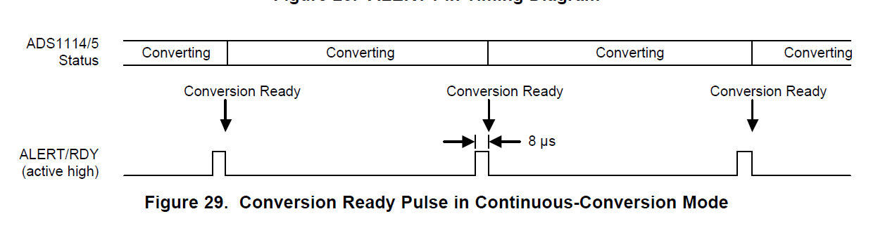
  • 感谢回复!文档9.3.8 Conversion Ready Pin (ADS1114 and ADS1115 Only)提到 :The ALERT/RDY pin can also be configured as a conversion ready pin. Set the most-significant bit of the Hi_thresh register to 1 and the most-significant bit of Lo_thresh register to 0 to enable the pin as a conversion ready pin。 Hi_thresh register MSB to 1 and the Lo_thresh register MSB to 0 这个用法是用在conversion-ready 功能。
    文档9.6.4 同样提到 :The conversion-ready function of the ALERT/RDY pin is enabled by setting the Hi_thresh register MSB to 1 and
    the Lo_thresh register MSB to 0.
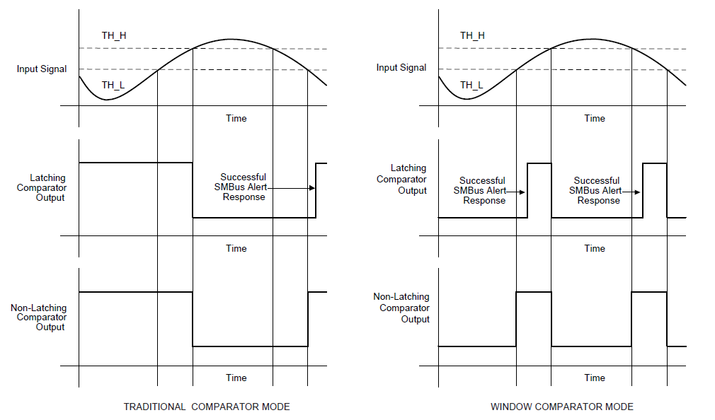
    To use the comparator function of the ALERT/RDY pin, the Hi_thresh register value must always be greater than the Lo_thresh register value.
  • ALERT/RDY pin 有 ALERT 和 RDY 两种功能。请问这两种功能的 Hi_thresh 和 Lo_thresh分别如何配置呢?
  • 文档中 这两部分的介绍中,ALERT/RDY pin 作为conversion ready功能的话,需要Hi_thresh register MSB to 1 and the Lo_thresh register MSB to 0 。

    在数字比较器中的话,Hi_thresh register 配置的值大于 Lo_thresh register 的值即可。
  • 首先,非常感谢您的回复!

    1.如果 Hi_thresh register MSB 设置为 1,Hi_thresh 一定会 大于 Lo_thresh。那么 RDY 功能如何设置这两个阈值寄存器。

    2.我设置了Hi_thresh register MSB 为1 

    void SetADS1115_ThresholdValue(uint16_t LowThresholdValue,uint16_t HighThresholdValue)
    {
    uint8_t writeData[3] = {0};

    writeData[0] = 0x02; //Lo_thresh register
    writeData[1] = LowThresholdValue >> 8;

    writeData[1]  &= 0x7F;// msb 0

    writeData[2] = LowThresholdValue &0xff;


    if((HAL_I2C_Master_Transmit(&hi2c2, I2C_ADS1115_SLAVE_ADDRESS, writeData, 3, 2000)!= HAL_OK))
    {
    printf(" SetADS1115_ThresholdValue error\r\n");
    return ;
    }
    HAL_Delay(10);
    memset(writeData,0,3);
    writeData[0] = 0x03; //Hi_thresh register
    writeData[1] = HighThresholdValue >> 8;
    writeData[1] |= 0x80;   //MSB 置1
    writeData[2] = HighThresholdValue &0xff;
    if((HAL_I2C_Master_Transmit(&hi2c2, I2C_ADS1115_SLAVE_ADDRESS, writeData, 3, 2000)!= HAL_OK))
    {
    printf(" SetADS1115_ThresholdValue error\r\n");
    return ;
    }

    两个寄存器的值

    SetADS1115_ThresholdValue(1500,1800);

    输入源是1.2V直流源, ALERT PIN 输出波形如下

    和下图RDY 类似

    这个问题,还请回复

  • 您好, 按照datasheet中的描述, conversion ready 的enable条件就是Hi_thresh register MSB to 1 and the Lo_thresh register MSB to 0.

    只有在做比较器功能的时候,需要Hi_thresh register 大于 Lo_thresh register 的值即可,就没有Hi_thresh register MSB to 1 and the Lo_thresh register MSB to 0.这个条件了。

    所以ready 功能, 这两个寄存器的值保证Hi_thresh register MSB 为1, Lo_thresh register MSB 为0 即可。

    如果使用比较器功能,这两个寄存器的配置,只要保证Hi_thresh register > Lo_thresh register 的值。

    如果还有哪里不清楚的话,我这边再帮您确认。

  • 感谢回复。我这边这个问题已经是第2周了。我需要使用的就是比较器功能,保证了 Hi_thresh register > Lo_thresh register 的值。

    传感器模式:连续采样

    比较器模式:传统模式或窗口模式

    比较次数:1-4次

    做了上面的配置,输入源电压无论如何变化(从小于Lo_thresh  到大于Hi_thresh ),ALERT 引脚无波形变化

    我们可以微信联系 15601756551 或电话联系一下吗?1天一答,快2周了。谢谢!

  • 您好,比较器功能我认为配置没有问题。我这边尽快帮您确认下, 给您带来不便非常抱歉。
  • 您好,关于您的问题,请确认两点, 第一就是先确认high register和low register这两个寄存器的值是否正确,第二就是Alert pin是否有上拉?

    There are only two things that I can think of offhand. First, I'd like the customer to read back the threshold registers. If they are set to the default settings, then it's possible that they have an error in the write of the registers. They should verify both threshold registers. They could also set the high register to 0000h and the low register to 7FFF. This would cause the ALERT/RDY to trigger at each conversion.

    The second thing that they should check is the connections to the ALERT/RDY pin. This pin does not have an active output and requires a pullup resistor (similar to SDA and SCL).
  • 你好!

    配置时high register 2500  low register 1800;

    Alert pin 有上拉电阻;

    能否电话给您说明一下 15601756551(微信也是这个)