This thread has been locked.
If you have a related question, please click the "Ask a related question" button in the top right corner. The newly created question will be automatically linked to this question.
按照TI的UC2844的文档里面搭建的电路,输出纹波比较大。
4脚的频率是78K,上面的纹波的频率是39K和PWM频率是一样的。但是纹波幅度太大了。这个是不是1脚和2脚的反馈引起的呢?怎么解决?
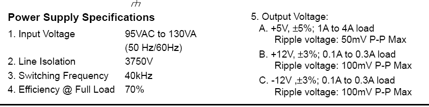
且图31对应的输出中表明了输出纹波也有100mV,这个太大了吧。
Hi, 请问你是怎么测纹波?示波器带宽为多少?建议参考以下方式测纹波:
你好,
看一下开关管的开关波形是否稳定,如果稳定那纹波和控制器本身没有关系,而是和变压器寄生、PCB走线和滤波元件有关。看图中纹波频率有点高,建议先确认示波器通道带宽打在20MHz,此外可以在输出加一个0.1uF小电容也会改善。
UC2844的6脚输出的PWM波形的占空比是在不断的调整,我的理解是如果开关电源稳定后,此处的PWM波形占空比应该是固定的。
测试方法应该没问题吧。
干扰的频率40K和PWM的频率是一样的。
如果开关波形抖动厉害,建议你测一下环路是否稳定。
这个不是纹波,是开关过程中产生的噪声,一般是由于测试方法不规范引起的。
环路?误差放大器那个反馈环路还是3脚的电流环?这两个都测过,都出现这个干扰。
是不是误差放大器在调整导致的这个问题?
但是PWM的占空比是在不断变化的,不稳定。理论上来说,开关电源正常工作后PWM波形占空比应该是固定的一个值吧。只有负载变化的时候PWM波占空比才会调整,到最后还是稳定的。
Hi
类似这样设计,本身纹波就是偏大的,这个和你上面看到的设计规格就知道,12V的纹波是100mV.
如果你希望小一点,建议你建议在输出整流管上增加RC电路, 以及在输出再增加LC.。
也就是说是反馈调节的一个结果?能不能调整一下反馈让它幅度小一点?有没有什么软件可以仿真一下?
记得以前做Adaptor之类的反激,一般12V输出纹波定义一般都是小于120mV, 但是实际小于120mV。按照上面的规格,100mV还好。
调节反馈,特别是这类用变压器输出做反馈,我觉得像做得特别低很难。(你也可以尝试通过将绕组出来的电压将纹波滤小一些看看效果)
如果是真的需要很低的niose, 除了之前提到的外,还可以在输出增加LDO。
这个情况下,6脚的PWM占空比是不断变化的吗?我记得以前做的用UC2842+PC817+TL431做的PWM波形占空比是稳定的。可是我现在的不是稳定的。我现在的纹波幅度有正负1V。如果能降到100mv我也不纠结了。
PWM当然是稳定的。
如果是到了+/-1V,确实要看反馈,包括这一块的layout影响。(估计你测试到的反馈那边波动也很严重)
是的。反馈那边的波动一样。主要是误差放大器这一块吗。
您好。我看了一下,UC2844的工作电压一般是15V,如果按15V算的话,图中2脚的电压开始是2.8V对吗?(15*R4/(R3+R4))= 2.8V. 这个有关系吗?
环路不稳定主要是和连接1脚的补偿网络参数有关,建议测试下环路,然后对着波特图修改补偿网络。
看波形spike并不是开关分量,所以跟布局和测试方式有关
那UC2844的6脚PWM占空比在不断变化。这个怎么解释呢?
对着伯特图修改补偿参数,这个怎么操作啊?有没有什么参考说明?或者仿真?
推荐一个TI官方关于环路补偿和测试的系列培训视频给你:http://training.eeworld.com.cn/TI/video/397。第八讲是关于如何测试环路的,希望可以帮助到你。
好的。感谢!
您好。在应用笔记U-100A里面提到的unitrode的U-96这篇文档哪里可以找到?好多文档都说到这个文档了但是找不到。