If you have a related question, please click the "Ask a related question" button in the top right corner. The newly created question will be automatically linked to this question.
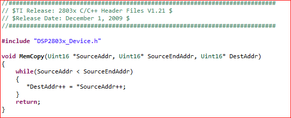
#include "DSP280x_Device.h" // DSP280x Headerfile Include File #include "DSP280x_Examples.h" // DSP280x Examples Include File
// Configure which ePWM timer interrupts are enabled at the PIE level: // 1 = enabled, 0 = disabled #define PWM3_INT_ENABLE 1
// Configure the period for each timer #define PWM3_TIMER_TBPRD 0x1FFF
// Make this long enough so that we can see an LED toggle #define DELAY 1000000L #define DELAY1 100000L
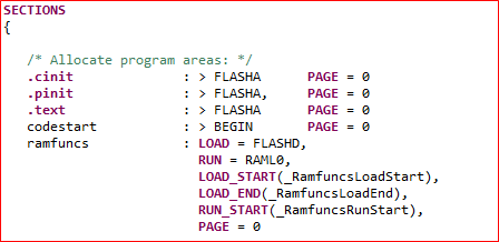
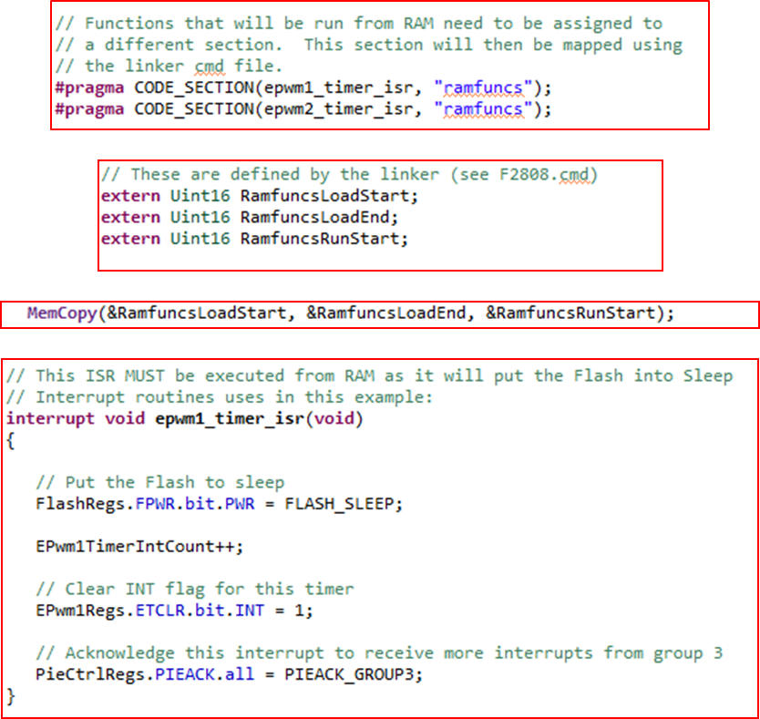
// Functions that will be run from RAM need to be assigned to // a different section. This section will then be mapped using // the linker cmd file. #pragma CODE_SECTION(epwm3_timer_isr, "ramfuncs"); // Prototype statements for functions found within this file.
interrupt void epwm3_timer_isr(void); void InitEPwmTimer(void); void Gpio_select(void); // Global variables used in this example Uint32 EPwm1TimerIntCount; Uint32 EPwm2TimerIntCount; Uint32 EPwm3TimerIntCount; Uint32 LoopCount;
// These are defined by the linker (see F2808.cmd) extern Uint16 RamfuncsLoadStart; extern Uint16 RamfuncsLoadEnd; extern Uint16 RamfuncsRunStart;
void main(void) {
// Step 1. Initialize System Control: // PLL, WatchDog, enable Peripheral Clocks // This example function is found in the DSP280x_SysCtrl.c file. InitSysCtrl();
// Step 2. Initalize GPIO: // This example function is found in the DSP280x_Gpio.c file and // illustrates how to set the GPIO to it's default state. // InitGpio(); // Skipped for this example EALLOW; GpioCtrlRegs.GPAMUX1.all = 0x0; // GPIO pin GpioCtrlRegs.GPADIR.all = 0xFF; // Output pin GpioDataRegs.GPADAT.all =0xFF; // Close LEDs EDIS;
// For this example use the following configuration: Gpio_select();
// Step 3. Clear all interrupts and initialize PIE vector table: // Disable CPU interrupts DINT;
// Initialize the PIE control registers to their default state. // The default state is all PIE interrupts disabled and flags // are cleared. // This function is found in the DSP280x_PieCtrl.c file. InitPieCtrl();
// Disable CPU interrupts and clear all CPU interrupt flags: IER = 0x0000; IFR = 0x0000;
// Initialize the PIE vector table with pointers to the shell Interrupt // Service Routines (ISR). // This will populate the entire table, even if the interrupt // is not used in this example. This is useful for debug purposes. // The shell ISR routines are found in DSP280x_DefaultIsr.c. // This function is found in DSP280x_PieVect.c. InitPieVectTable();
// Interrupts that are used in this example are re-mapped to // ISR functions found within this file. EALLOW; // This is needed to write to EALLOW protected registers // PieVectTable.EPWM1_INT = &epwm1_timer_isr; // PieVectTable.EPWM2_INT = &epwm2_timer_isr; PieVectTable.EPWM3_INT = &epwm3_timer_isr; EDIS; // This is needed to disable write to EALLOW protected registers
// Step 4. Initialize all the Device Peripherals: // This function is found in DSP280x_InitPeripherals.c // InitPeripherals(); // Not required for this example InitEPwmTimer(); // For this example, only initialize the ePWM Timers MemCopy(&RamfuncsLoadStart, &RamfuncsLoadEnd, &RamfuncsRunStart);
// Call Flash Initialization to setup flash waitstates // This function must reside in RAM InitFlash();
// Enable CPU INT3 which is connected to EPWM1-3 INT: IER |= M_INT3;
// Enable EPWM INTn in the PIE: Group 3 interrupt 1-3 PieCtrlRegs.PIEIER3.bit.INTx3 = PWM3_INT_ENABLE;
// Enable global Interrupts and higher priority real-time debug events: EINT; // Enable Global interrupt INTM ERTM; // Enable Global realtime interrupt DBGM
// Step 6. IDLE loop. Just sit and loop forever (optional): EALLOW; GpioCtrlRegs.GPBMUX1.bit.GPIO34 = 0; GpioCtrlRegs.GPBDIR.bit.GPIO34 = 1; EDIS;
for(;;) { // This loop will be interrupted, so the overall // delay between pin toggles will be longer. DELAY_US(DELAY); LoopCount++; GpioDataRegs.GPBTOGGLE.bit.GPIO34 = 1; }
}
void InitEPwmTimer() {
EALLOW; SysCtrlRegs.PCLKCR0.bit.TBCLKSYNC = 0; // Stop all the TB clocks EDIS;
// Setup Sync EPwm3Regs.TBCTL.bit.SYNCOSEL = TB_SYNC_IN; // Pass through // Allow each timer to be sync'ed EPwm3Regs.TBCTL.bit.PHSEN = TB_ENABLE; EPwm3Regs.TBPHS.half.TBPHS = 300; EPwm3Regs.TBPRD = PWM3_TIMER_TBPRD; EPwm3Regs.TBCTL.bit.CTRMODE = TB_COUNT_UP; // Count up EPwm3Regs.ETSEL.bit.INTSEL = ET_CTR_ZERO; // Enable INT on Zero event EPwm3Regs.ETSEL.bit.INTEN = PWM3_INT_ENABLE; // Enable INT EPwm3Regs.ETPS.bit.INTPRD = ET_3RD; // Generate INT on 3rd event
EALLOW; SysCtrlRegs.PCLKCR0.bit.TBCLKSYNC = 1; // Start all the timers synced EDIS;
}
interrupt void epwm3_timer_isr(void) { Uint16 i;
EPwm3TimerIntCount++;
// Short Delay to simulate some ISR Code for(i = 1; i < 0x01FF; i++) {} GpioDataRegs.GPADAT.all=0xFFFDFFFF; //GPIO17=0 LED灯亮 DELAY_US(DELAY1); GpioDataRegs.GPADAT.all=0xFFF7FFFF; //GPIO19=0 DELAY_US(DELAY1); // Clear INT flag for this timer EPwm3Regs.ETCLR.bit.INT = 1;
// Acknowledge this interrupt to receive more interrupts from group 3 PieCtrlRegs.PIEACK.all = PIEACK_GROUP3; }