Other Parts Discussed in Thread: MSP430FR5739
下面是我的串口程序,不知道哪里设置不对,调试不出来,用的是TI的pad,没有外接晶振
#include "msp430fr5739.h"
#define delayus(n) __delay_cycles(n)
void Uart_Init(void)
{
P2SEL1 |= BIT0 + BIT1;
P2SEL0 &= ~(BIT0 + BIT1); // P2.0,1 = USART0 TXD/RXD 选择端口用作接收和发送端口
UCA0CTL1 |= UCSWRST;
UCA0CTL1 = UCSSEL_2; // Set SMCLK as UCLk
UCA0BR0 = 52 ; // 9600 baud
// 8000000/(9600*16) - INT(8000000/(9600*16))=0.083
UCA0BR1 = 0;
// UCBRFx = 1, UCBRSx = 0x49, UCOS16 = 1 (Refer User Guide)
//UCA0MCTLW = 0x4911 ;
UCA0MCTLW = 0x0411 ;
UCA0CTL1 &= ~UCSWRST; // release from reset
UCA0IE |= UCRXIE; // 使能 USART0 RX 中断
}
void Uart_Put_Char(unsigned char c)
{
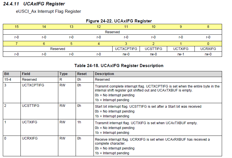
while (!(UCA0IFG&UCTXIFG)); //等待发送寄存器为空
UCA0TXBUF = c;
}
void Uart_Put_string(unsigned char *ptr)
{
while(*ptr != '\0')
{
Uart_Put_Char(*ptr++); // 发送数据
}
}
void main(void)
{
CSCTL0_H = 0xA5;
CSCTL1 |= DCORSEL + DCOFSEL0 + DCOFSEL1; // Set max. DCO setting
CSCTL2 = SELA_1 + SELS_3 + SELM_3; // set ACLK - VLO, the rest = MCLK = DCO
CSCTL3 = DIVA_0 + DIVS_0 + DIVM_0; // set all dividers to 0
Uart_Init();
while(1)
{
Uart_Put_string( "Sf");
delayus(5000000);
delayus(5000000);
delayus(5000000);
}
}