If you have a related question, please click the "Ask a related question" button in the top right corner. The newly created question will be automatically linked to this question.
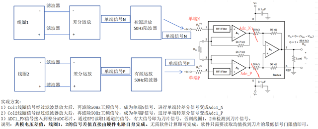
Implementation plan: 1) After being amplified by a filter, the Col1 coil signal is filtered to remove the 50Hz power frequency signal, becoming a single-ended N signal. It is then converted from a single-ended signal to a differential signal, resulting in Adc1_N 2) After being amplified by a filter, the Col2 coil signal is filtered to remove the 50Hz power frequency signal, becoming a single-ended P signal. It is then converted from a single-ended signal to a differential signal, resulting in Adc1_P 3) The ADC1_PN signal is connected to the differential ADC chip, and the signal of channel 1 is read through SPI. If there is a large signal, it indicates the presence of a blade signal. Otherwise, coil 1 and coil 2 do not detect the blade signal. Description: The common mode voltage difference and signal difference between coils 1 and 2 are directly calculated by the hardware circuit itself. No software calculation is required. The software only needs to read the average value to find the lowest signal threshold of the blade.
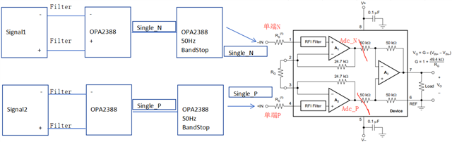
Implementation plan: 1) After being amplified by a filter, the Col1 coil signal is filtered to remove the 50Hz power frequency signal, becoming a single-ended N signal. It is then converted from a single-ended signal to a differential signal, resulting in Adc1_N 2) After being amplified by a filter, the Col2 coil signal is filtered to remove the 50Hz power frequency signal, becoming a single-ended P signal. It is then converted from a single-ended signal to a differential signal, resulting in Adc1_P 3) The ADC1_PN signal is connected to the differential ADC chip, and the signal of channel 1 is read through SPI. If there is a large signal, it indicates the presence of a blade signal. Otherwise, coil 1 and coil 2 do not detect the blade signal. Description: The common mode voltage difference and signal difference between coils 1 and 2 are directly calculated by the hardware circuit itself. No software calculation is required. The software only needs to read the average value to find the lowest signal threshold of the blade.
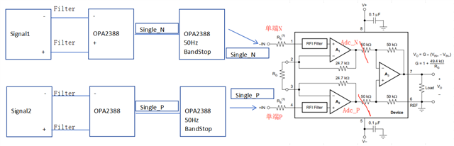
Implementation plan: 1) After being amplified by a filter, the Col1 coil signal is filtered to remove the 50Hz power frequency signal, becoming a single-ended N signal. It is then converted from a single-ended signal to a differential signal, resulting in Adc1_N 2) After being amplified by a filter, the Col2 coil signal is filtered to remove the 50Hz power frequency signal, becoming a single-ended P signal. It is then converted from a single-ended signal to a differential signal, resulting in Adc1_P 3) The ADC1_PN signal is connected to the differential ADC chip, and the signal of channel 1 is read through SPI. If there is a large signal, it indicates the presence of a blade signal. Otherwise, coil 1 and coil 2 do not detect the blade signal. Description: The common mode voltage difference and signal difference between coils 1 and 2 are directly calculated by the hardware circuit itself. No software calculation is required. The software only needs to read the average value to find the lowest signal threshold of the blade.
It's impossible to follow your description since you refer to multiple nodes like Col1, Col2, Adc1_N, Adc2_P and ADC1_PN, which do NOT show on your schematic.Also, it would help to show actual filter circuit instead of boxes with filter name. I presume that the power frequency interference occurs in the circuit you do not show and if so you need to show entire schematic in order to assist you since the best way to deal with such interference is to prevent it from feeding into the signal path in the first place.