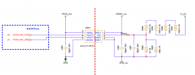
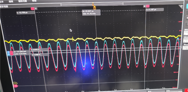
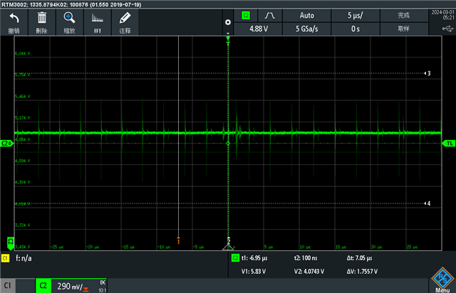
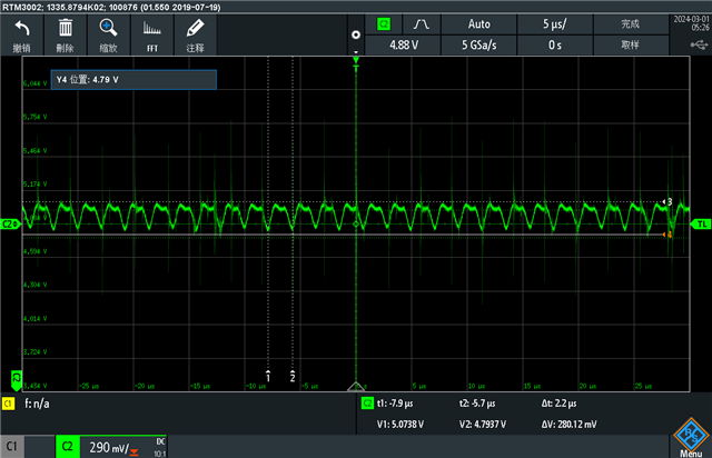
Hello, the schematic diagram is shown below. We want to use AMC1311B-Q1 to achieve the DC bus voltage sampling function. In the schematic diagram, C_UH-GND_UL is the DC bus voltage. When the bus voltage is 0, the differential signal waveform at the output end of AMC1311B-Q1 is tested as shown in the figure. Theoretically, it should be a DC signal, but the test result shows a sine signal. What is the reason for this?