This thread has been locked.
If you have a related question, please click the "Ask a related question" button in the top right corner. The newly created question will be automatically linked to this question.
Hi,
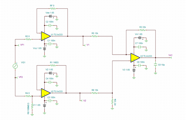
有个问题想咨询一下,在进行电路设计前我用Tina-TI做了电路仿真,输入信号±500mV,输出符合设计需求。
但是在拿到PCB后。输入信号是直流200mV。实际测试输出:VF1=-301mV,VF2=-500mV,V1=-503mV,V2=-420mV,与仿真结果不符,不确定哪里出了问题,麻烦帮忙分析一下,谢谢。
补充一点,最终PCB上R1为0R
R8取100MΩ,放大了IB的对输入输入的影响。
计算了下,导致的偏差可能达到30mV。并未达到你描述的程度,这可能和你真实的测试系统有关。
建议将R8降低为1MΩ或者更低,可以解决偏差问题。