TLV320AIC3104IRHBR Hello, the correspondence between the external analog amplitude and the converted one is actually artificially defined, which is adjusted by the front-end partial voltage resistor and the internal front-end analog PGA. Now the problem is that we send the signal according to the maximum analog input amplitude in the manual, and the waveform converted by the ADC will be deformed, and it is necessary to reduce the external amplitude to make the digital amplitude within the range of -3.7dbfs to achieve normal sine wave waveform.
Channel one analog gain to -3.84db, when the waveform is normal. The waveform will be deformed when the channel 2 gain reaches 0dBb. After measuring the analog gain to -3.24 is the maximum, and any further increase will cause distortion. How to configure the register so that the sound reaches 0db, and the waveform is not distorted.
Channel one analog gain to -3.84db, when the waveform is normal. The waveform will be deformed when the channel 2 gain reaches 0dBb. After measuring the analog gain to -3.24 is the maximum, and any further increase will cause distortion. How to configure the register so that the sound reaches 0db, and the waveform is not distorted.
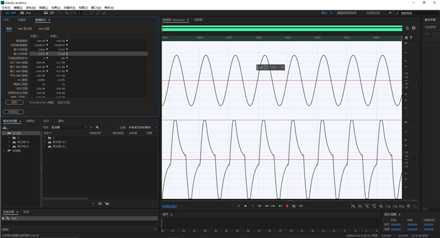 The following figure shows the waveforms before entering the 3104 chip and the analog input sources respectively
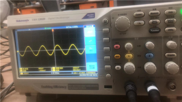
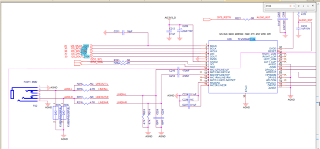
The schematic diagram is as follows: