


最近在用2812做一款控制器,需要DA转换模块,最后选择了DAC7558,设计的原理图是这个样子:
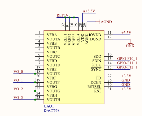
只用到了4路,因为当时设计板子的时候没有规划好,只能用普通I/O口模拟SPI,程序和波形图我会贴在后面
现在遇到了无法解决的问题,因为根据波形图来看是完全符合7558的SPI通讯要求的,硬件电路也检查过,没有问题,
但是四个输出口的电压恒为0.75伏,在不给7558写数的时侯,也是0.75伏,我找不到其他问题了,蛮烦用过这款芯片的
大神可以出来帮我看一下,非常感激~~
附件里有DAC7558的原理图:
下面是截取的DAC7558的SPI通讯时序图和数据定义:
SPI时序图:
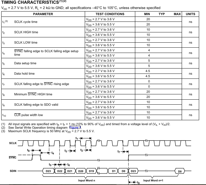
数据定义图(其中的X表示0/1都可以,我都发送的是1),发送数据时是高位先发送
波形图:(抱歉,设备有限只能一次截两个通道)
1.时钟线(上)和数据线(下)的截图

2.时钟线(上)和片选线(下)的图像

程序:(一开始想实现输出正弦波的功能,后面只是发送了一个固定的数000EC180,对应的第H通道输出3096/4095*3=2.27伏的电压,但是依然是0.75伏
#include "DSP281x_Device.h" // DSP281x Headerfile Include File
#include "DSP281x_Examples.h" // DSP281x Examples Include File
#include "math.h"
//#include "math.h"
// Prototype statements for functions found within this file.
interrupt void cpu_timer0_isr(void);
#define PI 3.1415926
#define N 100
float Sin_a[N];
Uint16 Simu_a[N];
Uint32 Data_E;
Uint32 Data_T[24];
int flag;
int p,q;
void Simu_sin(void); //SIN波形转换函数
void Data_handle(Uint16 Data_Row);
void Xmit_Init(Uint32 Data);
//void TX(void);
void main(void)
{
Uint32 i=0;
Uint32 j=0;
// Step 1. Initialize System Control:
// PLL, WatchDog, enable Peripheral Clocks
// This example function is found in the DSP281x_SysCtrl.c file.
InitSysCtrl();
{
Uint32 i=0;
Uint32 j=0;
// Step 1. Initialize System Control:
// PLL, WatchDog, enable Peripheral Clocks
// This example function is found in the DSP281x_SysCtrl.c file.
InitSysCtrl();
// Step 2. Initalize GPIO:
// This example function is found in the DSP281x_Gpio.c file and
// illustrates how to set the GPIO to it's default state.
// InitGpio(); // Skipped for this example
EALLOW;
GpioMuxRegs.GPAMUX.bit.C3TRIP_GPIOA15=0; //A15->F10 SDIN
GpioMuxRegs.GPAMUX.bit.C2TRIP_GPIOA14=0; //A14->F11 SCLK
GpioMuxRegs.GPAMUX.bit.C1TRIP_GPIOA13=0; //A13->F12 SYNC
//GpioMuxRegs.GPAQUAL.bit.QUALPRD=0xff;
GpioMuxRegs.GPADIR.bit.GPIOA15=1;
GpioMuxRegs.GPADIR.bit.GPIOA14=1;
GpioMuxRegs.GPADIR.bit.GPIOA13=1;
GpioDataRegs.GPASET.bit.GPIOA15=1;
//GpioDataRegs.GPASET.bit.GPIOA14=1;
GpioDataRegs.GPASET.bit.GPIOA13=1;
EDIS;
// Step 3. Clear all interrupts and initialize PIE vector table:
// Disable CPU interrupts
DINT;
// Initialize the PIE control registers to their default state.
// The default state is all PIE interrupts disabled and flags
// are cleared.
// This function is found in the DSP281x_PieCtrl.c file.
InitPieCtrl();
// Disable CPU interrupts and clear all CPU interrupt flags:
IER = 0x0000;
IFR = 0x0000;
// The default state is all PIE interrupts disabled and flags
// are cleared.
// This function is found in the DSP281x_PieCtrl.c file.
InitPieCtrl();
// Disable CPU interrupts and clear all CPU interrupt flags:
IER = 0x0000;
IFR = 0x0000;
// Initialize the PIE vector table with pointers to the shell Interrupt
// Service Routines (ISR).
// This will populate the entire table, even if the interrupt
// is not used in this example. This is useful for debug purposes.
// The shell ISR routines are found in DSP281x_DefaultIsr.c.
// This function is found in DSP281x_PieVect.c.
InitPieVectTable();
// Service Routines (ISR).
// This will populate the entire table, even if the interrupt
// is not used in this example. This is useful for debug purposes.
// The shell ISR routines are found in DSP281x_DefaultIsr.c.
// This function is found in DSP281x_PieVect.c.
InitPieVectTable();
// Interrupts that are used in this example are re-mapped to
// ISR functions found within this file.
EALLOW; // This is needed to write to EALLOW protected registers
PieVectTable.TINT0 = &cpu_timer0_isr;
EDIS; // This is needed to disable write to EALLOW protected registers
// ISR functions found within this file.
EALLOW; // This is needed to write to EALLOW protected registers
PieVectTable.TINT0 = &cpu_timer0_isr;
EDIS; // This is needed to disable write to EALLOW protected registers
// Step 4. Initialize all the Device Peripherals:
// This function is found in DSP281x_InitPeripherals.c
// InitPeripherals(); // Not required for this example
Simu_sin();
InitCpuTimers(); // For this example, only initialize the Cpu Timers
// This function is found in DSP281x_InitPeripherals.c
// InitPeripherals(); // Not required for this example
Simu_sin();
InitCpuTimers(); // For this example, only initialize the Cpu Timers
// Configure CPU-Timer 0 to interrupt every second:
// 100MHz CPU Freq, 1 second Period (in uSeconds)
ConfigCpuTimer(&CpuTimer0, 150, 100);
// 100MHz CPU Freq, 1 second Period (in uSeconds)
ConfigCpuTimer(&CpuTimer0, 150, 100);
// Step 5. User specific code, enable interrupts:
// Enable CPU INT1 which is connected to CPU-Timer 0:
IER |= M_INT1;
// Enable TINT0 in the PIE: Group 1 interrupt 7
PieCtrlRegs.PIEIER1.bit.INTx7 = 1;
PieCtrlRegs.PIEIER1.bit.INTx7 = 1;
// Enable global Interrupts and higher priority real-time debug events:
EINT; // Enable Global interrupt INTM
ERTM; // Enable Global realtime interrupt DBGM
EINT; // Enable Global interrupt INTM
ERTM; // Enable Global realtime interrupt DBGM
// Step 6. IDLE loop. Just sit and loop forever (optional):
while(1)
{
for(i=0;i<100;i++)
{
EALLOW;
GpioDataRegs.GPACLEAR.bit.GPIOA13=1; //片选线拉低
GpioDataRegs.GPACLEAR.bit.GPIOA15=1; //数据线拉低
GpioDataRegs.GPACLEAR.bit.GPIOA14=1; //时钟线拉低(高)
EDIS;
Data_handle(0xC180);
Xmit_Init(Data_E);
flag=0;
StartCpuTimer0(); //启动时钟
do{;}
while(!(flag==25));
StopCpuTimer0(); //转换完成,停止时钟
EALLOW;
GpioDataRegs.GPASET.bit.GPIOA13=1; //片选线拉高
GpioDataRegs.GPACLEAR.bit.GPIOA14=1; //时钟线拉(高)
GpioDataRegs.GPACLEAR.bit.GPIOA15=1; //数据线拉低
EDIS;
{
for(i=0;i<100;i++)
{
EALLOW;
GpioDataRegs.GPACLEAR.bit.GPIOA13=1; //片选线拉低
GpioDataRegs.GPACLEAR.bit.GPIOA15=1; //数据线拉低
GpioDataRegs.GPACLEAR.bit.GPIOA14=1; //时钟线拉低(高)
EDIS;
Data_handle(0xC180);
Xmit_Init(Data_E);
flag=0;
StartCpuTimer0(); //启动时钟
do{;}
while(!(flag==25));
StopCpuTimer0(); //转换完成,停止时钟
EALLOW;
GpioDataRegs.GPASET.bit.GPIOA13=1; //片选线拉高
GpioDataRegs.GPACLEAR.bit.GPIOA14=1; //时钟线拉(高)
GpioDataRegs.GPACLEAR.bit.GPIOA15=1; //数据线拉低
EDIS;
for(j=0;j<5000;j++)
{;}
}
}
{;}
}
}
}
interrupt void cpu_timer0_isr(void)
{
CpuTimer0.InterruptCount++;
EALLOW;
GpioDataRegs.GPATOGGLE.bit.GPIOA14=1;
EDIS;
if(GpioDataRegs.GPADAT.bit.GPIOA14 == 1)
{
if(Data_T[flag])
{
EALLOW;
GpioDataRegs.GPADAT.bit.GPIOA15=1; //第23-i位数据为1
EDIS;
p++;
}
else
{
EALLOW;
GpioDataRegs.GPADAT.bit.GPIOA15=0; //第23-i位数据为0
EDIS;
{
if(Data_T[flag])
{
EALLOW;
GpioDataRegs.GPADAT.bit.GPIOA15=1; //第23-i位数据为1
EDIS;
p++;
}
else
{
EALLOW;
GpioDataRegs.GPADAT.bit.GPIOA15=0; //第23-i位数据为0
EDIS;
}
flag++;
flag++;
}
// Acknowledge this interrupt to receive more interrupts from group 1
PieCtrlRegs.PIEACK.all = PIEACK_GROUP1;
}
// Acknowledge this interrupt to receive more interrupts from group 1
PieCtrlRegs.PIEACK.all = PIEACK_GROUP1;
}
//Sin波形转换
void Simu_sin(void)
{
int i=0;
float j=0;
for(i=0;i<N;i++)
{
j = (float)(i)/100*2*PI;
Sin_a[i]=sin(j);
Simu_a[i]=(Uint16)((2048*Sin_a[i]+2048))<<4;
}
}
//数据整合函数
//入口函 DAC芯片的数据位
//函数返回值 发送给DAC芯片的数据
void Data_handle(Uint16 DataRow)
{
Uint16 Data_temp_H;
Uint16 Data_temp_L;
Uint32 Data_temp=0x00000000;
Data_temp_L=DataRow&0xfff0;
Data_temp_H=0x000E;
Data_temp=(Data_temp+Data_temp_H)<<16;
Data_E=Data_temp+Data_temp_L;
//return Data_temp;
}
void Xmit_Init(Uint32 Data)
{
Uint32 Data_Handle;
{
Uint32 Data_Handle;
int i;
for(i=0;i<24;i++)
{
Data_Handle=0x00000001;
for(i=0;i<24;i++)
{
Data_Handle=0x00000001;
Data_Handle=Data_Handle<<(23-i);
Data_T[i]=Data&Data_Handle;
}
Data_T[i]=Data&Data_Handle;
}
