This thread has been locked.
If you have a related question, please click the "Ask a related question" button in the top right corner. The newly created question will be automatically linked to this question.
Other Parts Discussed in Thread: ADS1204
哪位大神用过,求指导,希望可以联系我939969820@qq.com 必有重谢
不要这样提问.
最起码你把遇到的问题描述清楚.
这里是授之于渔, 而不是授之于鱼 的地方.
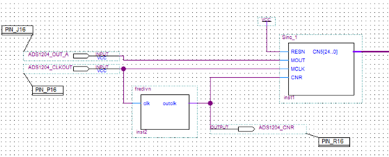
上图是我根据网上找的方法弄的,我对ads1204的输出数据滤波模块,图中ADS1204_OUT_A 代表芯片的数据输出口,ADS1204_CLKOUT 代表芯片输出时钟,fredivn表示256分频即起到OSR=256的作用,sinc_1表示sinc3滤波。请问设计思路是否正确?我测试的结果是经过滤波后输出数据变化非常大,不知道问题出在哪里,请指导,另外,我也试过CNR用外部时钟输入,依旧不行,您能指导下吗?
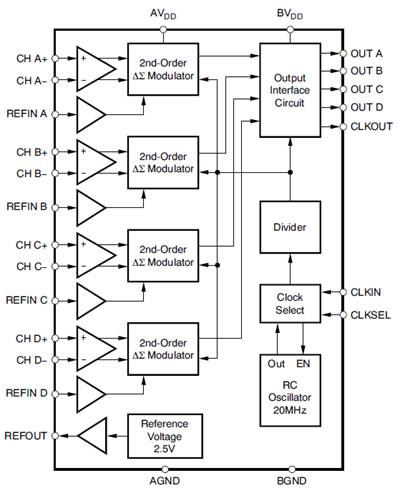
ADS1204是没有时钟输出的! 需要外部提供时钟给调制器和滤波器。
OSR = 256 与 256分频不是同一个概念吧!
你现在滤波后的结果波动范围大概为多少?在ADS1204输入短接的时候
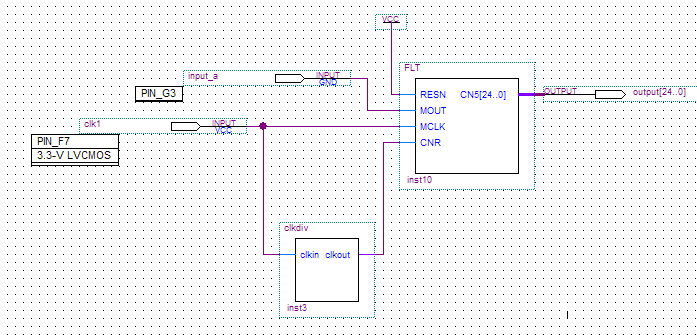
按照手册上说的,只要将CLKSEL设置为高电平就可以选用内部时钟,所以会有CLKOUT的周期为100ns,我将CLKOUT作为数字滤波器的时钟输入,再通过分频得到MCLK的输入,见下图的SINC3滤波器设计:(按照application note SBAA094中的思路设计滤波器,这是在ADS1204手册中提到的)
SINC3滤波器程序为:
library IEEE;
use IEEE.std_logic_1164.all;
use IEEE.std_logic_unsigned.all;
entity FLT is
port(RESN, MOUT, MCLK, CNR : in std_logic;
CN5 : out std_logic_vector(24 downto 0));
end FLT;
architecture RTL of FLT is
signal DN0, DN1, DN3, DN5 : std_logic_vector(24 downto 0);
signal CN1, CN2, CN3, CN4 : std_logic_vector(24 downto 0);
signal DELTA1 : std_logic_vector(24 downto 0);
begin
process(MCLK, RESn)
if RESN = '0' then
DELTA1 <= (others => '0');
elsif MCLK'event and MCLK = '1' then
if MOUT = '1' then
DELTA1 <= DELTA1 + 1;
end if;
end process;
process(RESN, MCLK)
CN1 <= (others => '0');
CN2 <= (others => '0');
CN1 <= CN1 + DELTA1;
CN2 <= CN2 + CN1;
process(RESN, CNR)
DN0 <= (others => '0');
DN1 <= (others => '0');
DN3 <= (others => '0');
DN5 <= (others => '0');
elsif CNR'event and CNR = '1' then
DN0 <= CN2;
DN1 <= DN0;
DN3 <= CN3;
DN5 <= CN4;
CN3 <= DN0 - DN1;
CN4 <= CN3 - DN3;
CN5 <= CN4 - DN5;
end RTL;
可以看到输出为25位的数据,如果我输入为0V,那么输出的变化范围为几百,十分不稳定(按照10进制),照理应该是一个定值,希望您能够指导一下!
没有人做过这个吗?求指导