


Part Number: DP83822I
Dear Team,
We got some problems in using DP83822I in our communication cards with multiple communication methods such as EtherCAT, PN-RT, PN_IRT, etc. When we powered on, packet loss or IP address loss might occur.Here the pictures show our schematic diagram and PCB layout for this chip,could you please help us to find reason of these problems?
Schematic diagram:

PHY1 TO SIGNAL TRANSFORMER1:

PHY2 TO SIGNAL TRANSFORMER2:

PHY TO DSP:

There are four questions we need to check:
1.POWER;
2.CLOCK;
3.RESET_N;
4.INTERRUPT
Details are in the schematic checklist below
DP83822_Schematic_Checklist_20260323_copyfile.rar
AS you reply before(can't find this question link):
First of all, it needs to be clarified that we are not experiencing packet loss during operation, but during the power-on process.
Meanwhile, based on the modification points you provided, we have compared them with our circuit:
1. For Rbias, we are using two resistors in parallel, with a combined resistance close to 4.87 kΩ. This was previously confirmed with you and deemed acceptable.
2. Regarding the RESET_N pin — is a pull-up resistor required? Based on TI’s reference design, we have set it as pull-down. Should it be changed to pull-up resistor?
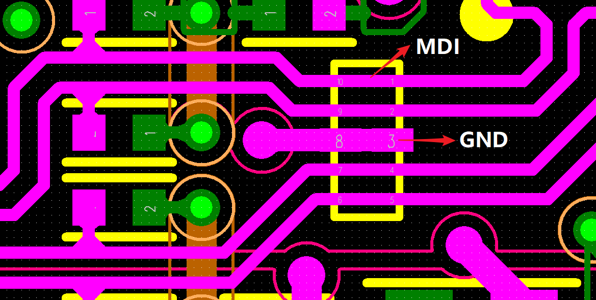
3. We have a ground plane underneath the MDI traces. However, regarding the point in the Layout Checklist: “Are ground planes on the same layer distanced at least 3× the width of the MDI trace from the MDI trace? (Recommended 5× the width of the MDI trace)” — I don’t fully understand why such a large distance is required. Could you explain? Our trace distance does not meet this 3× requirement. Could this be affecting communication during power-up?
4. Regarding the crystal oscillator: we measured the XI pin of the PHY chip. The waveform is shown in the figure. The fall time is longer than the 8 ns specified in the datasheet. Could this affect communication? (Measurements were taken using a Keysight DSOX3014G oscilloscope and Keysight N2843Z probe.)
