

Part Number: CD4013B
My circuit connection is as shown in the diagram below.
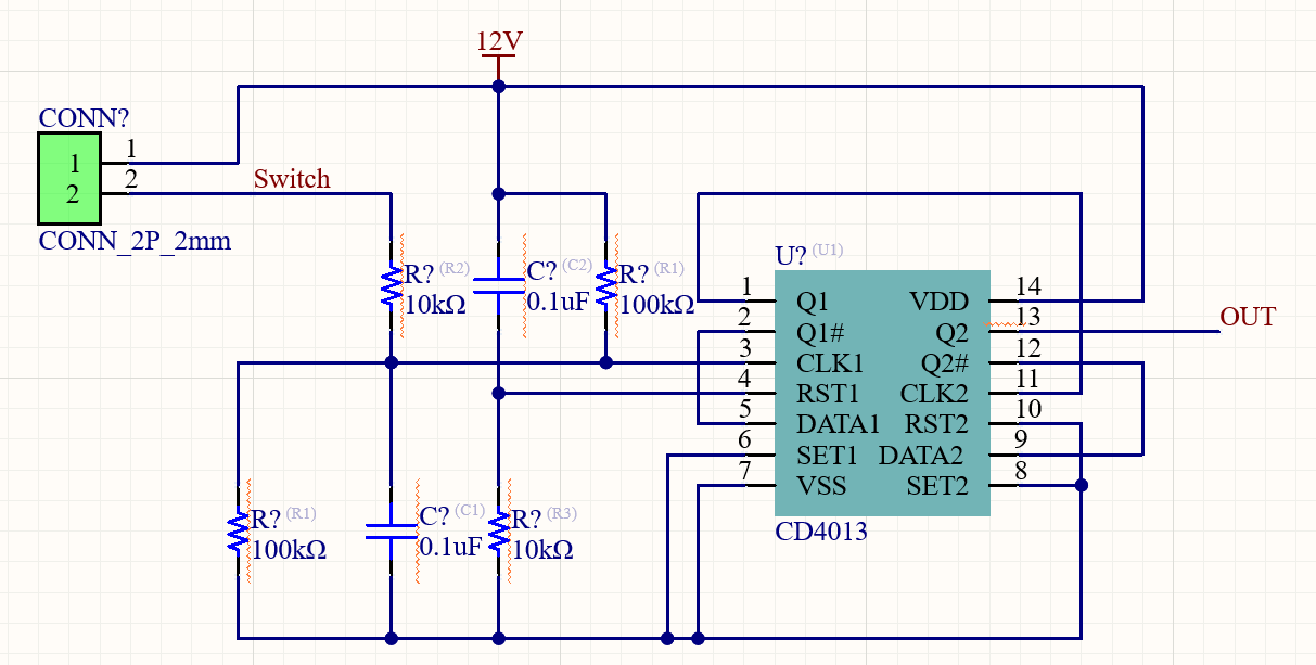
I noticed that when I use only the first channel, a special phenomenon occurs: the output of Q1 follows the level of the CLK1 signal, rather than toggling on the rising edge of CLK1. After checking the datasheet, I suspect this may be caused by an excessively long rise time of the CLK signal.

Therefore, I used the circuit connection shown in the figure, where the extremely short rise time of Q1 is used as the input for CLK2. In this case, I found that Q2 toggles normally on the rising edge of CLK1.
However, I am still concerned about whether the Q1 following behavior in the first channel is reliable. I would like to ask: what does the datasheet specify regarding the state of the CD4013 when the rise time exceeds the maximum limit? Also, if I do not use an additional Schmitt trigger, is it possible to achieve both switch debouncing and Q output toggling using only one CD4013?
Thank you for your help.
