请注意,本文内容源自机器翻译,可能存在语法或其它翻译错误,仅供参考。如需获取准确内容,请参阅链接中的英语原文或自行翻译。
您好!
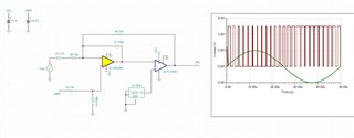
我正在尝试实现 SLAU508 模拟脉宽调制的仿真、但针对交流耦合输入进行了修改。 我从电路中删除了 R2、但根据应用程序、则输出仅在输入正弦波的负向一半上生成 PWM 输出。 交流耦合电容的误差放大器侧的信号现在似乎偏置在 VCC 周围、而不是 VCC/2 (VREF)。 我还可以如何修改电路以实现适当的交流耦合?
谢谢!
您好!
我正在尝试实现 SLAU508 模拟脉宽调制的仿真、但针对交流耦合输入进行了修改。 我从电路中删除了 R2、但根据应用程序、则输出仅在输入正弦波的负向一半上生成 PWM 输出。 交流耦合电容的误差放大器侧的信号现在似乎偏置在 VCC 周围、而不是 VCC/2 (VREF)。 我还可以如何修改电路以实现适当的交流耦合?
谢谢!