Other Parts Discussed in Thread: TM4C123GH6PM, EK-TM4C1294XL
请注意,本文内容源自机器翻译,可能存在语法或其它翻译错误,仅供参考。如需获取准确内容,请参阅链接中的英语原文或自行翻译。
器件型号:TM4C123GH6PM Thread 中讨论的其他器件: EK-TM4C1294XL
工具/软件:
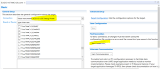
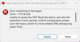
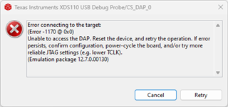
我在定制电路板上对 TM4C123GH6PM 进行编程时遇到问题。 我一直收到以下错误消息、
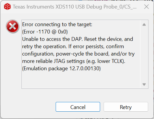
我已经尝试使用 dbgjtag.exe 重置 DAP、但其无效。

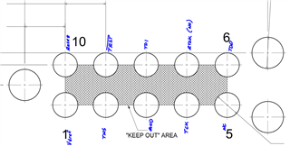
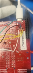
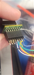
下面是 JTAG 接头的屏幕截图、
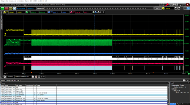
通道1 TMS、通道2 TCK、通道3 TDI、通道4 TDO。
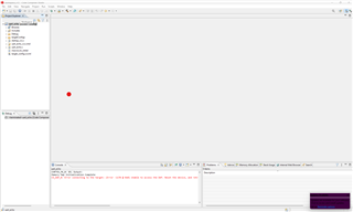
来自协议解码的数据已附加。
谢谢、