This thread has been locked.

If you have a related question, please click the "Ask a related question" button in the top right corner. The newly created question will be automatically linked to this question.

[参考译文] TM4C129XNCZAD:I2C 与 LTC4151高压 I2C 电流和电压监控器通信

Guru**** 2419530 points


请注意,本文内容源自机器翻译,可能存在语法或其它翻译错误,仅供参考。如需获取准确内容,请参阅链接中的英语原文或自行翻译。

https://e2e.ti.com/support/microcontrollers/arm-based-microcontrollers-group/arm-based-microcontrollers/f/arm-based-microcontrollers-forum/1077398/tm4c129xnczad-i2c-communication-with-ltc4151-high-voltage-i2c-current-and-voltage-monitor

部件号:TM4C129XNCZAD

大家好,我正在尝试通过 I2C 从 LTC4151获取电压数据,我似乎无法再获取这些数据。 我正在使用 TI 外设驱动程序库,每当我尝试从设备读取数据时,即使电路有电压,我的值也会为0。 我有一个定制板。 下面是代码,并在尝试读取后注册数据。

要从设备读取的代码(为 I2CMasterControl()尝试了许多不同的参数,似乎没有任何改变):

void ReadInputVoltageMonitor( void ){


    //read from the specified slave device
    I2CMasterSlaveAddrSet(I2C0_BASE, 0xde, false);

    //send control byte and read from the register from the MCU
    I2CMasterControl(I2C0_BASE, I2C_MASTER_CMD_BURST_SEND_START);

    while(I2CMasterBusy(I2C0_BASE)){

    }


    //put the target register addres into data send register.
    I2CMasterDataPut(I2C0_BASE, 0x02);

    I2CMasterControl(I2C0_BASE, I2C_MASTER_CMD_BURST_SEND_FINISH);

    while(I2CMasterBusy(I2C0_BASE)){

    }


    //read from the specified slave device
    I2CMasterSlaveAddrSet(I2C0_BASE, 0xde, true);

    I2CMasterControl(I2C0_BASE, I2C_MASTER_CMD_BURST_RECEIVE_START);

    while(I2CMasterBusy(I2C0_BASE)){

    }

    voltageValue = ((I2CMasterDataGet(I2C0_BASE) << 4) & 0xff0);


    I2CMasterControl(I2C0_BASE, I2C_MASTER_CMD_BURST_RECEIVE_FINISH);

    while(I2CMasterBusy(I2C0_BASE)){

    }

    voltageValue |= (I2CMasterDataGet(I2C0_BASE) & 0x0f);

    while(I2CMasterBusy(I2C0_BASE)){

    }
}

I2C 在该方法的末尾注册值:

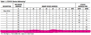
LTC4151的地址信息(图像1是设备地址,图像2是寄存器地址)

阅读 LTC4151数据表中描述的操作步骤:

Read Protocol
The master begins a read operation with a Start condition
followed by the seven bit slave address and the R/W bit
set to zero. After the addressed LTC4151 acknowledges
the address byte, the master then sends a command
byte that indicates which internal register the master
wishes to read. The LTC4151 acknowledges this and then
latches the lower three bits of the command byte into its
internal register address pointer. The master then sends
a repeated Start condition followed by the same seven bit 
address with the R/W bit now set to one. The LTC4151
acknowledges and sends the contents of the requested
register. The transmission terminates when the master
sends a Stop condition. If the master acknowledges the
transmitted data byte, as in a Read Word command, the
LTC4151 will send the contents of the next register. If
the master acknowledges the second data byte and each
of the following (if more) data bytes, as in a Read Page
command, the LTC4151 will keep sending out each data
byte in the register that corresponds to the incrementing
register pointer. The read operation terminates and the
register address pointer resets to 00h when the master
sends a Stop condition.

我获得的数据始终为0,从寄存器值中可以看到,我收到了一个 nack 中断,据我所知,这意味着没有任何设备确认 I2C0总线上的地址。 我还无法理解如何使用数据表中描述的接收和发送条件,因为第一步是使用注册地址发送数据,但我正在执行读取操作。 此外,我假设使用地址0xde 并将 bReceive 标志设置为 false / true,在 I2CMasterSlaveAddrSet()中,根据规范将正确设置 LTC4151设备上的 R/W 引脚。

任何帮助都将受到极大的赞赏,因为我知道我应该从该设备中获得价值,如果有人比我更了解这一点,认为这应该起作用,我会尝试看看硬件是否损坏。

  • 请注意,本文内容源自机器翻译,可能存在语法或其它翻译错误,仅供参考。如需获取准确内容,请参阅链接中的英语原文或自行翻译。
    [引用 userid="510359" url="~ë/support/icros/arm-based 微处理器-组/基于 ARM 的微控制器/f/基于 ARM 的微控制器- forum/1077398/tm4c129xnczad-i2Cc-communication - with -ltc4151-high volt-i2c-curric-current-voltc- current 和 volt-volt-monitor-monitor-monitor’s,因为我总是无法在设备上注册数据,我无法在设备上读取数据。]

     传入 I2CMasterSlaveAddrSet 的 ui8SlaveAddr 参数在  ReadInputVoltageMonitor()函数中为0xde:

        I2CMasterSlaveAddrSet(I2C0_BASE, 0xde, false);

     driverlib/i2c.c 中的 TrivaWare I2CMasterSlaveAddrSet 函数为:

    void
    I2CMasterSlaveAddrSet(uint32_t ui32Base, uint8_t ui8SlaveAddr,
                          bool bReceive)
    {
        //
        // Check the arguments.
        //
        ASSERT(_I2CBaseValid(ui32Base));
        ASSERT(!(ui8SlaveAddr & 0x80));
    
        //
        // Set the address of the slave with which the master will communicate.
        //
        HWREG(ui32Base + I2C_O_MSA) = (ui8SlaveAddr << 1) | bReceive;
    }

    请注意 ,ui8SlaveAddr 参数应为7位值(即 0到127), I2CMasterSlaveAddrSet 函数将其左移一位,而在 bReceive 参数中按位移 ORS 作为最小有效位零,以形成写入 I2C_O_MSA 寄存器的8位值。

    因此,请尝试将传递给 I2CMasterSlaveAddrSet 的地址从0xde 更改为0x6f。

    我没有检查代码的其余部分,但似乎 I2C 总线上放置了错误的地址,这将解释问题所在。

  • 请注意,本文内容源自机器翻译,可能存在语法或其它翻译错误,仅供参考。如需获取准确内容,请参阅链接中的英语原文或自行翻译。

    切斯特,您好!

    很好的观察,是的,巴士上的地址肯定是错误的。  I2CMasterSlaveAddrSet 预计  ui8SlaveAddr 输入是7位从地址,0xDE 将是8位从地址,这就是问题的根源所在。

    好的,如果这不能解决问题,请告诉我们,我们可以查看更多代码。

    此外,关于读/写使用情况,请浏览本文档,了解这是否有助于消除您对所需步骤的不确定性: https://www.ti.com/lit/pdf/spma073

    此致,

    拉尔夫·雅各比

  • 请注意,本文内容源自机器翻译,可能存在语法或其它翻译错误,仅供参考。如需获取准确内容,请参阅链接中的英语原文或自行翻译。

    好的,我标记的两个帖子已经解决了我的问题。要为可能遇到这种情况的人提供更多详细信息:

    主要问题是根据切斯特·吉里翁的建议将地址更改为7位。

    2-第二个问题是, 我在启动后使用 I2C_MASTER_CMD_burn_receive_cont 进行通信,而启动后不发送起始位,而是 I2C_MASTER_CMD_burn_receive_start。将参数更改为后者可修复通信步骤问题,因此感谢 Ralph Jacobi 提供该文档。

    以下是最终代码供参考:

    void ReadInputVoltageMonitor( void ){
    
        voltageValue = 0;
        //read from the specified slave device
        I2CMasterSlaveAddrSet(I2C0_BASE, 0x6f, false);
    
        //send control byte and read from the register from the MCU
        I2CMasterControl(I2C0_BASE, I2C_MASTER_CMD_BURST_RECEIVE_START);
    
        while(I2CMasterBusy(I2C0_BASE)){
    
        }
    
    
        //put the target register addres into data send register.
        I2CMasterDataPut(I2C0_BASE, 0x02);
    
        I2CMasterControl(I2C0_BASE, I2C_MASTER_CMD_BURST_SEND_CONT);
    
        while(I2CMasterBusy(I2C0_BASE)){
    
        }
    
    
        //read from the specified slave device
        I2CMasterSlaveAddrSet(I2C0_BASE, 0x6f, true);
    
        I2CMasterControl(I2C0_BASE, I2C_MASTER_CMD_BURST_RECEIVE_START);
    
        while(I2CMasterBusy(I2C0_BASE)){
    
        }
    
        voltageValue = ((I2CMasterDataGet(I2C0_BASE) << 4) & 0xff0);
    
    
        I2CMasterControl(I2C0_BASE, I2C_MASTER_CMD_BURST_RECEIVE_START);
    
        while(I2CMasterBusy(I2C0_BASE)){
    
        }
    
        voltageValue |= (I2CMasterDataGet(I2C0_BASE) & 0x0f);
    
    
        //send control byte and read from the register from the MCU
        I2CMasterControl(I2C0_BASE, I2C_MASTER_CMD_BURST_RECEIVE_FINISH);
    
        while(I2CMasterBusy(I2C0_BASE)){
    
        }
    
    }

  • 请注意,本文内容源自机器翻译,可能存在语法或其它翻译错误,仅供参考。如需获取准确内容,请参阅链接中的英语原文或自行翻译。

    您好,Omer,

    很高兴我们的综合回答能够为您提供帮助,并感谢您发布代码,其他社区成员可能会发现它在未来有所帮助!

    此致,

    拉尔夫·雅各比