

请注意,本文内容源自机器翻译,可能存在语法或其它翻译错误,仅供参考。如需获取准确内容,请参阅链接中的英语原文或自行翻译。
零件号:TM4C1230H6PM 主题中讨论的其他部件: TM4C123, EK-TM4C123GXL
您好,
我正在使用TM4C1230H6PM定制板。 我正在将实时数据(使用PC)传输到自定义板(使用FTDI USB到TTL)。 控制器上从实时传输的数据和接收的数据不匹配。 我得到了以下数据。
TX (实时) Rx (自定义板)
1. 0x02 0x0C
2. 0x05 0x13
3. 0x07 0x1f
TX (自定义板) Rx (实术语)
1. 0x0C E2
2. 0x13 E5
3. 0x1f E7
#include <stdbool.h>
#include <stdint.h>
#include "inc/hw_memmap.h"
#include "driverlib/gpio.h"
#include "driverlib/pin_map.h"
#include "driverlib/sysctl.h"
#include "driverlib/uart.h"

//*****************************************************************************
//
//! \addtogroup uart_examples_list
//! <h1>UART Polled I/O (uart_polled)</h1>
//!
//! This example shows how to set up the UART and use polled I/O methods
//! for transmitting and receiving UART data.  The example receives characters
//! from UART0 and retransmits the same character using UART0.  It can be
//! tested by using a serial terminal program on a host computer.  This
//! example will echo every character that is type until the return/enter key
//! is pressed.
//!
//! This example uses the following peripherals and I/O signals.  You must
//! review these and change as needed for your own board:
//! - UART1 peripheral
//! - GPIO Port C peripheral (for UART1 pins)
//! - UART1RX - PC4
//! - UART1TX - PC5
//
//*****************************************************************************

//*****************************************************************************
//
// Configure the UART and perform reads and writes using polled I/O.
//
//*****************************************************************************
int
main(void)
{
    char cThisChar;
    // Enable the peripherals used by this example.
    // The UART itself needs to be enabled, as well as the GPIO port
    // containing the pins that will be used.
    //
    SysCtlPeripheralEnable(SYSCTL_PERIPH_UART1);
    SysCtlPeripheralEnable(SYSCTL_PERIPH_GPIOC);

    //
    // Configure the GPIO pin muxing for the UART function.
    // This is only necessary if your part supports GPIO pin function muxing.
    // Study the data sheet to see which functions are allocated per pin.
    // TODO: change this to select the port/pin you are using
    //
    GPIOPinConfigure(GPIO_PC4_U1RX);
    GPIOPinConfigure(GPIO_PC5_U1TX);

    //
    // Since GPIO C4 and C5 are used for the UART function, they must be
    // configured for use as a peripheral function (instead of GPIO).
    // TODO: change this to match the port/pin you are using
    //
    GPIOPinTypeUART(GPIO_PORTC_BASE, GPIO_PIN_4 | GPIO_PIN_5);

    //
    // Configure the UART for 115,200, 8-N-1 operation.
    // This function uses SysCtlClockGet() or ui32SysClock to get the system clock
    // frequency.  This could be also be a variable or hard coded value
    // instead of a function call.
    //
    //
    // Put a character to show start of example.  This will display on the
    // terminal.
    //
    UARTCharPut(UART1_BASE, 'S');

    //
    // Enter a loop to read characters from the UART, and write them back
    // (echo).  When a line end is received, the loop terminates.
    //
    do
    {
        //
        // Read a character using the blocking read function.  This function
        // will not return until a character is available.
        //
        cThisChar = UARTCharGet(UART1_BASE);

        //
        // Write the same character using the blocking write function.  This
        // function will not return until there was space in the FIFO and
        // the character is written.
        //
        UARTCharPut(UART1_BASE, cThisChar);
    }
    while((cThisChar != '\n') && (cThisChar != '\r'));

    //
    // Put a character to show the end of the example.  This will display on
    // the terminal.
    //
    UARTCharPut(UART1_BASE, 'S');

    //
    // Return no errors
    //
    return(0);
}
当我在TM4C123 Lunachpad上运行相同的代码并使用FTI USB至TTL适配器时,我不会得到这种不一致性。
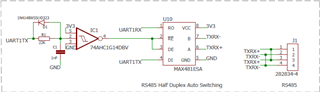
我已附上该示意图供参考。 这在我们之前的其他主板上也起了作用。 现在,为了测试问题,我已移除MAX481ESA并直接连接UART引脚,以确保芯片不会导致问题。
