This thread has been locked.

If you have a related question, please click the "Ask a related question" button in the top right corner. The newly created question will be automatically linked to this question.

[参考译文] TM4C123GH6PGE:如何以正确的方式设置引导加载程序和通信?

Guru**** 2390765 points
Other Parts Discussed in Thread: EK-TM4C123GXL, TM4C123GH6PGE

请注意,本文内容源自机器翻译,可能存在语法或其它翻译错误,仅供参考。如需获取准确内容,请参阅链接中的英语原文或自行翻译。

https://e2e.ti.com/support/microcontrollers/arm-based-microcontrollers-group/arm-based-microcontrollers/f/arm-based-microcontrollers-forum/1039227/tm4c123gh6pge-how-to-setup-the-bootloader-and-comms-the-right-way

器件型号:TM4C123GH6PGE
主题中讨论的其他器件: TM4C123EK-TM4C123GXL

我喜欢进入引导加载程序模式并进行固件更新。
到目前为止、我在执行同步时失败(发送0x55、0x55)


我编写了一个小的 python 脚本、该脚本尝试连接并执行 DFU。

2021-09-24 10:51:14.657 DEBUG:	open uart /dev/ttyUSB0
2021-09-24 10:51:14.658 DEBUG:	try to sync 0/100
...
2021-09-24 10:51:14.734 DEBUG:	try to sync 3/100
2021-09-24 10:51:14.742 DEBUG:	got response but value was 0x00
2021-09-24 10:51:14.742 DEBUG:	try to sync 4/100
2021-09-24 10:51:14.742 DEBUG:	got response but value was 0x33
...

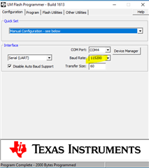
在我的固件上、我将 UART 设置为115200、8、N
一段时间后、我将通过引导加载程序模式

void tiva_bl_activateUART(void) {
	// stop systick
	sys_clock_disable();
	// disable all intr
	irq_lock();

	// start bootloader
	ROM_UpdateUART();
}

此代码在 Zephir 上运行、并使用 Zephir 内核 API 禁用 SysTick 和中断。
使用我的配置正在根据 Tiva hal(2.2.0295)进行编译

#define PART_TM4C123GH6PGE
#define TARGET_IS_TM4C123_RB1

有什么想法我错过了吗?

  • 请注意,本文内容源自机器翻译,可能存在语法或其它翻译错误,仅供参考。如需获取准确内容,请参阅链接中的英语原文或自行翻译。

    您好!

     您是否有机会运行 TivaWare 引导加载程序示例?

    引导加载程序位于:C:\ti\TivaWare_C_Series-2.2.0.295\examples\boards\ek-tm4c123gxl\boot_serial

    调用 ROM_UpdateUART 以跳回引导加载程序的应用示例可在  以下位置找到:C:\ti\TivaWare_C_Series-2.2.0.295\examples\boards\ek-tm4c123gxl\boot_demo_uart_rom

  • 请注意,本文内容源自机器翻译,可能存在语法或其它翻译错误,仅供参考。如需获取准确内容,请参阅链接中的英语原文或自行翻译。

    嗨、噢
    @运行引导加载程序的机会示例:
    我使用了"TivaWare_C_Series-2.2.0.295/examples/boards/ek-tm4c123gxl/boot_demo_uart_rom"作为模板。
    由于我的 UART 已经初始化、我不运行配置代码。 到目前为止、我的代码未使用"map_"前缀作为函数。

    @常规:
    我正在使用 Zephir ARM 工具链编译代码。 它基于 gcc。 makefile 由 Zephir 生成。 那么、采用您的示例代码意味着为我进行移植。 我喜欢避免这种情况。

    让我们首先检查我是否正确设置了 Tiva driverlib。
    您能否澄清一下我需要在哪里设置正确的定义(在头文件或编译器中)。 我将使用 TM4C123GH6PGE。 我需要定义的位置和内容、以便根据我的 MCU 正确编译驱动程序库。

    目前、我在没有任何编译器定义的情况下求解了它(仅通过预处理器):

    #ifndef SRC_DRV_CFG_TIVA_H_
    #define SRC_DRV_CFG_TIVA_H_
    
    #define PART_TM4C123GH6PGE
    #define TARGET_IS_TM4C123_RB1
    
    #include <tm4c123gh6pge.h>
    
    #include <hw_memmap.h>
    #include <pin_map.h>
    #include <gpio.h>
    #include <sysctl.h>
    #include <uart.h>
    #include <i2c.h>
    #include <can.h>
    #include <timer.h>
    #include <adc.h>
    #include <pwm.h>
    #include <rom.h>
    
    #endif /* SRC_DRV_CFG_TIVA_H_ */
    

  • 请注意,本文内容源自机器翻译,可能存在语法或其它翻译错误,仅供参考。如需获取准确内容,请参阅链接中的英语原文或自行翻译。

    您好!

     我看不到您的#include 头文件有问题。  

  • 请注意,本文内容源自机器翻译,可能存在语法或其它翻译错误,仅供参考。如需获取准确内容,请参阅链接中的英语原文或自行翻译。

    Thx 用于确认。

    我已仔细检查 UART 设置。 我的是相同的。 如前所述、如果我每隔100毫秒发送一次(0x55、0x55)、那么在6次发送 (0x00、0x33)回读后、我将得到。 改变我的笔记本电脑上的波特率会产生不同的模式。

    让我们尝试排除副作用。 在调用 UART 引导加载程序(通过 ROM_UpdateUART)之前、我已经设置了我的系统(PLL、GPIO、i2c、CAN、计时器、 ADC、UART)。 当我启动引导加载程序时、将启用所有外设。
    如示例所示-在启动引导加载程序之前、我将禁用所有 intr (和 SysTick)。 也许我缺少一些东西-我是否需要禁用所有外设等?

    请告诉我如何从正在运行的固件启动 ROM 引导加载程序?

  • 请注意,本文内容源自机器翻译,可能存在语法或其它翻译错误,仅供参考。如需获取准确内容,请参阅链接中的英语原文或自行翻译。

    我做了一些测试。

    禁用外设不起作用。

    我还直接从开始执行引导加载程序启动。 相同的0x5555 -> 0x0033模式

    我通过 ROM_VERSION = 0x26E (622)读取 ROM 版本是否可以确认我正在使用正确的 API?

  • 请注意,本文内容源自机器翻译,可能存在语法或其它翻译错误,仅供参考。如需获取准确内容,请参阅链接中的英语原文或自行翻译。
    [引用 userid="495727" URL"~/support/microcontrollers/arm-based-microcontrollers-group/arm-based-microcontrollers/f/arm-based-microcontrollers-forum/1039227/tm4c123gh6pge-how-to-setup-the-bootloader-and-comms-the-right-way/3845953 #3845953)]让我们尝试排除副作用。 在调用 UART 引导加载程序(通过 ROM_UpdateUART)之前、我已经设置了我的系统(PLL、GPIO、i2c、CAN、计时器、 ADC、UART)。 当我启动引导加载程序时、所有外设均已启用。

    您无需禁用这些外设。 但是、您必须禁用与它们相关的中断。 请参考 TivaWare 示例以禁用到 NVIC 的所有中断。 如果您已经禁用了如下所示的中断、那么您就可以了。 无需禁用外设。  

    //*****************************************************************************
    //
    // Passes control to the boot loader and initiates a remote software update.
    //
    // This function passes control to the boot loader and initiates an update of
    // the main application firmware image via UART0
    //
    // \return Never returns.
    //
    //*****************************************************************************
    void
    JumpToBootLoader(void)
    {
        //
        // Disable all processor interrupts.  Instead of disabling them
        // one at a time, a direct write to NVIC is done to disable all
        // peripheral interrupts.
        //
        HWREG(NVIC_DIS0) = 0xffffffff;
        HWREG(NVIC_DIS1) = 0xffffffff;
    
        //
        // Call the ROM UART boot loader.
        //
        ROM_UpdateUART();
    }

    您使用哪种工具下载代码? 我想您没有使用 LM 闪存编程器。 是这样吗? 您可以在 C:\ti\TivaWare_C_Series-2.2.0.295\tools\bin\sflash.exe 中尝试 sflash.exe 吗? 这是一个命令行工具、用于通过 UART 下载固件。  

    我的理解是、您没有使用库存 boot_serial 示例。 是这样吗? 您进行了一些修改。 您进行了哪些更改? 如果可能、您能否运行该示例以确保它在您的一侧正常工作。

  • 请注意,本文内容源自机器翻译,可能存在语法或其它翻译错误,仅供参考。如需获取准确内容,请参阅链接中的英语原文或自行翻译。

    在代码处、我添加了:

    	HWREG(NVIC_DIS0) = 0xffffffff;
    	HWREG(NVIC_DIS1) = 0xffffffff;
    	HWREG(NVIC_DIS2) = 0xffffffff;
    	HWREG(NVIC_DIS3) = 0xffffffff;
    	HWREG(NVIC_DIS4) = 0xffffffff;
    

    我直接或通过 openOCD 使用 JLink SWD

    我可以在 Ubuntu 上编译 sflash。 您希望查看哪些日志?

    我想使用 ROM 引导加载程序。 我的蓝图是"/boards/ek-tm4c123gxl/boot_demo_uart_rom

    它不起作用。

    我可以确认我的 UART 在我的固件上工作。 尽管 PCB 是预生产 PCB、但可能存在一些错误(不类似)

  • 请注意,本文内容源自机器翻译,可能存在语法或其它翻译错误,仅供参考。如需获取准确内容,请参阅链接中的英语原文或自行翻译。

    您好!

     我 多次运行库存 TivaWare 示例  boot_demo_uart_ROM、它始终对我有效。  boot_demo_uart_ROM 示例非常短。 您能否按原样运行? 只需将.out 或.bin 文件加载到闪存中、然后查看它是否首先起作用。  

  • 请注意,本文内容源自机器翻译,可能存在语法或其它翻译错误,仅供参考。如需获取准确内容,请参阅链接中的英语原文或自行翻译。

    我还使用 sflash.exe 下载代码、代码正在传递。  

  • 请注意,本文内容源自机器翻译,可能存在语法或其它翻译错误,仅供参考。如需获取准确内容,请参阅链接中的英语原文或自行翻译。

    请注意 、在 boot_demo_uart_ROM 示例中、必须按下 LaunchPad 上的 SW1开关、以便它将跳转到 ROM 引导加载程序。 查看我在 sflash.exe 命令行中使用的用于禁用自动波特的开关。  

  • 请注意,本文内容源自机器翻译,可能存在语法或其它翻译错误,仅供参考。如需获取准确内容,请参阅链接中的英语原文或自行翻译。

    已尝试在 Ubuntu 上编译 sflash、但失败

    stefan@stefan-ThinkPad-L13-Gen-2:~/Downloads/TivaWare_C_Series-2.2.0.295/tools/sflash$ make -j
      CC    packet_handler.c
      CC    sflash.c
      CC    uart_handler.c
    gcc: error: unrecognized command-line option ‘-mno-cygwin’; did you mean ‘-mno-clwb’?
    gcc: error: unrecognized command-line option ‘-mno-cygwin’; did you mean ‘-mno-clwb’?
    gcc: error: unrecognized command-line option ‘-mno-cygwin’; did you mean ‘-mno-clwb’?
    make: *** [../toolsdefs:99: sflash.o] Error 1
    make: *** Waiting for unfinished jobs....
    make: *** [../toolsdefs:99: packet_handler.o] Error 1
    

    我将快速尝试执行 该项目内的 boot_demo_uart_ROM 代码(ConfigureUART + JumpToBootLoader)。

    是否有控制 ROM 引导加载程序代码的外部信号?

  • 请注意,本文内容源自机器翻译,可能存在语法或其它翻译错误,仅供参考。如需获取准确内容,请参阅链接中的英语原文或自行翻译。

    您好!

    [引用 userid="495727" URL"~/support/microcontrollers/arm-based-microcontrollers-group/arm-based-microcontrollers/f/arm-based-microcontrollers-forum/1039227/tm4c123gh6pge-how-to-setup-the-bootloader-and-comms-the-right-way/3847377 #3847377"]是否有控制 ROM 引导加载程序代码的外部信号?[/quot]

      boot_demo_uart_rom 的 main() 非常简单。 它会切换 LED 并等待用户在调用 ROM UART 引导加载程序之前按 LaunchPad 上的 SW1 (PF4引脚)。 除此之外、没有其他信号控制 BOOT_DEMOD_UART_ROM 程序流。  

    //*****************************************************************************
    //
    // A simple application demonstrating the use of the ROM UART boot loader.
    //
    //*****************************************************************************
    int
    main(void)
    {
        //
        // Enable lazy stacking for interrupt handlers.  This allows floating-point
        // instructions to be used within interrupt handlers, but at the expense of
        // extra stack usage.
        //
        MAP_FPULazyStackingEnable();
    
        //
        // Set the system clock to run at 50MHz from the PLL.
        //
        MAP_SysCtlClockSet(SYSCTL_SYSDIV_4 | SYSCTL_USE_PLL | SYSCTL_XTAL_16MHZ |
                           SYSCTL_OSC_MAIN);
    
        //
        // Initialize the peripherals for the serial UART boot loader.
        //
        ConfigureUART();
    
        //
        // Initialize the buttons driver.
        //
        ButtonsInit();
    
        //
        // Enable the GPIO port that is used for the on-board LED.
        //
        MAP_SysCtlPeripheralEnable(SYSCTL_PERIPH_GPIOF);
    
        //
        // Enable the GPIO pin for the LED (PF3) as an output.
        //
        MAP_GPIOPinTypeGPIOOutput(GPIO_PORTF_BASE, GPIO_PIN_3);
    
        //
        // If the Switch SW1 is not pressed then blink the LED.  Press
        // and hold the SW1 for the debouncer to recognize the pin pressed.
        // On switch SW1 press detection, exit the blinking program and jump
        // to the ROM boot loader.
        //
        while ((ButtonsPoll(0, 0) & LEFT_BUTTON) == 0)
        {
            MAP_GPIOPinWrite(GPIO_PORTF_BASE, GPIO_PIN_3, GPIO_PIN_3);
            MAP_SysCtlDelay(SysCtlClockGet() / 50);
            MAP_GPIOPinWrite(GPIO_PORTF_BASE, GPIO_PIN_3, 0x00);
            MAP_SysCtlDelay(SysCtlClockGet() / 50);
        }
    
        //
        // Before passing control make sure that the LED is turned OFF.
        //
        MAP_GPIOPinWrite(GPIO_PORTF_BASE, GPIO_PIN_3, 0x00);
    
        //
        // Pass control to whichever flavor of boot loader the board is configured
        // with.
        //
        JumpToBootLoader();
    
        //
        // The boot loader should not return.  In the off chance that it does,
        // enter a dead loop.
        //
        while(1)
        {
        }
    }
    

  • 请注意,本文内容源自机器翻译,可能存在语法或其它翻译错误,仅供参考。如需获取准确内容,请参阅链接中的英语原文或自行翻译。

    我的意思是">ROM<<引导加载程序不是演示应用程序的代码;)我在调试器中看到,在调用"ROM_UpdateUART"后,指令指针会转到0x1000000以上的地址

  • 请注意,本文内容源自机器翻译,可能存在语法或其它翻译错误,仅供参考。如需获取准确内容,请参阅链接中的英语原文或自行翻译。

    ROM 存储器映射到0x01000000。 因此、正在发生到 ROM 的跳转。  

  • 请注意,本文内容源自机器翻译,可能存在语法或其它翻译错误,仅供参考。如需获取准确内容,请参阅链接中的英语原文或自行翻译。

    我想此时我们可以排除、引导加载程序未启动。 我还针对不同的波特率检查了引导加载程序。 同步无法正常工作。 与我的115200-8-N 配置类似 (笔记本电脑到 MCU (TX) 0x5555 -> MCU 到笔记本电脑(Rx) 0x0033)

    如前所述、我想检查对 ROM 引导加载程序有何影响。 您能给我提供建议还是给我一个介绍 ROM 引导加载程序的文档吗?

  • 请注意,本文内容源自机器翻译,可能存在语法或其它翻译错误,仅供参考。如需获取准确内容,请参阅链接中的英语原文或自行翻译。

    请注意、在我显示的屏幕截图中、我禁用了自动波特率检测。 为什么不尝试禁用自动波特率并尝试与我相同的设置、看看这是否会产生影响。 否则、我真的不知道您的工作为何、而它在我身边工作得非常完美。  

    下面是 sflash 使用指南。  

  • 请注意,本文内容源自机器翻译,可能存在语法或其它翻译错误,仅供参考。如需获取准确内容,请参阅链接中的英语原文或自行翻译。

    我的问题写得不好。

    我要求提供存储在 tm4c123gh6pe ROM 中的引导加载程序
    不适用于"sflash" CLI 工具

  • 请注意,本文内容源自机器翻译,可能存在语法或其它翻译错误,仅供参考。如需获取准确内容,请参阅链接中的英语原文或自行翻译。

    好的、ROM 用户指南是我们唯一拥有的内容。  

    https://www.ti.com/lit/pdf/spmu367

  • 请注意,本文内容源自机器翻译,可能存在语法或其它翻译错误,仅供参考。如需获取准确内容,请参阅链接中的英语原文或自行翻译。

    查看我找到的内容

    When an application calls back to the ROM-based boot loader to start an update over the UART
    port, the auto-baud feature is bypassed, along with UART configuration and pin configuration.

    这意味着我通过发送0x5555尝试的自动波特同步是错误的。 因此、我应该在之前使用 out sync (autobaud)直接对引导加载程序执行 ping 操作。

    是否有办法将 UART 外设复位回其复位默认值?

  • 请注意,本文内容源自机器翻译,可能存在语法或其它翻译错误,仅供参考。如需获取准确内容,请参阅链接中的英语原文或自行翻译。

    快速更新

    如果我现在使用(032020)对引导加载程序进行引脚化、则响应为00CC。 我确定 CC 是1类响应(ACK)、因为如果我把 ping 消息弄乱、我将收到 NACK (在这种情况下、我将使用0033)

    那么、现在的停留是:为什么我在1类响应之前每次都看到00?
    我的协议源为 SPMA074A

  • 请注意,本文内容源自机器翻译,可能存在语法或其它翻译错误,仅供参考。如需获取准确内容,请参阅链接中的英语原文或自行翻译。

    您好!

     正如我提到过的、我禁用自动波特率、它适用于我使用 LM 闪存编程器或 sflash.exe。 我不确定自动波特率是否起作用。 我需要从过去的论坛档案中进行一些研究。

  • 请注意,本文内容源自机器翻译,可能存在语法或其它翻译错误,仅供参考。如需获取准确内容,请参阅链接中的英语原文或自行翻译。

    尤里卡
    我丢弃从引导加载程序接收到的第一个 Rx 字节、现在我可以执行固件 DFU。
    下周我将做一些范围界定、并让您知道谁在生成 Rx 的零字节。

  • 请注意,本文内容源自机器翻译,可能存在语法或其它翻译错误,仅供参考。如需获取准确内容,请参阅链接中的英语原文或自行翻译。

    很高兴你取得了良好的进展。  

  • 请注意,本文内容源自机器翻译,可能存在语法或其它翻译错误,仅供参考。如需获取准确内容,请参阅链接中的英语原文或自行翻译。

    你好、

    我在 UART Rx/TX 上放置了一些频谱分析仪。 您可以清楚地看到、引导加载程序在 TX 之前添加了一个0x00。

    ping request with 0x00 before ACK

    每次引导加载程序发送一些字节时都会发生这种情况
    有什么想法、根本原因是什么?

    显示 SEND_DATA 消息的 ACK 的另一张图片
    send_data ack with leading 0x00

  • 请注意,本文内容源自机器翻译,可能存在语法或其它翻译错误,仅供参考。如需获取准确内容,请参阅链接中的英语原文或自行翻译。
    [引用 userid="495727" URL"~/support/microcontrollers/arm-based-microcontrollers-group/arm-based-microcontrollers/f/arm-based-microcontrollers-forum/1039227/tm4c123gh6pge-how-to-setup-the-bootloader-and-comms-the-right-way/3853673 #3853673"]您可以清楚地看到引导加载程序在 TX 之前添加了0x00

    请参阅源文件 BL_main.c 您可以看到,当 bootloader 接收到 command_pping 时,它将使用 AckPacket()进行回复。 请参阅下面的代码段。

            //
            // The first byte of the data buffer has the command and determines
            // the format of the rest of the bytes.
            //
            switch(g_pui8DataBuffer[0])
            {
                //
                // This was a simple ping command.
                //
                case COMMAND_PING:
                {
                    //
                    // This command always sets the status to COMMAND_RET_SUCCESS.
                    //
                    g_ui8Status = COMMAND_RET_SUCCESS;
    
                    //
                    // Just acknowledge that the command was received.
                    //
                    AckPacket();
    
                    //
                    // Go back and wait for a new command.
                    //
                    break;
                }
    

    现在看一下 BL_packet.c 文件,了解如何对 AckPacket()进行编码。  

    //*****************************************************************************
    //
    //! Sends an Acknowledge packet.
    //!
    //! This function is called to acknowledge that a packet has been received by
    //! the microcontroller.
    //!
    //! \return None.
    //
    //*****************************************************************************
    void
    AckPacket(void)
    {
        //
        // ACK/NAK packets are the only ones with no size.
        //
        SendData(g_pui8ACK, 2);
    }

    如您所见,AckPacket()将调用 SendData()来发送两个字节的数据。 引导加载程序发送的内容位于 g_pui8ACK 中。 现在看看 g_pui8ACK[2]是如何定义的。  

    //*****************************************************************************
    //
    // The packet that is sent to acknowledge a received packet.
    //
    //*****************************************************************************
    static const uint8_t g_pui8ACK[2] = { 0, COMMAND_ACK };

    您可以看到、这两个字节包含一个0x0、后跟 COMMAND_ACK。 在 bl_commands.h 文件中定义的 COMMAND_ACK 为0xCC、COMMAND_NAK 为0x33。  

    //*****************************************************************************
    //
    // This is the value that is sent to acknowledge a packet.
    //
    //*****************************************************************************
    #define COMMAND_ACK             0xcc
    
    //*****************************************************************************
    //
    // This is the value that is sent to not-acknowledge a packet.
    //
    //*****************************************************************************
    #define COMMAND_NAK             0x33

    我希望这一点现在已经清楚、为什么0x0会出现在0xCC 之前。  

  • 请注意,本文内容源自机器翻译,可能存在语法或其它翻译错误,仅供参考。如需获取准确内容,请参阅链接中的英语原文或自行翻译。

    非常好
    供参考如果您查看文档 SPMA074A 第7页(第2.3.3章响应数据包结构)、您将看到没有提到0x00。

    这个答案解决了我的问题。 Thx

  • 请注意,本文内容源自机器翻译,可能存在语法或其它翻译错误,仅供参考。如需获取准确内容,请参阅链接中的英语原文或自行翻译。

    您好 Stefan、

     我同意  SPMA074A 在说 ACK 只是一个字节时有点误导。 它是一个两字节数据包、其中 0x0作为起始字节、后跟引导加载程序源代码实现中的 ACK 字节(0x33)。