This thread has been locked.

If you have a related question, please click the "Ask a related question" button in the top right corner. The newly created question will be automatically linked to this question.

[参考译文] TM4C1230E6PM:微复位

Guru**** 2385390 points
请注意,本文内容源自机器翻译,可能存在语法或其它翻译错误,仅供参考。如需获取准确内容,请参阅链接中的英语原文或自行翻译。

https://e2e.ti.com/support/microcontrollers/arm-based-microcontrollers-group/arm-based-microcontrollers/f/arm-based-microcontrollers-forum/1164811/tm4c1230e6pm-reset-of-micro

器件型号:TM4C1230E6PM

您好!

我有多个系统通过 CANbus 进行通信。 微控制器使用 ADC、主 I2C、CANbus 和 SysTick。 所有 ms、发出 ADC 测量请求、每100ms、我读取 I2C 上的数据。 微控制器接收来自 CANbus 的请求并在调度程序的1ms 时基内重新响应。

只有一个系统可以在请求时重新响应,每个系统的 ID 都不同。

我有10个系统、在本周结束时、我有4个系统被复位。 (当我有复位时、我失去了微控制器的功率)。 我没有这个问题的计时器、但是我的客户安装了这个问题、在很多小时后会看到复位、但所有系统都不会被复位。

请求是否可能在微控制器中产生故障?

此致、

  • 请注意,本文内容源自机器翻译,可能存在语法或其它翻译错误,仅供参考。如需获取准确内容,请参阅链接中的英语原文或自行翻译。

    尊敬的 Micou:

    系统故障有许多可能的原因、您提供的说明并不足以说明可能发生的情况。 也就是说、我不认为只有简单的 CAN 请求才会在正常情况下导致软件复位。

    一种方法是最初尝试使用来调试、即查看 复位原因(RESC)寄存器以确定导致系统复位的原因。 这可能需要向启动例程添加额外的代码、以读取并保存结果、因为确切的复位时间不是很清楚。

    需要 注意的一个方面是应用中是否有任何外设被禁用的情况。 如果外设被禁用、并且应用的另一部分不知道并尝试访问外设、那么仅此一项就会导致系统故障。

    另一种可能是内存问题、例如堆栈溢出或缓冲区溢出。 这也可能触发意外的系统复位、原因与代码中的哪一部分提示溢出(可能包括 CAN 请求)有关。

    如果您遇到可以复制复位的情况、并且这是系统中的软件故障、则下一个关键步骤是参考我们的故障调试指南 :https://www.ti.com/lit/pdf/spma043 -尽管考虑到复位的随机性、我认为这当前并不适用。 只是想提前提供、以便您了解该文档。

    这些是让您开始调试工作的一些初始想法、当您了解更多详细信息时、请告诉我、以便我可以进一步指导您如何调试此问题。

    此致、

    Ralph Jacobi

  • 请注意,本文内容源自机器翻译,可能存在语法或其它翻译错误,仅供参考。如需获取准确内容,请参阅链接中的英语原文或自行翻译。

    您好 Jacobi、

    我错误地按下了"已解决"按钮。

    RESC 寄存器不提供状态、我有一个外部看门狗、当电源电压低于2.63V 时、该看门狗会生成外部复位。 我已经测试了这个寄存器、并且在我重新启动系统时、除了外部复位之外、我没有其他值。

    我今天晚上测试了一个软、当我转到 Harfault 处理程序时、他向 EEPROM FaultStatus 寄存器、HFaultStatus 寄存器写入数据。 但是、当我重新启动电池时、读取 EEPROM 中的数据、读取0x00000000以进行寄存器读取。

    我在24h 测试了一组系统、其中10个系统在没有 CANbus 的情况下处于活动状态、并且没有出现问题

    我在 CANbus 和2个系统停止时再次尝试。 第一个、工作4小时40后、第二个、工作12小时后。

    此致、

    Ludovic Micou

  • 请注意,本文内容源自机器翻译,可能存在语法或其它翻译错误,仅供参考。如需获取准确内容,请参阅链接中的英语原文或自行翻译。

    您好!

    在测试故障记录后、我在代码中看到一个错误、导致不记录该记录。 因此、我将使用该校正重复我的测试。 我在代码中注意到、当 CANBUS 被禁用时、CANBus 可能会中断  

    此致、

    Ludovic Micou

  • 请注意,本文内容源自机器翻译,可能存在语法或其它翻译错误,仅供参考。如需获取准确内容,请参阅链接中的英语原文或自行翻译。

    尊敬的 Micou:

    [引用 userid="89705" URL"~/support/microcontrollers/arm-based-microcontrollers-group/arm-based-microcontrollers/f/arm-based-microcontrollers-forum/1164811/tm4c1230e6pm-reset-of-micro/4382464 #4382464">测试故障记录后,我在代码中看到一个错误,导致不记录该记录。 因此、我将使用该校正重复我的测试。 我在代码中注意到、当 CANBUS 处于停用状态时、CANBus 可能会中断 

    感谢此处的更新、请告诉我这方面的结果。 您描述的代码肯定会触发故障情况、因此希望解决后您的问题能够得到解决。

    不用担心错误的解决方案按钮-我将继续监控该主题、直到我们同意您的问题得到完全解决。

    此致、

    Ralph Jacobi

  • 请注意,本文内容源自机器翻译,可能存在语法或其它翻译错误,仅供参考。如需获取准确内容,请参阅链接中的英语原文或自行翻译。

    您好 Jacobi、

    我在 FAULTSTAT 中有一个错误、其值为0x20000 (INVSTAT)。 我在软中不使用 EPSR 寄存器。 我在 MMAdress 寄存器中有数据0xE000ED34、在寄存器 BusAdress 寄存器中有数据0xE000ED38。

     是否可以在 TI 的 CANbus 库中调用 EPSR 寄存器?

    此故障的可能原因是什么?

    此致、

    Ludovic Micou

  • 请注意,本文内容源自机器翻译,可能存在语法或其它翻译错误,仅供参考。如需获取准确内容,请参阅链接中的英语原文或自行翻译。

    您好 Jacobi、

    我删除了优化并将堆栈增加到1024。 运行超过12小时后、我没有恢复复位。

    我只对 CAN 有问题。 在只有一个系统中、我在 CANBUS 中失去通信。 如果我检测到错误、或者在5秒内未检测到回执的时间、我应该重新注入 CANbus。

    中断 CAN:

    /**
     * @fn void vd_app_scheduler_Update(void)
     * @brief Update scheduler counter and variable
     * @param none
     * @return none
     */
    void CAN0_Handler(void)
    {
    uint32_t ui32Status;
    
         //
         // Read the CAN interrupt status to find the cause of the interrupt
         //
         ui32Status = CANIntStatus(CAN0_BASE, CAN_INT_STS_CAUSE);
    
         //
         // If the cause is a controller status interrupt, then get the status
         //
         if(ui32Status == CAN_INT_INTID_STATUS)
         {
             //
             // Read the controller status.  This will return a field of status
             // error bits that can indicate various errors.  Error processing
             // is not done in this example for simplicity.  Refer to the
             // API documentation for details about the error status bits.
             // The act of reading this status will clear the interrupt.  If the
             // CAN peripheral is not connected to a CAN bus with other CAN devices
             // present, then errors will occur and will be indicated in the
             // controller status.
             //
             ui32Status = CANStatusGet(CAN0_BASE, CAN_STS_CONTROL);
    
             //
             // Set a flag to indicate some errors may have occurred.
             //
    
             if (ui32Status & 0x08)
             {
                 g_bMsgObj3Sent = 1;
                 g_bMsgObj4Sent = 1;
             }
    
             if (ui32Status & 0x10)
             {
                 u8_FlagRx = 1;
             }
    
             CANIntClear(CAN0_BASE, 0);
             CANIntClear(CAN0_BASE, 1);
             CANIntClear(CAN0_BASE, 2);
             CANIntClear(CAN0_BASE, 3);
             CANIntClear(CAN0_BASE, 4);
             if (ui32Status & 0xE3)
             {
                 vd_srv_COM_Init();
                 u8_FlagErrorCan = 1;
                 g_bErrFlag = 1;
    
             }
    
         }
    
         //
         // Check if the cause is message object 1, which is used for sending
         // message 1.
         //
         else if(ui32Status == 1)
         {
             u8_FlagRx = 1;
    
             //
             // Getting to this point means that the TX interrupt occurred on
             // message object 1, and the message TX is complete.  Clear the
             // message object interrupt.
             //
             CANIntClear(CAN0_BASE, 1);
    
             //
             // Increment a counter to keep track of how many messages have been
             // sent.  In a real application this could be used to set flags to
             // indicate when a message is sent.
             //
             g_ui32Msg1Count++;
    
             //
             // Since the message was sent, clear any error flags.
             //
             g_bErrFlag = 0;
         }
    
         //
         // Check if the cause is message object 2, which is used for sending
         // message 2.
         //
         else if(ui32Status == 2)
         {
             u8_FlagRx = 1;
    
             //
             // Getting to this point means that the TX interrupt occurred on
             // message object 1, and the message TX is complete.  Clear the
             // message object interrupt.
             //
             CANIntClear(CAN0_BASE, 2);
    
             //
             // Increment a counter to keep track of how many messages have been
             // sent.  In a real application this could be used to set flags to
             // indicate when a message is sent.
             //
             g_ui32Msg1Count++;
    
             //
             // Since the message was sent, clear any error flags.
             //
             g_bErrFlag = 0;
         }
    
         //
         // Check if the cause is message object 3, which is used for sending
         // messages 3 and 4.
         //
         else if(ui32Status == 3)
         {
             u8_FlagRx = 1;
    
             //
             // Getting to this point means that the TX interrupt occurred on
             // message object 1, and the message TX is complete.  Clear the
             // message object interrupt.
             //
             CANIntClear(CAN0_BASE, 3);
    
             //
             // Increment a counter to keep track of how many messages have been
             // sent.  In a real application this could be used to set flags to
             // indicate when a message is sent.
             //
             g_ui32Msg1Count++;
    
             //
             // Since the message was sent, clear any error flags.
             //
             g_bErrFlag = 0;
         }
    
         //
         // Otherwise, something unexpected caused the interrupt.  This should
         // never happen.
         //
         else if(ui32Status == 4)
         {
             CANIntClear(CAN0_BASE, 4);
    
             //
             // Increment a counter to keep track of how many messages have been
             // sent.  In a real application this could be used to set flags to
             // indicate when a message is sent.
             //
             g_ui32Msg1Count++;
             g_bMsgObj3Sent = 1;
             g_bMsgObj4Sent = 1;
             //
             // Since the message was sent, clear any error flags.
             //
             g_bErrFlag = 0;
         }
         else
         {
             g_bMsgObj3Sent = 1;
             g_bMsgObj4Sent = 1;
             vd_srv_COM_Init();
             u8_FlagErrorCan = 1;
         }
    
    }

    初始化 CAN  

    void vd_srv_COM_Init(void)
    {
        u32_UiCanBus = CAN0_BASE;
        /* Enable Rx interrupt */
        CANDisable(u32_UiCanBus);
        CANIntDisable(u32_UiCanBus, CAN_INT_MASTER | CAN_INT_ERROR | CAN_INT_STATUS);
    
        IntDisable(INT_CAN0);
        CANInit(u32_UiCanBus);
        CANBitRateSet(u32_UiCanBus, SysCtlClockGet(), 250000);
        CANIntEnable(u32_UiCanBus, CAN_INT_MASTER | CAN_INT_ERROR | CAN_INT_STATUS);
        IntEnable(INT_CAN0);
        IntPrioritySet(INT_CAN0, 10);
    
        CANEnable(u32_UiCanBus);
        g_sCANMsgObjectRx1.ui32Flags = (MSG_OBJ_RX_INT_ENABLE | MSG_OBJ_USE_ID_FILTER
                                     );
        g_sCANMsgObjectRx1.pui8MsgData = u8_CanRxData;
        g_sCANMsgObjectRx1.ui32MsgID = 0x20;
        g_sCANMsgObjectRx1.ui32MsgIDMask = 0;
        g_sCANMsgObjectRx1.ui32Flags = (MSG_OBJ_RX_INT_ENABLE | MSG_OBJ_USE_ID_FILTER
                                 );
        g_sCANMsgObjectRx1.ui32MsgLen = 8;
        CANMessageSet(u32_UiCanBus, 1, &g_sCANMsgObjectRx1, MSG_OBJ_TYPE_RX);
        g_sCANMsgObjectRx1.ui32MsgLen = 7;
        CANMessageSet(u32_UiCanBus, 2, &g_sCANMsgObjectRx1, MSG_OBJ_TYPE_RX);
        g_sCANMsgObjectRx1.ui32MsgLen = 8;
        g_sCANMsgObjectRx1.ui32Flags = (MSG_OBJ_RX_INT_ENABLE | MSG_OBJ_USE_ID_FILTER | MSG_OBJ_REMOTE_FRAME
                                     );
        CANMessageSet(u32_UiCanBus, 3, &g_sCANMsgObjectRx1, MSG_OBJ_TYPE_RX_REMOTE);
    }

    在执行所有 ms 的调度程序中:  

    void vd_srv_COM_ReceptInt(uint32_t lu32_UiCanBus)
    {
        /* Get RX message */
        if (u8_FlagRx == 1)
        {
            CANMessageGet(lu32_UiCanBus, 1, &g_sCANMsgObjectRx1, 0);
            u8_FlagRx = 0;
            vd_srv_com_ReadCan(lu32_UiCanBus);
        }
        else
        {
            u32_TempoReinitCan++;
            if (u32_TempoReinitCan > 5000UL)
            {
                vd_srv_COM_Init();
                u32_TempoReinitCan = 0UL;
            }
        }
        if (u8_FlagErrorCan == 1)
        {
           // vd_srv_COM_Init();
             u32_TempoReinitCan = 0UL;
            u8_FlagErrorCan = 0;
        }
      
    }

    什么会导致我失去通信和复位无法正常工作?

    此致

    Ludovic Micou

  • 请注意,本文内容源自机器翻译,可能存在语法或其它翻译错误,仅供参考。如需获取准确内容,请参阅链接中的英语原文或自行翻译。

    尊敬的 Micou:

    [引用 userid="89705" URL"~/support/microcontrollers/arm-based-microcontrollers-group/arm-based-microcontrollers/f/arm-based-microcontrollers-forum/1164811/tm4c1230e6pm-reset-of-micro/4383785 #4383785"]我在 MMAdress 寄存器中具有数据0xE000ED34和寄存器 Busress 中具有数据0xE000ED38。[/quot]

    这并不是很容易加起来的、因为这些是这些寄存器的地址。 我认为您可能没有正确阅读内容。

    [引用 userid="89705" URL"~/support/microcontrollers/arm-based-microcontrollers-group/arm-based-microcontrollers/f/arm-based-microcontrollers-forum/1164811/tm4c1230e6pm-reset-of-micro/4383785 #4383785"] 是否可以在 TI 的 CANbus 库中调用 EPSR 寄存器?

    EPSR 是执行程序状态寄存器、因此无需在库中进行调用、但 Cortex-M4F 会在执行应用程序代码时始终如一地使用该调用。

    您可以在故障处理程序中检查 EPSR 寄存器以获取堆栈式 PSR 的当前值、这有助于了解触发故障的操作。

    [引用 userid="89705" URL"~/support/microcontrollers/arm-based-microcontrollers-group/arm-based-microcontrollers/f/arm-based-microcontrollers-forum/1164811/tm4c1230e6pm-reset-of-micro/4385475 #4385475)]我删除了优化并将堆栈增加到1024。 运行超过12小时后、我没有恢复复位。[/报价]

    我不是100%清楚您的意思是"id not recover a reset"-这是否意味着代码现在正在执行而不会出现问题?

    如果是这样、我会增大堆栈、这是更重要的更改。 您应该重新进行优化并重新测试、看看这是否解决了问题。

    您还可以检查堆栈溢出。 如果您想执行此操作、您可以执行以下步骤。

    要测试堆栈溢出、应执行以下步骤:

    1. 在 Debug 文件夹内的.map 文件中标识栈的起始存储器位置
    2. 进入调试模式、但不开始运行代码
    3. 转至“View”(查看)à“Memory Browser”(内存浏览器)
    4. 在输入框中输入堆栈的地址
      1. 在上面的示例中、该地址为0x0000420c (您需要在其前面添加0x!)
    5. 这将向您显示堆栈内容
    6. 接下来、使用已知数据填充堆栈内容:
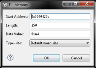
      1. 转至“Tools”(工具)à“Fill Memory”(填充内存)
      2. 输入起始地址=.map 文件的栈地址
      3. length =栈大小/2 (在我的示例中为500、因此500/2 = 250)–这是因为每个存储器位置存储栈的2个字节
      4. 数据值= 0xAA (或0x55、或其他易于识别的值)
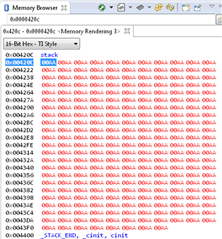
    7. 内存浏览器现在应如下所示:
    8. 由于堆栈已被完全覆盖、在运行代码前恢复初始堆栈设置非常重要。 这可以通过以下两种方式之一来实现:
      1. 使用“软重置”
      2. 退出调试模式并重新进入调试模式
        1. 我必须对某些项目执行此操作、但通常软复位会起作用
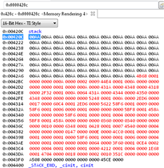
      3. 正确完成后、存储器浏览器应在栈顶或底端具有非0xAA 字节:
    9. 现在、根据应用程序运行代码足够长的时间
      1. 如果发生溢出、所有输入的数据(我的示例中为0xAA)将不再位于栈中

    请注意、我的示例适用于略有不同的 MCU、但相同的原理适用于 TM4C。 对于 TM4C .map 文件、您会看到以下内容:

    此致、

    Ralph Jacobi