

请注意,本文内容源自机器翻译,可能存在语法或其它翻译错误,仅供参考。如需获取准确内容,请参阅链接中的英语原文或自行翻译。
器件型号:TM4C123GE6PM 您好!
按照 Ralph Jacobi 在本帖子中提供的有关通过 UART 打印浮点编号的帮助:
我编写了以下代码:
//////////////////////////////////////////////////////////////////////////////////////////////////////////////////////////////////////////////////////////////////////////////////////////////////////////////////////////////////////////////////////////////////////
#include
#include
#include "driverlib/debug.h"
#include "driverlib/gpio.h"
#include "driverlib/pin_map.h"
#include "driverlib/pwm.h"
#include "driverlib/rom.h"
#include "driverlib/sysctl.h"
#include "inc/hw_gpio.h"
#include "#include "包含"hw_map.h"#include "#include
#include //使用 NULL 指针
#define PWM_FREQUENCY 55
//////////////////////////////////////////////////////////////////////////////////////////////////////////////////////////////////////////////////////////////////////////////////////////////////////////////////////////////////////////////////////////////////////
//我的 I2C 定义并包括
#include "driverlib/i2c.h"
#include "driverlib/interrv.h"
#include "inc/hw_i2c.h"
#include
"sensorlib/i2cm_drv.h"
#include "sensorlib/mpu6050.h"////
/////////////////////////////////////////////////////////////#////#//////////////////////////#//////////////////////////#///////////////////////////////////////////
//我的 UART 定义并包括
#include "driverlib/uartstdio.h"
#include "utils/uartstdio.h"
//////////////////////////////////////////////////////////////////////////////////////////////////////////////////////////////////////////////////////////////////////////////////////////////////
#include "definitions _mpu6050.h"
tI2CMInstance g_sI2CInst;// I2C 主驱动程序结构。 "tI2CMInstance"是在 i2cm_drv.h 文件中定义的。
tMPU6050 g_sMPU6050Inst;// MPU6050传感器驱动程序结构。 "tMPU6050"在 mpu6050.h 文件中定义。
volatile unsigned long g_vui8DataFlag;//数据就绪标志
volatile unsigned long g_vui8ErrorFlag;//错误标志
void
ISL29023I2CIntHandler (void)
{
I2CMIntHandler (&g_sI2CInst);
}
////////////////////////////////////////////////////////////////////////////////////////////////////////////////////////////////////////////////////////////////////////////////////////////////////////////////////////////////////////////////////////
int main (void)
{
fAccel[3]、fGyro[3]={0.0};
uint8_t register_mpu6050_o_pwr_mgmt_1;//用于调试
uint8_t register_mpu6050_o_卫生 组织_am_i;//用于调试
uint8_t 索引= 0;
uint32_t 计数器= 0;
int32_t i32IntegerPart = 0;
int32_t i32FractionPart = 0;
//配置时钟
SysCtlClockSet (SYSCTL_SYSDIV_5|SYSCTL_USE_PLL|SYSCTAL_16MHz|SYSCTL_OSC_MAIN);
//////////////////////////////////////////////////////////////////////////////////////////////////////////////////////////////////////////////////////////////////////////////////////////////////
//我的 I2C 初始化代码
//启用包含 I2C 2的 GPIO 外设
SysCtlPeripheralEnable (SYSCTL_Periph_GPIOE);
//启用 I2C 模块2
SysCtlPeripheralEnable (SYSCTL_Periph_I2C2);
//为端口 E4和 E5上的 I2C2功能配置引脚多路复用。
GPIOPinConfigure (GPIO_PE4_I2C2SCL);
GPIOPinConfigure (GPIO_PE5_I2C2SDA);
//为这些引脚选择 I2C 功能。
GPIOPinTypeI2CSCL (GPIO_Porte _BASE、GPIO_PIN_4);
GPIOPinTypeI2C (GPIO_Porte _BASE、GPIO_PIN_5);
IntMasterEnable();
// USER_I2CMInit (&G) sI2CInst、I2C2_base、INT_I2C2、0xFF、 0xFF、SysCtlClockGet ();//将 SCL 设置为100KHz 而不是原始400kHz。
I2CMInit (&g_sI2CInst、I2C2_base、INT_I2C2、0xFF、0xFF、 SysCtlClockGet ();
SysCtlDelay (SysCtlClockGet ()/3);
//如果使用该变量的函数成功,USER_MPU6050Callback 会将 g_BMPU6050Done 变量修改为 true。
//初始化 MPU6050
G_bMPU6050Done = false;
MPU6050Init (&g_sMPU6050Inst、&g_sI2CInst、MPU6050_I2C_ADDRESS、USER_MPU6050Callback、0);
while (!g_bMPU6050Done){}
G_bMPU6050Done = false;
// SysCtlDelay (SysCtlClockGet ()/ 3);
G_bMPU6050Done = false;
MPU6050Read (&g_sMPU6050Inst、MPU6050_O_WH_AM_I、®ister_mpu6050_o_WH_AM_I、1、USER_MPU6050Callback、0);
while (!g_bMPU6050Done){}
G_bMPU6050Done = false;
SysCtlDelay (SysCtlClockGet ()/3);
G_bMPU6050Done = false;
MPU6050Read (&g_sMPU6050Inst、MPU6050_O_PWR_Mgmt_1、®ister_mpu6050_o_pwr_mgmt_1、1、USER_MPU6050Callback、0); //有人忘记将设备从睡眠状态中取出。
while (!g_bMPU6050Done){}
G_bMPU6050Done = false;
SysCtlDelay (SysCtlClockGet ()/3);
G_bMPU6050Done = false;
//写入0x00会将器件从睡眠状态唤醒。
//写入0x01会将器件从睡眠状态唤醒、并使主时钟 PLL 具有 X 轴陀螺仪参考。
// MPU6050Write (&g_sMPU6050Inst、MPU6050_O_PWR_Mgmt_1、0x00、1、USER_MPU6050Callback、 0);
MPU6050Write (&g_sMPU6050Inst、MPU6050_O_PWR_Mgmt_1、0x01、1、USER_MPU6050Callback、 0);
while (!g_bMPU6050Done){}
G_bMPU6050Done = false;
SysCtlDelay (SysCtlClockGet ()/3);
G_bMPU6050Done = false;
MPU6050Read (&g_sMPU6050Inst、MPU6050_O_PWR_Mgmt_1、®ister_mpu6050_o_pwr_mgmt_1、1、USER_MPU6050Callback、0);
while (!g_bMPU6050Done){}
G_bMPU6050Done = false;
SysCtlDelay (SysCtlClockGet ()/3);
G_bMPU6050Done = false;
//将 MPU6050配置为+/- 4 g 加速计范围。
// MPU6050ReadModifyWrite (&G) sMPU6050Inst、MPU6050_O_ACCEL_CONFIG、~MPU6050_ACCEL_CONFIG_AFS_SEL_M、MPU6050_ACCEL_CONFIG_AFS_SEL_4G、USER_MPU6050Callback、 0);
MPU6050ReadModifyWrite (&G) sMPU6050Inst、MPU6050_O_ACCEL_CONFIG、~MPU6050_ACCEL_CONFIG_AFS_SEL_M、MPU6050_ACCEL_CONFIG_AFS_SEL_2G、USER_MPU6050Callback、 0);
while (!g_bMPU6050Done){}
G_bMPU6050Done = false;
SysCtlDelay (SysCtlClockGet ()/ 3);
////////////////////////////////////////////////////////////////////////////////////////////////////////////////////////////////////////////////////////////////////////////////////////////////////////////////////////////////////////////////////////////////////////
//我的 UART 初始化代码
SysCtlPeripheralEnable (SYSCTL_Periph_UART0);
SysCtlPeripheralEnable (SYSCTL_Periph_GPIOA);
GPIOPinConfigure (GPIO_PA0_U0RX);
GPIOPinConfigure (GPIO_PA1_U0TX);
GPIOPinTypeUART (GPIO_Porta_base、GPIO_PIN_0 | GPIO_PIN_1);
UARTClockSourceSet (UART0_BASE、UART_CLOCK_PIOSC);
UARTStdioConfig (0、115200、16000000);
UARTprintf (" UART 工作工具");
////////////////////////////////////////////////////////////////////////////////////////////////////////////////////////////////////////////////////////////////////////////////////////////////////////////////////////////////////////////////////////////////////////
while (1)
{
G_bMPU6050Done = false;
while (计数器< 1000000)
{
计数器++;
}
计数器= 0;
//获取新的加速计和陀螺仪读数。
// MPU6050DataAccelGetFloat (&g_sMPU6050Inst、&fAccel[0]、&fAccel[1]、&fAccel[2]);
// MPU6050DataGyroGetFloat (&G) sMPU6050Inst、&fGyro[0]、&fGyro[1]、&fGyro[2]);
SAMPLE_accumulation_average
(
&g_sMPU6050Inst、
256 、
加速 、
fGyro
) ;
浮点角= atan2 (fAccel[0]、fAccel[2])*(180.0/ PI);
i32IntegerPart =(int32_t)角度;
i32FractionPart =(int32_t)(angle * 1000.0f);
i32FractionPart = i32FractionPart -(i32IntegerPart * 1000);
UARTprintf ("角度:%3d.%03d\t\n"、i32IntegerPart、i32FractionPart);
//将浮点转换为整数并通过 UART 发送
对于(index = 0;index <= 2;index ++)
{
i32IntegerPart =(int32_t) fAccel[index];
i32FractionPart =(int32_t)(fAccel[index]* 1000.0f);
i32FractionPart = i32FractionPart -(i32IntegerPart * 1000);
if (i32FractionPart < 0)
{
i32FractionPart *=-1;
}
如果(索引=0)
{
UARTprintf ("加速计 X:%3d.%03d\t\n"、i32IntegerPart、i32FractionPart);
}
如果(索引==1)
{
UARTprintf ("加速计 Y:%3d.%03d\t\n"、i32IntegerPart、i32FractionPart);
}
如果(索引==2)
{
UARTprintf ("加速计 Z:%3d.%03d\t\n"、i32IntegerPart、i32FractionPart);
}
}
对于(index = 0;index <= 2;index ++)
{
i32IntegerPart =(int32_t) fGyro[索引];
i32FractionPart =(int32_t)(fGyro[index]* 1000.0f);
i32FractionPart = i32FractionPart -(i32IntegerPart * 1000);
if (i32FractionPart < 0)
{
i32FractionPart *=-1;
}
如果(索引=0)
{
UARTprintf ("Gyro X:%3d.%03d\t\n"、i32IntegerPart、i32FractionPart);
}
如果(索引==1)
{
UARTprintf ("Gyro Y:%3d.%03d\t\n"、i32IntegerPart、i32FractionPart);
}
如果(索引==2)
{
UARTprintf ("陀螺仪 Z:%3d.%03d\t\n\n\n\n\n"、i32IntegerPart、i32FractionPart);
}
}
/*
我们感兴趣的是:
X 轴上的加速计读数(垂直于扫描床)。
Y 轴(滚珠轴承轴)中的陀螺仪读数。
*
fAccel[0]= 0.0;
fAccel[1]= 0.0;
fAccel[2]= 0.0;
fGyro[0]= 0.0;
fGyro[1]=0.0;
fGyro[2]= 0.0;
}
}
一切都很好-除了事情、
当"angle"值为负值时-(-)符号的打印效果不好(随附屏幕截图)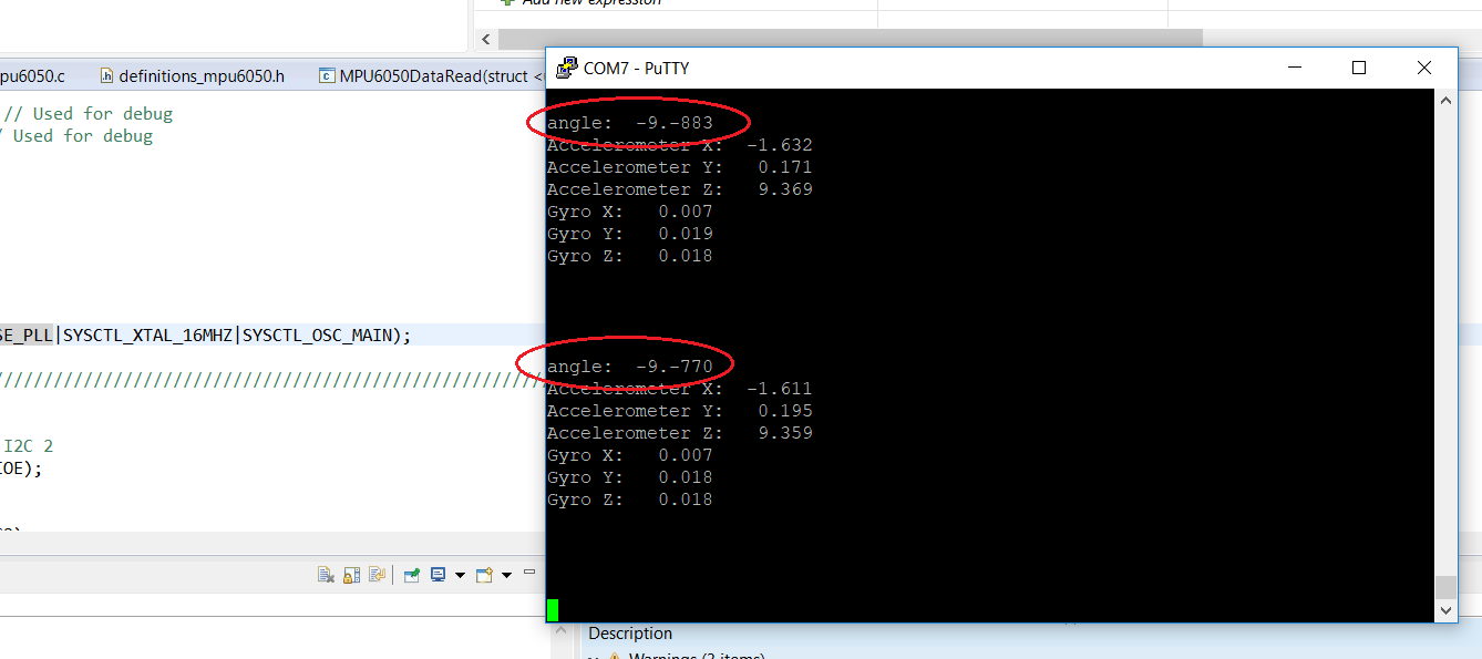
请帮助我修复代码。
