This thread has been locked.

If you have a related question, please click the "Ask a related question" button in the top right corner. The newly created question will be automatically linked to this question.

[参考译文] TM4C1292NCPDT:将 PWM 发生器模块偏移180度

Guru**** 2386620 points
请注意,本文内容源自机器翻译,可能存在语法或其它翻译错误,仅供参考。如需获取准确内容,请参阅链接中的英语原文或自行翻译。

https://e2e.ti.com/support/microcontrollers/arm-based-microcontrollers-group/arm-based-microcontrollers/f/arm-based-microcontrollers-forum/1219897/tm4c1292ncpdt-offsetting-pwm-generator-blocks-by-180-degrees

器件型号:TM4C1292NCPDT

我们有一个使用 TM4C1292NCPDT的定制电路板。  

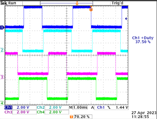
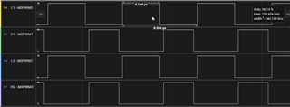
该板将使用两个交错式 PWM 信号对。 目前、我以向上/向下模式运行 PWM 第0代和 PWM 第1代。 是否可以使用 TISW API 来偏移发生器模块使其180度相位差? 例如、在下图中、我希望 L1和 L2具有180度的相位差、H1和 H2具有180度的相位差、同时保持相同的占空比。 软件 API 中是否有方法可以设置其中一个生成器的起始计数来实现该目的? 占空比会在运行时发生变化、因此需要是真正的180度相移(而不是反转50%占空比信号)。

这是相应的初始化代码:

#define GENERATOR_PERIOD_COUNTS 1000
#define DEAD_BAND_DURATION_COUNTS 50

SysCtlPeripheralEnable(SYSCTL_PERIPH_GPIOF);
while(!SysCtlPeripheralReady(SYSCTL_PERIPH_GPIOF));

// Configure the GPIO for PWM peripheral use.
GPIOPinConfigure(GPIO_PF0_M0PWM0);
GPIOPinConfigure(GPIO_PF1_M0PWM1);
GPIOPinConfigure(GPIO_PF2_M0PWM2);
GPIOPinConfigure(GPIO_PF3_M0PWM3);
GPIOPinTypePWM(GPIO_PORTF_BASE, GPIO_PIN_0);
GPIOPinTypePWM(GPIO_PORTF_BASE, GPIO_PIN_1);
GPIOPinTypePWM(GPIO_PORTF_BASE, GPIO_PIN_2);
GPIOPinTypePWM(GPIO_PORTF_BASE, GPIO_PIN_3);

SysCtlPeripheralEnable(SYSCTL_PERIPH_PWM0);         // enable the pwm peripheral
while(!SysCtlPeripheralReady(SYSCTL_PERIPH_PWM0));  // wait for the peripheral to be ready
PWMClockSet(PWM0_BASE, PWM_SYSCLK_DIV_1);           // Sets the PWM clock configuration to use the system clock with a divider of 1

/*
 * Configure generator blocks to run in up/down mode which allows
 * use of the built-in dead band time. In this mode, the synchronization of
 * the 2 signals in each generator are synchronized by default, so we
 * don't need to set any.
 */
PWMGenConfigure(PWM0_BASE, PWM_GEN_0, PWM_GEN_MODE_UP_DOWN | PWM_GEN_MODE_NO_SYNC);
PWMGenConfigure(PWM0_BASE, PWM_GEN_1, PWM_GEN_MODE_UP_DOWN | PWM_GEN_MODE_NO_SYNC);

/*
 * Set the PWM period. Configures the reference counter that counts in up/down mode.
 *
 * f = PWM_ref_clk / N ... where f is the desired frequency, N is the passed param,
 * and PWM_ref_clk is the reference clock.
 */
PWMGenPeriodSet(PWM0_BASE, PWM_GEN_0, GENERATOR_PERIOD_COUNTS);
PWMGenPeriodSet(PWM0_BASE, PWM_GEN_1, GENERATOR_PERIOD_COUNTS);

/*
 * Enables dead band generation with a configurable buffer on both the rising and falling
 * edge of the signals. Enabling this will automatically synchronize the signal pairs in
 * each of the generator blocks.
 */
PWMDeadBandEnable(PWM0_BASE, PWM_GEN_0, DEAD_BAND_DURATION_COUNTS, DEAD_BAND_DURATION_COUNTS);
PWMDeadBandEnable(PWM0_BASE, PWM_GEN_1, DEAD_BAND_DURATION_COUNTS, DEAD_BAND_DURATION_COUNTS);

PWMPulseWidthSet(PWM0_BASE, PWM_OUT_0, 550); // complement signal PWM_OUT_1 updates automatically
PWMPulseWidthSet(PWM0_BASE, PWM_OUT_2, 550); // complement signal PWM_OUT_3 updates automatically

PWMGenEnable(PWM0_BASE, PWM_GEN_0);
PWMGenEnable(PWM0_BASE, PWM_GEN_1);

PWMSyncTimeBase(PWM0_BASE, PWM_GEN_1_BIT | PWM_GEN_0_BIT);

PWMOutputState(PWM0_BASE, PWM_OUT_2_BIT | PWM_OUT_3_BIT | PWM_OUT_0_BIT | PWM_OUT_1_BIT, true);

  • 请注意,本文内容源自机器翻译,可能存在语法或其它翻译错误,仅供参考。如需获取准确内容,请参阅链接中的英语原文或自行翻译。

    您好!

     您可以反转 L2和 H2以使它们与 L1和 H1异相180。  

  • 请注意,本文内容源自机器翻译,可能存在语法或其它翻译错误,仅供参考。如需获取准确内容,请参阅链接中的英语原文或自行翻译。

    这不也交换占空比吗? 因此、如果 L1的占空比为40%、则 L2的反相占空比将为60%。 我希望两者都具有40%的占空比、但 L2只需要在半个周期后发生。

  • 请注意,本文内容源自机器翻译,可能存在语法或其它翻译错误,仅供参考。如需获取准确内容,请参阅链接中的英语原文或自行翻译。

    当我摆弄反转函数时、它看起来像是在正确地抵消信号;然而、它并没有正确地考虑死区。 就好像我需要在负死区中写入一样。 实际上、可以将输入的死区添加到上升沿和下降沿、而不是减去它。 因此、我能够获得的最佳结果是零死区、这是一个问题。 我需要一些保证,这些 L2和 H2不会是高在同一时间. 是否可以通过某种方法对反相信号应用负死区?

  • 请注意,本文内容源自机器翻译,可能存在语法或其它翻译错误,仅供参考。如需获取准确内容,请参阅链接中的英语原文或自行翻译。

    您好!

     我想您应该能够同步 GEN0与 Gen1、并在 L1和 L2之间创建相位关系。  

    同步。 PWM 发生器和它的两个输出信号与结合使用
    其他 PWM 发生器使用通用的统一时基。 多个 PWM 发生器
    使用相同的计数器加载值进行配置、同步可用于保证这一点
    它们还具有相同的计数值(PWM 发生器必须在此之前进行配置
    同步)。 通过该功能、可以使用一个已知的信号产生两个以上的 MnPWMn 信号
    因为计数器总是具有相同的关系
    试验。 该模块中的其他状态提供了维护共用时基和的机制
    相互同步。

  • 请注意,本文内容源自机器翻译,可能存在语法或其它翻译错误,仅供参考。如需获取准确内容,请参阅链接中的英语原文或自行翻译。

    您好!

     是否仍需要有关设置180度异相 PWM 的帮助? TivaWare API 本身不支持它。 您必须绕过 API 才能实现这一点。 我能够获得两对死区信号、并且两对彼此之间具有180度的相位差。 请参见下方的。  


    我修改库存示例 pwm_dead_band.c  

    //*****************************************************************************
    //
    // pwm_dead_band.c - Example demonstrating the PWM dead-band generator.
    //
    // Copyright (c) 2019-2020 Texas Instruments Incorporated.  All rights reserved.
    // Software License Agreement
    // 
    // Texas Instruments (TI) is supplying this software for use solely and
    // exclusively on TI's microcontroller products. The software is owned by
    // TI and/or its suppliers, and is protected under applicable copyright
    // laws. You may not combine this software with "viral" open-source
    // software in order to form a larger program.
    // 
    // THIS SOFTWARE IS PROVIDED "AS IS" AND WITH ALL FAULTS.
    // NO WARRANTIES, WHETHER EXPRESS, IMPLIED OR STATUTORY, INCLUDING, BUT
    // NOT LIMITED TO, IMPLIED WARRANTIES OF MERCHANTABILITY AND FITNESS FOR
    // A PARTICULAR PURPOSE APPLY TO THIS SOFTWARE. TI SHALL NOT, UNDER ANY
    // CIRCUMSTANCES, BE LIABLE FOR SPECIAL, INCIDENTAL, OR CONSEQUENTIAL
    // DAMAGES, FOR ANY REASON WHATSOEVER.
    // 
    // This is part of revision 2.2.0.295 of the EK-TM4C1294XL Firmware Package.
    //
    //*****************************************************************************
    
    #include <stdbool.h>
    #include <stdint.h>
    #include "inc/hw_types.h"
    #include "inc/hw_memmap.h"
    #include "inc/hw_pwm.h"
    
    #include "driverlib/debug.h"
    #include "driverlib/gpio.h"
    #include "driverlib/pin_map.h"
    #include "driverlib/pwm.h"
    #include "driverlib/rom.h"
    #include "driverlib/rom_map.h"
    #include "driverlib/sysctl.h"
    #include "driverlib/uart.h"
    #include "utils/uartstdio.h"
    
    //*****************************************************************************
    //
    //! \addtogroup pwm_examples_list
    //! <h1>PWM Dead-band Generator Demo (pwm_dead_band)</h1>
    //!
    //! The example configures the PWM0 block to generate a 25% duty cycle signal
    //! on PF2 with dead-band generation.  This will produce a complement of PF2 on
    //! PF3 (75% duty cycle).  The dead-band generator is set to have a 10us delay
    //! on the rising and falling edges of the PF2 PWM signal.
    //!
    //! This example uses the following peripherals and I/O signals.
    //! - GPIO Port F peripheral (for PWM pins)
    //! - M0PWM2 - PF2
    //! - M0PWM3 - PF3
    //!
    //! UART0, connected to the Virtual Serial Port and running at 115,200, 8-N-1,
    //! is used to display messages from this application.
    //
    //*****************************************************************************
    
    //*****************************************************************************
    //
    // The variable g_ui32SysClock contains the system clock frequency in Hz.
    //
    //*****************************************************************************
    uint32_t g_ui32SysClock;
    
    //*****************************************************************************
    //
    // The error routine that is called if the driver library encounters an error.
    //
    //*****************************************************************************
    #ifdef DEBUG
    void
    __error__(char *pcFilename, uint32_t ui32Line)
    {
    }
    #endif
    
    //*****************************************************************************
    //
    // Configure the UART and its pins.  This must be called before UARTprintf().
    //
    //*****************************************************************************
    void
    ConfigureUART(void)
    {
        //
        // Enable the GPIO Peripheral used by the UART.
        //
        MAP_SysCtlPeripheralEnable(SYSCTL_PERIPH_GPIOA);
    
        //
        // Enable UART0.
        //
        MAP_SysCtlPeripheralEnable(SYSCTL_PERIPH_UART0);
    
        //
        // Configure GPIO Pins for UART mode.
        //
        MAP_GPIOPinConfigure(GPIO_PA0_U0RX);
        MAP_GPIOPinConfigure(GPIO_PA1_U0TX);
        MAP_GPIOPinTypeUART(GPIO_PORTA_BASE, GPIO_PIN_0 | GPIO_PIN_1);
    
        //
        // Initialize the UART for console I/O.
        //
        UARTStdioConfig(0, 115200, g_ui32SysClock);
    }
    
    //*****************************************************************************
    //
    // Configure PWM for dead-band generation.
    //
    //*****************************************************************************
    
    #define PWM1GENA_OFFSET 0xA0
    #define PWM2GENA_OFFSET 0xE0
    #define PWM1GENB_OFFSET 0xA4
    #define PWM2GENB_OFFSET 0xE4
    #define PWM1CMPA_OFFSET 0x98
    #define PWM1CMPB_OFFSET 0x9C
    #define PWM2CMPA_OFFSET 0xD8
    #define PWM2CMPB_OFFSET 0xDC
    
    int
    main(void)
    {
        uint32_t ui32PWMClockRate;
    
        //
        // Run from the PLL at 120 MHz.
        // Note: SYSCTL_CFG_VCO_240 is a new setting provided in TivaWare 2.2.x and
        // later to better reflect the actual VCO speed due to SYSCTL#22.
        //
        g_ui32SysClock = MAP_SysCtlClockFreqSet((SYSCTL_XTAL_25MHZ |
                                                 SYSCTL_OSC_MAIN |
                                                 SYSCTL_USE_PLL |
                                                 SYSCTL_CFG_VCO_240), 120000000);
    
        //
        // Initialize the UART.
        //
        ConfigureUART();
    
        //
        // Display the setup on the console.
        //
        UARTprintf("PWM ->\n");
        UARTprintf("  Module: PWM0\n");
        UARTprintf("  Pin(s): PF2 and PF3\n");
        UARTprintf("  Features: Dead-band Generation\n");
        UARTprintf("  Duty Cycle: 25%% on PF2 and 75%% on PF3\n");
        UARTprintf("  Dead-band Length: 250 cycles\n\n");
    
        //
        // Enable the GPIO port that is used for the on-board LED.
        //
        MAP_SysCtlPeripheralEnable(SYSCTL_PERIPH_GPION);
    
        //
        // Enable the GPIO pin for the LED (PN0) as an output.
        //
        MAP_GPIOPinTypeGPIOOutput(GPIO_PORTN_BASE, GPIO_PIN_0);
    
        //
        // The PWM peripheral must be enabled for use.
        //
        MAP_SysCtlPeripheralEnable(SYSCTL_PERIPH_PWM0);
    
        //
        // Enable the GPIO port that is used for the PWM output.
        //
        MAP_SysCtlPeripheralEnable(SYSCTL_PERIPH_GPIOF);
    
        //
        // Enable the GPIO port that is used for the PWM output.
        //
        MAP_SysCtlPeripheralEnable(SYSCTL_PERIPH_GPIOG);
    
    
        //
        // Configure the GPIO pad for PWM function on pins PF2 and PF3.
        //
        MAP_GPIOPinConfigure(GPIO_PF2_M0PWM2);
        MAP_GPIOPinConfigure(GPIO_PF3_M0PWM3);
        MAP_GPIOPinTypePWM(GPIO_PORTF_BASE, GPIO_PIN_2);
        MAP_GPIOPinTypePWM(GPIO_PORTF_BASE, GPIO_PIN_3);
    
        //
        // Configure the GPIO pad for PWM function on pins PF2 and PF3.
        //
        MAP_GPIOPinConfigure(GPIO_PG0_M0PWM4);
        MAP_GPIOPinConfigure(GPIO_PG1_M0PWM5);
        MAP_GPIOPinTypePWM(GPIO_PORTG_BASE, GPIO_PIN_0);
        MAP_GPIOPinTypePWM(GPIO_PORTG_BASE, GPIO_PIN_1);
    
        //
        // Set the PWM clock to be SysClk / 8.
        //
        MAP_PWMClockSet(PWM0_BASE, PWM_SYSCLK_DIV_8);
    
        //
        // Use a local variable to store the PWM clock rate which will be
        // 120 MHz / 8 = 15 MHz. This variable will be used to set the
        // PWM generator period.
        //
        ui32PWMClockRate = g_ui32SysClock / 8;
    
        //
        // Configure PWM2 to count up/down with synchronization.
    
        MAP_PWMGenConfigure(PWM0_BASE, PWM_GEN_1,
                            PWM_GEN_MODE_UP_DOWN | PWM_GEN_MODE_SYNC);
    
        MAP_PWMGenConfigure(PWM0_BASE, PWM_GEN_2,
                            PWM_GEN_MODE_UP_DOWN | PWM_GEN_MODE_SYNC);
    
        // For PWM1GENA, set pin high when counter is zero and reset pin to low
        // when CMPA is matched during count up.
    
        HWREG(PWM0_BASE + PWM1GENA_OFFSET) = 0x0;
        HWREG(PWM0_BASE + PWM1GENA_OFFSET) = 0x023;
    
        // For PWM2GENA, set pin high when counter is reloaded and reset pin to low
        // when CMPA is matched during count down.
    
        HWREG(PWM0_BASE + PWM2GENA_OFFSET) = 0x0;
        HWREG(PWM0_BASE + PWM2GENA_OFFSET) = 0x4C;
    
        //
        // Set the PWM period to 250Hz.  To calculate the appropriate parameter
        // use the following equation: N = (1 / f) * PWMClk.  Where N is the
        // function parameter, f is the desired frequency, and PWMClk is the
        // PWM clock frequency based on the system clock.
        //
        MAP_PWMGenPeriodSet(PWM0_BASE, PWM_GEN_1, (ui32PWMClockRate / 250));
    
        MAP_PWMGenPeriodSet(PWM0_BASE, PWM_GEN_2, (ui32PWMClockRate / 250));
    
        //
        // Set PWM1 CMPA to 40% of half period during count up
        // Set PWM2 CMPA to 10% of half period during count down
        //
    
        HWREG(PWM0_BASE + PWM1CMPA_OFFSET) = MAP_PWMGenPeriodGet(PWM0_BASE, PWM_GEN_1) * 0.4;
        HWREG(PWM0_BASE + PWM2CMPA_OFFSET) = MAP_PWMGenPeriodGet(PWM0_BASE, PWM_GEN_2) * 0.1;
    
        PWMSyncUpdate(PWM0_BASE, PWM_GEN_1_BIT | PWM_GEN_2_BIT);
        //
        // Enable the dead-band generation on the PWM0 output signal.
        // These signals will have a 100us gap between the
        // rising and falling edges.
        // For this example the PWM clock rate is 15 MHz, so we will use
        // 150 cycles (1500 cycles / 15MHz = 100us) on both the rising and falling
        // edges of PF2.  Reference the datasheet for more information on PWM
        // dead-band generation.
        //
        MAP_PWMDeadBandEnable(PWM0_BASE, PWM_GEN_1, 1500, 1500);
        MAP_PWMDeadBandEnable(PWM0_BASE, PWM_GEN_2, 1500, 1500);
    
        //
        // Enable the PWM Out Bit 2 (PF2) and Bit 3 (PF3) output signals.
        //
        MAP_PWMOutputState(PWM0_BASE, PWM_OUT_2_BIT | PWM_OUT_3_BIT, true);
        MAP_PWMOutputState(PWM0_BASE, PWM_OUT_4_BIT | PWM_OUT_5_BIT, true);
    
        //
        // Enable the PWM generator block.
        //
        MAP_PWMGenEnable(PWM0_BASE, PWM_GEN_1);
        MAP_PWMGenEnable(PWM0_BASE, PWM_GEN_2);
    
    
        //
        // Loop forever blinking an LED while the PWM signals are generated.
        //
        while(1)
        {
            //
            // Turn on the LED.
            //
            MAP_GPIOPinWrite(GPIO_PORTN_BASE, GPIO_PIN_0, GPIO_PIN_0);
    
            //
            // This function provides a means of generating a constant length
            // delay.  The function delay (in cycles) = 3 * parameter.  Delay
            // 0.5 seconds arbitrarily.
            //
            MAP_SysCtlDelay((g_ui32SysClock / 2) / 3);
    
            //
            // Turn off the LED.
            //
            MAP_GPIOPinWrite(GPIO_PORTN_BASE, GPIO_PIN_0, 0x00);
    
            //
            // This function provides a means of generating a constant length
            // delay.  The function delay (in cycles) = 3 * parameter.  Delay
            // 0.5 seconds arbitrarily.
            //
            MAP_SysCtlDelay((g_ui32SysClock / 2) / 3);
        }
    }