This thread has been locked.

If you have a related question, please click the "Ask a related question" button in the top right corner. The newly created question will be automatically linked to this question.

[参考译文] TM4C129EKCPDT:I2C ACK/NACK 问题

Guru**** 661510 points
Other Parts Discussed in Thread: TMP1075
请注意,本文内容源自机器翻译,可能存在语法或其它翻译错误,仅供参考。如需获取准确内容,请参阅链接中的英语原文或自行翻译。

https://e2e.ti.com/support/microcontrollers/arm-based-microcontrollers-group/arm-based-microcontrollers/f/arm-based-microcontrollers-forum/1234308/tm4c129ekcpdt-i2c-ack-nack-issue

器件型号:TM4C129EKCPDT
主题中讨论的其他器件:TMP1075

您好、专家!

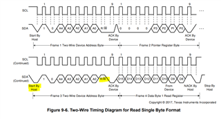
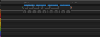
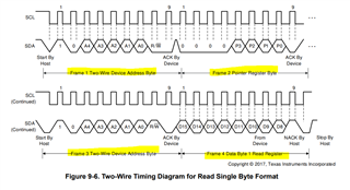
I2C ACK/NACK 面临一些问题。我们在 i2c 线路中发送3个字节、但仅发送两个字节:
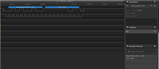
缺少第二个字节。

MAP_I2CMasterDataPut(I2C2_BASE, 0x00); //0x10
MAP_I2CMasterControl(I2C2_BASE, I2C_MASTER_CMD_BURST_SEND_START);
while(MAP_I2CMasterBusy(I2C2_BASE));
// while(!(MAP_I2CSlaveStatus(I2C2_BASE) & I2C_SLAVE_ACT_RREQ_FBR))
{

}
MAP_I2CMasterDataPut(I2C2_BASE, Dpot_Resistance_Todecimal); // value N
MAP_I2CMasterControl(I2C2_BASE, I2C_MASTER_CMD_BURST_SEND_FINISH); //I2C_MASTER_CMD_BURST_SEND_CONT
while(MAP_I2CMasterBusy(I2C2_BASE));

void init_i2c_init(void)
{
MAP_SysCtlPeripheralDisable(SYSCTL_PERIPH_I2C2);
MAP_SysCtlPeripheralReset(SYSCTL_PERIPH_I2C2);
MAP_SysCtlPeripheralEnable(SYSCTL_PERIPH_I2C2);
MAP_SysCtlPeripheralEnable(SYSCTL_PERIPH_GPIOL); //system enable gpio port L
MAP_SysCtlPeripheralEnable(SYSCTL_PERIPH_I2C2); // I2C2 system enable
MAP_GPIOPinConfigure(GPIO_PL1_I2C2SCL); //I2C2 clk gpio config port PL1
MAP_GPIOPinConfigure(GPIO_PL0_I2C2SDA); //I2C2 data PORT PL0
MAP_GPIOPinTypeI2C(GPIO_PORTL_BASE, GPIO_PIN_0); // PL0 is data
MAP_GPIOPinTypeI2CSCL(GPIO_PORTL_BASE,GPIO_PIN_1); // PL1 is clock
while(!MAP_SysCtlPeripheralReady(SYSCTL_PERIPH_I2C2)) // I2C2 peripheral ready
{

}
MAP_I2CMasterInitExpClk(I2C2_BASE, ui32SysClock, true); // I2C2 clock setup //false = 100KHZ ,true = 400khz
// MAP_I2CMasterSlaveAddrSet(I2C2_BASE, 0x29, false); /
MAP_I2CMasterSlaveAddrSet(I2C2_BASE, 0x29, false); // I2C2 address setup for write to slave
MAP_I2CMasterEnable(I2C2_BASE);

}


{

}

I2C 字节:82、0253
82 (0x29)是从器件的地址、它没有发送0 (零)。
只是发送82和253,为什么?
我是不是在犯一些错误?

***

谢谢你。

此致、
阿奇·A·阿奇

  • 请注意,本文内容源自机器翻译,可能存在语法或其它翻译错误,仅供参考。如需获取准确内容,请参阅链接中的英语原文或自行翻译。

    您好!

     请在以下行的每个地方更改、

    发件人:

    while (MAP_I2CMasterBusy (I2C2_base));

    至:

    while (!MAP_I2CMasterBusy (I2C2_base))// 在 while  (MAP_I2CMasterBusy (I2C2_base))的所有位置之前添加此行

    while (MAP_I2CMasterBusy (I2C2_base));

  • 请注意,本文内容源自机器翻译,可能存在语法或其它翻译错误,仅供参考。如需获取准确内容,请参阅链接中的英语原文或自行翻译。

    谢谢、Charles。

    您的帮助和建议可以解决这个问题。
    但现在我们从 i2c 从器件读取两个字节时遇到另一个问题、无法从从从器件获取任何数据。
    我们正在将 TMP1075NDRLR 用于 TI、请查找附加的屏幕快照。
    //读取
    {
    MAP_I2CMasterDataPut (I2C2_base、0x00);
    MAP_I2CMasterControl (I2C2_BASE、I2C_MASTER_CMD_BURST_RECEIVE_START);
    while (!MAP_I2CMasterBusy (I2C2_base))
    {


    while (MAP_I2CMasterBusy (I2C2_base));
    board_temp =MAP_I2CMasterDataGet (I2C2_base);
    while (!MAP_I2CMasterBusy (I2C2_base))
    {


    while (MAP_I2CMasterBusy (I2C2_base));
    board_temp =MAP_I2CMasterDataGet (I2C2_base);
    while (!MAP_I2CMasterBusy (I2C2_base))
    {


    while (MAP_I2CMasterBusy (I2C2_base));
    MAP_I2CMasterControl (I2C2_BASE、I2C_MASTER_CMD_BURST_RECEIVE_FINISH);

    此致、
    阿奇·A·阿奇

  • 请注意,本文内容源自机器翻译,可能存在语法或其它翻译错误,仅供参考。如需获取准确内容,请参阅链接中的英语原文或自行翻译。

    您好、Archie。

     我不熟悉  TMP1075NDRLR 、但您读取的 I2C 波形是否符合  TMP1075NDRLR 数据表中显示的波形。

    在您的代码中、我没有看到您从从从地址字节开始。 第一行从  将数据写入 TX 缓冲区的 MAP_I2CMasterDataPut (I2C2_base、0x00)开始。 它的作用是什么? 您在哪里启动用于读取的从地址字节、如上面的时序图中所示?

    下面是 I2C 器件的读数示例。  

    void
    I2CReadCommand(uint32_t * pui32DataRx)
    {
        //
        // Modify the data direction to true, so that seeing the address will
        // indicate that the I2C Master is initiating a read from the slave.
        //
        MAP_I2CMasterSlaveAddrSet(I2C7_BASE, SHT21_I2C_ADDRESS, true);
    
        //
        // Setup for first read.  Use I2C_MASTER_CMD_BURST_RECEIVE_START
        // to start a burst mode read.  The I2C master continues to own
        // the bus at the end of this transaction.
        //
        MAP_I2CMasterControl(I2C7_BASE, I2C_MASTER_CMD_BURST_RECEIVE_START);
    
        //
        // Wait until master module is done transferring.
        // The I2C module has a delay in setting the Busy flag in the register so
        // there needs to be a delay before checking the Busy bit.  The below loops
        // wait until the Busy flag is set, and then wait until it is cleared to
        // indicate that the transaction is complete.  This can take up to 633 CPU
        // cycles @ 100 kbit I2C Baud Rate and 120 MHz System Clock.  Therefore, a
        // while loop is used instead of SysCtlDelay.
        //
        while(!MAP_I2CMasterBusy(I2C7_BASE))
        {
        }
        while(MAP_I2CMasterBusy(I2C7_BASE))
        {
        }
    
        //
        // Read the first byte data from the slave.
        //
        pui32DataRx[0] = MAP_I2CMasterDataGet(I2C7_BASE);
    
        //
        // Setup for the second read.  Use I2C_MASTER_CMD_BURST_RECEIVE_CONT
        // to continue the burst mode read.  The I2C master continues to own
        // the bus at the end of this transaction.
        //
        MAP_I2CMasterControl(I2C7_BASE, I2C_MASTER_CMD_BURST_RECEIVE_CONT);
    
        //
        // Wait until master module is done transferring.
        //
        while(!MAP_I2CMasterBusy(I2C7_BASE))
        {
        }
        while(MAP_I2CMasterBusy(I2C7_BASE))
        {
        }
    
        //
        // Read the second byte data from the slave.
        //
        pui32DataRx[1] = MAP_I2CMasterDataGet(I2C7_BASE);
    
        //
        // Setup for the third read.  Use I2C_MASTER_CMD_BURST_RECEIVE_FINISH
        // to terminate the I2C transaction.  At the end of this transaction,
        // the STOP bit will be issued and the I2C bus is returned to the
        // Idle state.
        //
        MAP_I2CMasterControl(I2C7_BASE, I2C_MASTER_CMD_BURST_RECEIVE_FINISH);
    
        //
        // Wait until master module is done transferring.
        //
        while(!MAP_I2CMasterBusy(I2C7_BASE))
        {
        }
        while(MAP_I2CMasterBusy(I2C7_BASE))
        {
        }
        
        //
        // Note the third 8-bit data is the checksum byte.  It will be
        // left to the users as an exercise if they want to verify if the
        // checksum is correct.
        pui32DataRx[2] = MAP_I2CMasterDataGet(I2C7_BASE);
    }

  • 请注意,本文内容源自机器翻译,可能存在语法或其它翻译错误,仅供参考。如需获取准确内容,请参阅链接中的英语原文或自行翻译。

    谢谢、Charles。

    用于 i2c 初始化和 salve 地址设置
    void temp_sensor (void)
    {
    MAP_SysCtlPeripheralDisable (SYSCTL_Periph_I2C2);
    MAP_SysCtlPeripheralReset (SYSCTL_Periph_I2C2);
    MAP_SysCtlPeripheralEnable (SYSCTL_Periph_I2C2);
    MAP_SysCtlPeripheralEnable (SYSCTL_Periph_GPILL);
    MAP_SysCtlPeripheralEnable (SYSCTL_Periph_I2C2);
    MAP_GPIOPinConfigure (GPIO_PL1_I2C2SCL);
    MAP_GPIOPinConfigure (GPIO_PL0_I2C2SDA);//I2C2数据端口 PL0
    MAP_GPIOPinTypeI2C (GPIO_PORTL_BASE、GPIO_PIN_0);// PL0是数据
    MAP_GPIOPinTypeI2CSCL (GPIO_PORTL_BASE、GPIO_PIN_1);// PL1为时钟
    while (!MAP_SysCtl_Periph_I2C2)// I2C2外设就绪
    {

    MAP_I2CMasterInitExpClk (I2C2_base、ui32SysClock、true);// I2C2时钟设置
    MAP_I2CMasterSlaveAddrSet (I2C2_base、0x48、true);//从属设备的 I2C2地址设置
    MAP_I2CMasterEnable (I2C2_base);

    读取从器件。
    void read_temperature ()
    {
    uint32_t Board_temp[4];
    MAP_I2CMasterDataPut (I2C2_base、0x00);//SLAVE 寄存器
    MAP_I2CMasterControl (I2C2_BASE、I2C_MASTER_CMD_BURST_RECEIVE_START);
    while (!MAP_I2CMasterBusy (I2C2_base))
    {


    while (MAP_I2CMasterBusy (I2C2_base))
    {


    board_temp[0]= MAP_I2CMasterDataGet (I2C2_base);
    MAP_I2CMasterControl (I2C2_BASE、I2C_MASTER_CMD_BURST_RECEIVE_CONT);
    while (!MAP_I2CMasterBusy (I2C2_base))
    {


    while (MAP_I2CMasterBusy (I2C2_base))
    {


    board_temp[1]= MAP_I2CMasterDataGet (I2C2_base);
    MAP_I2CMasterControl (I2C2_BASE、I2C_MASTER_CMD_BURST_RECEIVE_FINISH);
    while (!MAP_I2CMasterBusy (I2C2_base))
    {


    while (MAP_I2CMasterBusy (I2C2_base));
    System_printf ("Btemp=%d %d"、Board_temp[0]、Board_temp[1]);System_flush ();

    第一个字节(0x91)为从器件地址
    第二个字节应为(0x00)、是从器件寄存器
    第三个字节应为温度的第一个字节
    第四个字节应为温度的第二个字节

    但我错了
    请找到随附的文件。

    此致、
    阿奇/苏米特

  • 请注意,本文内容源自机器翻译,可能存在语法或其它翻译错误,仅供参考。如需获取准确内容,请参阅链接中的英语原文或自行翻译。

    我认为您的波形不符合 TMP1075数据表中指定的读取序列。 查看下面的波形、了解从传感器读取一个字节的数据。 为了进行读取、您需要提供第一个帧、其中是用于写入方向的从器件地址字节。 第二帧是指定要读取的寄存器。 在第三帧中、您需要再次为读取方向提供一个从器件地址字节。 第四个帧是传感器器件返回的数据。 在您的波形中、我没有看到前两个帧。 我只能看到您从第3帧开始、然后再进行三次读取。 您能展示前两帧吗?  

  • 请注意,本文内容源自机器翻译,可能存在语法或其它翻译错误,仅供参考。如需获取准确内容,请参阅链接中的英语原文或自行翻译。

    感谢您的大力支持、Charles。

    客户确认现在工作正常。

    此致、
    阿奇·A·阿奇

  • 请注意,本文内容源自机器翻译,可能存在语法或其它翻译错误,仅供参考。如需获取准确内容,请参阅链接中的英语原文或自行翻译。

    Archie、

     感谢您发送编修。 很高兴问题得到解决。