请注意,本文内容源自机器翻译,可能存在语法或其它翻译错误,仅供参考。如需获取准确内容,请参阅链接中的英语原文或自行翻译。
器件型号:MSP432E401Y 主题中讨论的其他器件: SysConfig
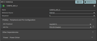
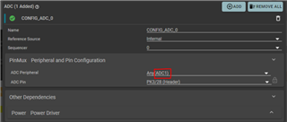
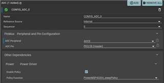
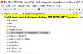
我有一个 MSP432E401Y FreeRTOS 项目、该项目使用4个不同的 ADC 通道。 其中一个 ADC (PK3)监视电位计的抽头。 无论电位器的实际状态如何、从该 ADC 读取的值似乎每隔几秒偶尔从1.8V 跳到3.3V。 我已经用示波器和电压表探测了电路板。 我已验证引脚21 (PK3)已用非常精密的探头连接到电位计、并且我的仪器读取了正确的电压。 其他 ADC 的工作非常出色、精度很高。 有人知道这可能是什么原因吗?