请注意,本文内容源自机器翻译,可能存在语法或其它翻译错误,仅供参考。如需获取准确内容,请参阅链接中的英语原文或自行翻译。
器件型号:TM4C129ENCPDT 主题中讨论的其他器件:EK-TM4C123GXL、 LAUNCHXL-CC2640R2、 EK-TM4C129EXL、 TM4C123GH6PM、
工具与软件:
您好、专家!
你好!
我是代表客户发布此帖子。 他们 从 TI 购买了三款开发板:EK-TM4C123GXL、EK-TM4C129EXL 和 LaunchxL-CC2640R2。 目前、他们正在从事一些项目、需要一些支持。
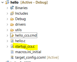
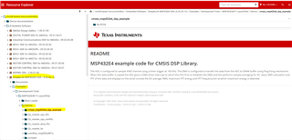
他们正在尝试在 Code Composer Studio (Linux)中为 TM4C129ENCPDT 和 TM4C123GH6PM 编写驱动程序。 他们一直在使用 Tivaware 驱动程序、并愿意尝试使用 CMSIS。
他们无法获取 CMSIS-Core 器件文件(由芯片供应商-德州仪器(TI)提供)。
请建议开始使用相同的工具。 我认为选择 Code Composer Studio 已经足够好了。
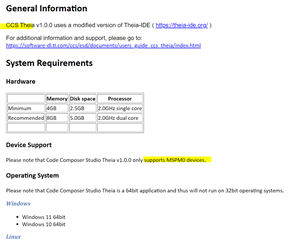
TI 最近与 Theia IDE 合作。 他们应该切换到 Theia、任何其他 IDE 或任何其他工具链吗?
此致、
乔纳森