This thread has been locked.

If you have a related question, please click the "Ask a related question" button in the top right corner. The newly created question will be automatically linked to this question.

[参考译文] TAS2770EVM:用户指南原理图似乎已过时

Guru**** 2652575 points

Other Parts Discussed in Thread: TAS2770EVM

请注意,本文内容源自机器翻译,可能存在语法或其它翻译错误,仅供参考。如需获取准确内容,请参阅链接中的英语原文或自行翻译。

https://e2e.ti.com/support/audio-group/audio/f/audio-forum/1589567/tas2770evm-user-guide-schematic-seems-out-of-date

器件型号: TAS2770EVM

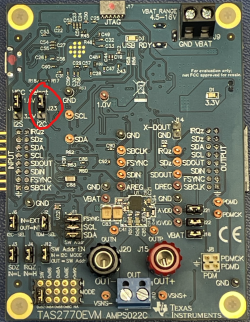
我最近购买的 TAS2770EVM 似乎与用户指南图 5 中的电路板图像或原理图不匹配。  例如、J23(在下图的顶部用红色圈出)不在用户指南末尾的图片、原理图或 BOM 中。  

image.png

此外、U25 和 U27 不在原理图中(可能是 Ref DES 更改了?)、请参阅下面圈出的:

image.png


我想要在 1.8V 模式下运行器件(我的 SOM 只有 1.8V IO) 并)并想知道 J23 处的 I2C 1.8V 配置跳线是如何工作的、所以我对这些元件很感兴趣。