This thread has been locked.

If you have a related question, please click the "Ask a related question" button in the top right corner. The newly created question will be automatically linked to this question.

[参考译文] TLV320AIC3262:将 TLV320AIC3262配置为主模式

Guru**** 2379970 points
Other Parts Discussed in Thread: TLV320AIC3262
请注意,本文内容源自机器翻译,可能存在语法或其它翻译错误,仅供参考。如需获取准确内容,请参阅链接中的英语原文或自行翻译。

https://e2e.ti.com/support/audio-group/audio/f/audio-forum/1197090/tlv320aic3262-configuration-of-tlv320aic3262-as-master-mode

器件型号:TLV320AIC3262

您好!  

我们将为我们的平台使用 tlv320aic3262编解码器。 我们希望将 TLV 编解码器作为主器件、将 I2S 作为从器件、

如下所述、我们要求对 Linux 内核进行设备树更改

 Sound0:sound0{
        兼容="简单音频卡";
        simple-audi-Card, name ="tlv320aic3262-hif";
        simple-audio 卡、格式="I2S";
        simple-audio-card、bitclock-master =<&sound_master>;
        simple-audio-card、frame-master =<&sound_master>;
        简单音频卡、CPU{
            sound-Dai =<&i2s0>;
            //dia-tdm-slot-num =<2>;
        };
        sound_master:simple-audio 卡、codec{
            sound-dai =<&tlv320aic3262>;
            系统时钟频率=<12288000>
        };
    };
i2c1{
    状态="可以";
    tlv320aic3262:编解码器@18 {
        兼容="ti、aic3262";
        寄存器=<0x18>;
        #sound-Da-cells=<0>;
        状态="可以";
    };
};
 
输出:
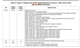
[6.188897]***   TLV 编解码器主 模式*******
[6.188900]***   TLV 编解码器右 J*******
[6.198037]****   I2S-C 从属设备***** CDNS_I2S_SET_fmt 409 sound/soc/cadence/cadence-I2S.c
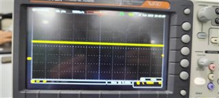
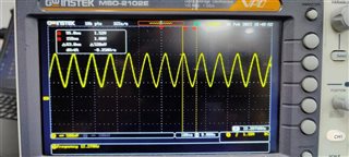
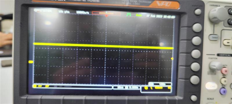
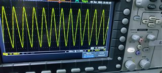
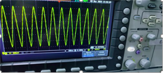
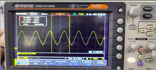
[6.211552]****   I2S-C I2S 正常***** CDNS_I2S_SET_fmt 458 sound/soc/cadence/cadence-I2S.c
这样做后,我们无法捕获或播放任何 wav 文件,我们怀疑主机无法生成时钟。
我已经为所有编解码器寄存器设置附加了 shell 脚本。
#########################################
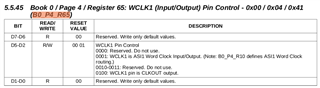
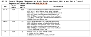
#codec-18.sh 
#########################################
#Software reset
i2cset -f -y 2 0x19 0x0 0x0
i2cset -f -y 2 0x19 0x7f 0x0
i2cset -f -y 2 0x19 0x1 0x1

#clock configuration(same for asi1 & as2)
i2cset -f -y 2 0x19 0x0 0x0
i2cset -f -y 2 0x19 0x4 0x0
i2cset -f -y 2 0x19 0xb 0x81
i2cset -f -y 2 0x19 0xc 0x82
i2cset -f -y 2 0x19 0xd 0x00
i2cset -f -y 2 0x19 0xe 0x80

i2cset -f -y 2 0x19 0x12 0x81
i2cset -f -y 2 0x19 0x13 0x82
i2cset -f -y 2 0x19 0x14 0x80

#power & analog configuration
i2cset -f -y 2 0x19 0x0 0x1
i2cset -f -y 2 0x19 0x1 0x0
i2cset -f -y 2 0x19 0x7a 0x1
i2cset -f -y 2 0x19 0x79 0x33 # ref charging time 

#audio serial interface routing configuration for ASI1
i2cset -f -y 2 0x19 0x0 0x4
i2cset -f -y 2 0x19 0x1 0x00
i2cset -f -y 2 0x19 0x8 0xf0
i2cset -f -y 2 0x19 0xa 0x24 # Master mode set for B0_P4_R10

#signal processing setting
i2cset -f -y 2 0x19 0x0 0x0
i2cset -f -y 2 0x19 0x3c 0x1
i2cset -f -y 2 0x19 0x3d 0x1 


#output channel configuration
i2cset -f -y 2 0x19 0x0 0x1
i2cset -f -y 2 0x19 0x3 0x0
i2cset -f -y 2 0x19 0x4 0x0
i2cset -f -y 2 0x19 0x1b 0x30 

i2cset -f -y 2 0x19 0x0 0x0
i2cset -f -y 2 0x19 0x3f 0xc0

i2cset -f -y 2 0x19 0x0 0x1
i2cset -f -y 2 0x19 0x1f 0xb9
i2cset -f -y 2 0x19 0x20 0xb9

i2cset -f -y 2 0x19 0x21 0x28 
i2cset -f -y 2 0x19 0x22 0x3e
i2cset -f -y 2 0x19 0x23 0x30
i2cset -f -y 2 0x19 0x1f 0x80 # 
i2cset -f -y 2 0x19 0x20 0x80

i2cset -f -y 2 0x19 0x0 0x0
i2cset -f -y 2 0x19 0x40 0x40

i2cset -f -y 2 0x19 0x0 0x1
i2cset -f -y 2 0x19 0x09 0x70
i2cset -f -y 2 0x19 0x1b 0x33

i2cset -f -y 2 0x19 0x0 0x1
i2cset -f -y 2 0x19 0x09 0x10

#adc config
i2cset -f -y 2 0x19 0x0 0x1
i2cset -f -y 2 0x19 0x8 0x0
i2cset -f -y 2 0x19 0x34 0x20 #diff
i2cset -f -y 2 0x19 0x36 0x80
i2cset -f -y 2 0x19 0x37 0x20 #diff
i2cset -f -y 2 0x19 0x39 0x80
i2cset -f -y 2 0x19 0x3b 0x0c #diff
i2cset -f -y 2 0x19 0x3c 0x0c #diff
i2cset -f -y 2 0x19 0x3d 0x0

i2cset -f -y 2 0x19 0x0 0x0
i2cset -f -y 2 0x19 0x51 0xc0
i2cset -f -y 2 0x19 0x52 0x0
谢谢和 BR
Rizwan Chikodi.
  • 请注意,本文内容源自机器翻译,可能存在语法或其它翻译错误,仅供参考。如需获取准确内容,请参阅链接中的英语原文或自行翻译。

    您好!

    从 MCLK1=12.288MHz 的寄存器设置中、您应该会看到48kHz 的 WCLK1和3.072MHz 的 BCLK1、您是否在示波器上看到该结果?

    您的设置与本参考指南4.1.1部分中的示例类似、除了该模块处于从模式、所以该模块可以工作。

    https://www.ti.com/lit/ug/slau309/slau309.pdf?ts=1676585354030&ref_url=https%253A%252F%252Fwww.ti.com%252Fproduct%252FTLV320AIC3262

    e2e.ti.com/.../settings.txt

    因此、先检查设置中的时钟。

    此致。

  • 请注意,本文内容源自机器翻译,可能存在语法或其它翻译错误,仅供参考。如需获取准确内容,请参阅链接中的英语原文或自行翻译。

    您好!

    我曾尝试探测 WCLK 和 BCLK、但在示波器上看不到任何时钟生成。

    我已经连接了波形的快照


    谢谢和 BR

  • 请注意,本文内容源自机器翻译,可能存在语法或其它翻译错误,仅供参考。如需获取准确内容,请参阅链接中的英语原文或自行翻译。

    您好!  

    您是否已检查"MCLK is present in the scope and codec is found as the sound card?

    盛浩

    您能帮助 Linux 方面吗? 配置正确、但没有来自编解码器的时钟。  

    此致。

  • 请注意,本文内容源自机器翻译,可能存在语法或其它翻译错误,仅供参考。如需获取准确内容,请参阅链接中的英语原文或自行翻译。

    你好、pdjuandi  

    我们之前已经验证过 I2S 控制器作为主器件、TLV320作为从器件、其工作正常。 这意味着编解码器正在获得 MCLK。

    但是、当将 TLV320编解码器配置为主器件时、I2S 控制器作为从器件时、我们成功找到了声卡寄存器、但无法看到 BCLK 和 WCLK 时钟。

    此外、我们会在录制和播放期间遇到输入/输出错误、如下所述

    ARecord -DHW:0、0 -f S16_LE -r 44100 -c 2 Codec-master.wav

    aplay -DHW:0、0 -f S16_LE -r 44100 -c 2 Codec-master.wav

    声卡检测:

    [6.760529] ALSA 设备列表:
    [6.763527]#0: tlv320aic3262-hif
    [6.767123]#1:NB2、PDM-MIC1.
    [6.770184]#2: nb2, sdac-播放

    谢谢 BR

  • 请注意,本文内容源自机器翻译,可能存在语法或其它翻译错误,仅供参考。如需获取准确内容,请参阅链接中的英语原文或自行翻译。

    您好!

    对于主模式、我们需要确保 MCLK 是正确的。 您能否使用示波器捕获 MCLK?

    请提供 Linux 错误、以便我们的固件团队帮助分析该错误。

    此致。

  • 请注意,本文内容源自机器翻译,可能存在语法或其它翻译错误,仅供参考。如需获取准确内容,请参阅链接中的英语原文或自行翻译。

    Sure 将提供有关这方面的更多信息。

  • 请注意,本文内容源自机器翻译,可能存在语法或其它翻译错误,仅供参考。如需获取准确内容,请参阅链接中的英语原文或自行翻译。

    您好...

    我在下面提到了输入输出误差

    root@:~# aplay -DHW:0,0/usr/share/sounds/alsa /*
    Playing wave '/usr/share/sounds/alsa/Front_Center.wav : Signed 16 bit Little Endian, RATE 48000Hz, Mono.
    播放:PCM_WRITE:2059:写入错误:输入/输出错误
    root@:~#

    为了测量音频 MCLK 时钟、我们需要在完成后做一些硬件修改、这样我们将捕获波形并向您发送 asap。

    非常感谢

  • 请注意,本文内容源自机器翻译,可能存在语法或其它翻译错误,仅供参考。如需获取准确内容,请参阅链接中的英语原文或自行翻译。

    好的、我已请我们的 Linux 专家对该错误作出评论。

  • 请注意,本文内容源自机器翻译,可能存在语法或其它翻译错误,仅供参考。如需获取准确内容,请参阅链接中的英语原文或自行翻译。

    您好、Rizwan

    Peter 为代码提供了配置主模式的 I2C 脚本、您能否在使用示波器的同一图中提供 MCLK、WS clk 和 bit clk 吗?

    在我看来、如果 mlck 对 i2c 脚本启用、编解码器应该工作正常。 如果这很有效、我们可以检查代码。

    Br

    丁圣浩

  • 请注意,本文内容源自机器翻译,可能存在语法或其它翻译错误,仅供参考。如需获取准确内容,请参阅链接中的英语原文或自行翻译。

    您好、Shenghao

    我使用音频 MCLK、BCLK 和 WCLK 进行了检查。

    我能够在示波器上看到音频 MCLK 时钟波形、如下所述

    并且无法在示波器上看到 BCLK 和 WCLK 时钟

    非常感谢

    Rizwan Chikodi.

  • 请注意,本文内容源自机器翻译,可能存在语法或其它翻译错误,仅供参考。如需获取准确内容,请参阅链接中的英语原文或自行翻译。

    只需确认运行 i2c 脚本而不是代码后是否捕获了所有图表、对吧?  

  • 请注意,本文内容源自机器翻译,可能存在语法或其它翻译错误,仅供参考。如需获取准确内容,请参阅链接中的英语原文或自行翻译。

    可以。

  • 请注意,本文内容源自机器翻译,可能存在语法或其它翻译错误,仅供参考。如需获取准确内容,请参阅链接中的英语原文或自行翻译。

    请在运行该 i2c 脚本期间转储寄存器。

    另外、有三个 MCLK 引脚、它们是 mclk1/mclk2/mclk3、您测量的是哪一个?

    至于 bck 和 wclk 引脚、仍然有三组。 您衡量的是哪个组?

  • 请注意,本文内容源自机器翻译,可能存在语法或其它翻译错误,仅供参考。如需获取准确内容,请参阅链接中的英语原文或自行翻译。

    I2C 转储寄存器详细信息:

    运行 i2c 脚本后测试

    root@codec18-configs\i2cdump -f -y 2 0x18.
    未指定大小(使用字节数据访问)
    0 1 2 3 4 5 6 7 8 9 a b c d e f 0123456789abcdef
    00:00 00 00 b0 00 00 00 11 04 00 01 81 82 00 80 00 ...?????????
    10:00 00 81 82 80 00 01 0f 80 00 18 6a 20 00 06。
    20:1A 00 00 cc 88 ee 00 00 00 00 00 00 00 00 00????........
    30:00 00 00 00 00 00 00 00 00 00 00 00 00 01 01 00 c0 .......... ????
    40:40 00 00 00 6F 00 00 00 00 00 00 ee 10 D8 7e E3 @…… ???~?
    50:00 c0 00 00 00 00 00 00 7f 00 00 00 00 00 00 00…… ?……
    60:7F 00 00 00 00 00 00 00 00 00 00 00 00 00 00 00 00 00?..........
    70:00 00 00 00 00 00 00 00 00 00 00 00 00 00 03 01 00 .......... ???
    80:00 00 00 00 00 00 00 00 00 00 00 00 00 00 00 00 00 00
    90:00 00 00 00 00 00 00 00 00 00 00 00 00 00 00 00 00 00
    A0:00 00 00 00 00 00 00 00 00 00 00 00 00 00 00 00 00 00
    B0:00 00 00 00 00 00 00 00 00 00 00 00 00 00 00 00 00 00
    C0:00 00 00 00 00 00 00 00 00 00 00 00 00 00 00 00 00 00
    D0:00 00 00 00 00 00 00 00 00 00 00 00 00 00 00 00 00 00
    E0:00 00 00 00 00 00 00 00 00 00 00 00 00 00 00 00 00 00
    F0:00 00 00 00 00 00 00 00 00 00 00 00 00 00 00 00 00 00
    (反向`搜索失败)"播放":CD ^Cdio/
    root@codec18-configs# aplay -DHW:0、0 /usr/share/sounds/alsa *和
    [1 ] 552.
    Playing wave '/usr/share/sounds/alsa/Front_Center.wav : Signed 16 bit Little Endian, RATE 48000Hz, Mono.
    root@codec18-configs#
    root@codec18-configs\i2cdump -f -y 2 0x18.
    未指定大小(使用字节数据访问)
    0 1 2 3 4 5 6 7 8 9 a b c d e f 0123456789abcdef
    00:00 00 00 b0 00 00 00 11 04 00 01 81 82 00 80 00 ...?????????
    10:00 00 81 82 80 00 01 0f 80 00 18 6a 20 00 06。
    20:1A 00 00 cc 88 ee 00 00 00 00 00 00 00 00 00????........
    30:00 00 00 00 00 00 00 00 00 00 00 00 00 01 01 00 c0 .......... ????
    40:40 00 00 00 6F 00 00 00 00 00 00 ee 10 D8 7e E3 @…… ???~?
    50:00 c0 00 00 00 00 00 00 7f 00 00 00 00 00 00 00…… ?……
    60:7F 00 00 00 00 00 00 00 00 00 00 00 00 00 00 00 00 00?..........
    70:00 00 00 00 00 00 00 00 00 00 00 00 00 00 03 01 00 .......... ???
    80:00 00 00 00 00 00 00 00 00 00 00 00 00 00 00 00 00 00
    90:00 00 00 00 00 00 00 00 00 00 00 00 00 00 00 00 00 00
    A0:00 00 00 00 00 00 00 00 00 00 00 00 00 00 00 00 00 00
    B0:00 00 00 00 00 00 00 00 00 00 00 00 00 00 00 00 00 00
    C0:00 00 00 00 00 00 00 00 00 00 00 00 00 00 00 00 00 00
    D0:00 00 00 00 00 00 00 00 00 00 00 00 00 00 00 00 00 00
    E0:00 00 00 00 00 00 00 00 00 00 00 00 00 00 00 00 00 00
    F0:00 00 00 00 00 00 00 00 00 00 00 00 00 00 00 00 00 00
    root@codec18-configs# a 播放:PCM_WRITE:2059:写入错误:输入/输出错误

    [1]+ done(1) a play -DHW:0,0 /usr/share/sounds/alsa /*

    我们已经测量了 MCLK1 BCLK1和 WCLK1。

    对于 MCLK1、我们可以在示波器上看到时钟。 但是对于 BCLK1和 WCLK1、没有时钟信号。

    谢谢、此致

    Rizwan Chikodi.

  • 请注意,本文内容源自机器翻译,可能存在语法或其它翻译错误,仅供参考。如需获取准确内容,请参阅链接中的英语原文或自行翻译。

    请提供 book0 page4寄存器转储

  • 请注意,本文内容源自机器翻译,可能存在语法或其它翻译错误,仅供参考。如需获取准确内容,请参阅链接中的英语原文或自行翻译。

    您好、Shenghao:

    对于 Book0和 Page 4、我们仅在寄存器下方进行设置

    i2cset -f -y 2 0x18 0x0 0x4
    i2cset -f -y 2 0x18 0x1 0x00
    i2cset -f -y 2 0x18 0x8 0xf0
    i2cset -f -y 2 0x18 0xA 0x24

    您的意思是我们还需要设置 B0_P4_R86_D[6:2]寄存器吗?

    非常感谢

  • 请注意,本文内容源自机器翻译,可能存在语法或其它翻译错误,仅供参考。如需获取准确内容,请参阅链接中的英语原文或自行翻译。

    根据数据表、它会执行此操作。

  • 请注意,本文内容源自机器翻译,可能存在语法或其它翻译错误,仅供参考。如需获取准确内容,请参阅链接中的英语原文或自行翻译。

    我们只需要通过 i2cset 设置该 B0_P4_R86_D[6:2]寄存器?

    如果是,则值0x86为?

  • 请注意,本文内容源自机器翻译,可能存在语法或其它翻译错误,仅供参考。如需获取准确内容,请参阅链接中的英语原文或自行翻译。

    让我内部检查一下。

  • 请注意,本文内容源自机器翻译,可能存在语法或其它翻译错误,仅供参考。如需获取准确内容,请参阅链接中的英语原文或自行翻译。

    好的

  • 请注意,本文内容源自机器翻译,可能存在语法或其它翻译错误,仅供参考。如需获取准确内容,请参阅链接中的英语原文或自行翻译。

    您好,Rizwan:  

    似乎我们目前在软件/固件方面找不到问题。 我想检查一下我们是否发现硬件有问题。 对于每个时钟、您要测量哪些引脚? 能否分享原理图、应用图和/或测试设置?  

    如果可能、下一步是使用逻辑分析仪来查看在写入 I2C 命令时直接在每个引脚上测量时显示的数据。 如果有可能、请告诉我。

    此致!
    Andrew

  • 请注意,本文内容源自机器翻译,可能存在语法或其它翻译错误,仅供参考。如需获取准确内容,请参阅链接中的英语原文或自行翻译。

    您好、Andrew Jackiw

    我将与我们的内部团队讨论尽快与您联系。

    非常感谢

    Rizwan

  • 请注意,本文内容源自机器翻译,可能存在语法或其它翻译错误,仅供参考。如需获取准确内容,请参阅链接中的英语原文或自行翻译。

    Rizwan,

    感谢您耐心解决此问题。 我期待您的答复。

    -安德鲁

  • 请注意,本文内容源自机器翻译,可能存在语法或其它翻译错误,仅供参考。如需获取准确内容,请参阅链接中的英语原文或自行翻译。

    您好、Andrew Jackiw

    我当时正忙于使用耳机麦克风支持服务。

    我已经开始处理这个 TT、我将尽快与您分享原理图

    谢谢 BR

    Rizwan Chikodi.

  • 请注意,本文内容源自机器翻译,可能存在语法或其它翻译错误,仅供参考。如需获取准确内容,请参阅链接中的英语原文或自行翻译。

    您好、Andrew Jackiw

    我附上了音频子卡原理图 pdf。 请检查并告诉我还有什么需要。

    谢谢

    Rizwan

  • 请注意,本文内容源自机器翻译,可能存在语法或其它翻译错误,仅供参考。如需获取准确内容,请参阅链接中的英语原文或自行翻译。

    无法在此处附上原理图 pdf。

  • 请注意,本文内容源自机器翻译,可能存在语法或其它翻译错误,仅供参考。如需获取准确内容,请参阅链接中的英语原文或自行翻译。

    尊敬的 Rizwan:

    I2C 引脚是否已连接至上拉电阻器? 您是否可以遵循 Andrew 的建议并测量 I2C 事务? 具体来说、是写入和读取有效吗?

    谢谢!

    Jeff McPherson

  • 请注意,本文内容源自机器翻译,可能存在语法或其它翻译错误,仅供参考。如需获取准确内容,请参阅链接中的英语原文或自行翻译。

    尊敬的 Jeff McPherson:

     I2C 上拉电阻器为 DNP (未附带)。

    仍然需要在没有 i2c 上拉电阻器的情况下检查 i2c 事务以进行读取和写入?

    谢谢和 BR

    Rizwan

  • 请注意,本文内容源自机器翻译,可能存在语法或其它翻译错误,仅供参考。如需获取准确内容,请参阅链接中的英语原文或自行翻译。

    尊敬的 Rizwan:

    如果没有上拉电阻器、I2C 总线将无法正常工作。 这些元件需要组装在板上。

    此致、

    Jeff McPherson

  • 请注意,本文内容源自机器翻译,可能存在语法或其它翻译错误,仅供参考。如需获取准确内容,请参阅链接中的英语原文或自行翻译。

    您好、Jeff

    我已填充 i2c 连接、但仍然无法捕获或播放音频。

    观察结果:

    -----------------------------------------------------------------------------------------------------------
    [6.623768]*** TLV 编解码器主模式*******
    [6.623772]*** TLV 编解码器右 J*******
    [6.633084]**** I2S-C 从属设备***** CDNS_I2S_SET_fmt 409 sound/soc/cadence/cadence-I2S.c
    [6.646612]**** I2S-C I2S 正常***** CDNS_I2S_SET_fmt 458 sound/soc/cadence/cadence-I2S.c
    [6.738817] cfg80211:为监管数据库加载编译的 X.509证书
    [6.760459] cfg80211:已加载 X.509证书"forshee:00b28ddf47aef9cea7"
    [6.767259] ALSA 设备列表:
    [6.770240]#0: tlv320aic3262-hif
    [6.776919]#2:SDAC-播放

    -----------------------------------------------------------------------------------------------------------
    I2C 读取/写入操作
    -----------------------------------------------------------------------------------------------------------
    root 用户@:~# i2cset -f -y 2 0x18 0xA 0x24
    root 用户@:~# i2cget -f -y 2 0x18 0xA
    0x24
    root@:~#
    -----------------------------------------------------------------------------------------------------------

    root@:~# arecord -l
    ****捕获硬件设备列表****
    卡0:tlv320aic3262hi [tlv320aic3262-hif]、设备0:300080000.i2s0-aic326x-asi1 aic326x-asi1-0 [300080000.i2s0-aic326x-asi1 aic326x-asi1-0]
    子器件:1/1
    子设备#0:子设备#0
    -----------------------------------------------------------------------------------------------------------
    root@:~# aplay -DHW:0,0/usr/share/sounds/alsa /*
    Playing wave '/usr/share/sounds/alsa/Front_Center.wav : Signed 16 bit Little Endian, RATE 48000Hz, Mono.
    播放:PCM_WRITE:2059:写入错误:输入/输出错误
    -----------------------------------------------------------------------------------------------------------

    运行 shell 脚本转储后、请参见下面的寄存器详细信息
    -----------------------------------------------------------------------------------------------------------
    root@:~# i2cdump -f -y 2 0x18.
    未指定大小(使用字节数据访问)
    0 1 2 3 4 5 6 7 8 9 a b c d e f 0123456789abcdef
    00:00 00 00 b0 00 00 00 11 04 00 01 81 82 00 80 00 ...?????????
    10:00 00 81 82 80 00 01 0f 80 00 18 6a 20 00 06。
    20:1A 00 00 cc 88 ff 00 00 00 00 00 00 00 00 00 00?...??
    30:00 00 00 00 00 00 00 00 00 00 00 00 00 01 01 00 c0 .......... ????
    40:4C 00 00 00 6F 00 00 00 00 00 00 00 ee 10 D8 7e E3 L. ???~?
    50:00 c0 00 00 00 00 00 00 7f 00 00 00 00 00 00 00…… ?……
    60:7F 00 00 00 00 00 00 00 00 00 00 00 00 00 00 00 00 00?..........
    70:00 00 00 00 00 00 00 00 00 00 00 00 00 00 03 01 00 .......... ???
    80:00 00 00 00 00 00 00 00 00 00 00 00 00 00 00 00 00 00
    90:00 00 00 00 00 00 00 00 00 00 00 00 00 00 00 00 00 00
    A0:00 00 00 00 00 00 00 00 00 00 00 00 00 00 00 00 00 00
    B0:00 00 00 00 00 00 00 00 00 00 00 00 00 00 00 00 00 00
    C0:00 00 00 00 00 00 00 00 00 00 00 00 00 00 00 00 00 00
    D0:00 00 00 00 00 00 00 00 00 00 00 00 00 00 00 00 00 00
    E0:00 00 00 00 00 00 00 00 00 00 00 00 00 00 00 00 00 00
    F0:00 00 00 00 00 00 00 00 00 00 00 00 00 00 00 00 00 00

    -----------------------------------------------------------------------------------------------------------

    我怀疑该问题可能在寄存器设置中、请告诉我您的想法。

    我已经附加了 shell 脚本。

    #########################################
    #codec-18.sh 
    #########################################
    #Software reset
    i2cset -f -y 2 0x18 0x0 0x0
    i2cset -f -y 2 0x18 0x7f 0x0
    i2cset -f -y 2 0x18 0x1 0x1
    
    #clock configuration(same for asi1 & as2)
    i2cset -f -y 2 0x18 0x0 0x0
    i2cset -f -y 2 0x18 0x4 0x0 # DAC_CLKIN=ADC_CLKIN=MCLK1
    i2cset -f -y 2 0x18 0xb 0x81 # NDAC powered and NDAC=1
    i2cset -f -y 2 0x18 0xc 0x82 # MDAC powered and MDAC=2
    i2cset -f -y 2 0x18 0xd 0x00 # 
    i2cset -f -y 2 0x18 0xe 0x80 # DOSR=128
    
    i2cset -f -y 2 0x18 0x12 0x81 # NADC powered and NADC=1
    i2cset -f -y 2 0x18 0x13 0x82 # MADC powered and MADC=2
    i2cset -f -y 2 0x18 0x14 0x80 # AOSR=128
    
    #power & analog configuration
    i2cset -f -y 2 0x18 0x0 0x1
    i2cset -f -y 2 0x18 0x1 0x0
    i2cset -f -y 2 0x18 0x7a 0x1 # Ref power up delay
    i2cset -f -y 2 0x18 0x79 0x33 # ref charging time 1.1ms
    
    #audio serial interface routing configuration for ASI1
    i2cset -f -y 2 0x18 0x0 0x4 
    i2cset -f -y 2 0x18 0x1 0x00 # ASI1=I2S, 16 bits
    i2cset -f -y 2 0x18 0x8 0xf0 # ASI1 Left and Right DAC mixed of Left and Right data
    i2cset -f -y 2 0x18 0xa 0x24 # Master mode 
    
    #signal processing setting
    i2cset -f -y 2 0x18 0x0 0x0
    i2cset -f -y 2 0x18 0x3c 0x1 # PRB_P1
    i2cset -f -y 2 0x18 0x3d 0x1 # PRB_R1
    
    
    #output channel configuration
    i2cset -f -y 2 0x18 0x0 0x1
    i2cset -f -y 2 0x18 0x3 0x0 # Left DAC in PTM_P3_P4
    i2cset -f -y 2 0x18 0x4 0x0 # Right DAC in PTM_P3_P4
    i2cset -f -y 2 0x18 0x1b 0x30 # Left DAC to HPL and Right DAC to HPR and powered down
    
    i2cset -f -y 2 0x18 0x0 0x0
    i2cset -f -y 2 0x18 0x3f 0xc0 # Left and Right DAC powered up
    
    i2cset -f -y 2 0x18 0x0 0x1
    i2cset -f -y 2 0x18 0x1f 0xb9 # HP Ground_Centered and HPL volume is muted
    i2cset -f -y 2 0x18 0x20 0xb9 # HPR=HPL and HPR volume is muted
    
    i2cset -f -y 2 0x18 0x21 0x28 # CP clock divide=4 default
    i2cset -f -y 2 0x18 0x22 0x3e # CP default
    i2cset -f -y 2 0x18 0x23 0x30 # CP auto power up
    i2cset -f -y 2 0x18 0x1f 0x80 # HP Ground_Centered and volume is 0dB
    i2cset -f -y 2 0x18 0x20 0x80 # HPR=HPL and HPR volume is 0dB
    
    i2cset -f -y 2 0x18 0x0 0x0
    i2cset -f -y 2 0x18 0x40 0x40 # Left and Right DAC not muted
    
    i2cset -f -y 2 0x18 0x0 0x1
    i2cset -f -y 2 0x18 0x09 0x70 # HP 25%
    i2cset -f -y 2 0x18 0x1b 0x33 # Left DAC to HPL and Right DAC to HPR and powered up
    
    i2cset -f -y 2 0x18 0x0 0x1
    i2cset -f -y 2 0x18 0x09 0x10 # HP 100%
    
    #adc config
    i2cset -f -y 2 0x18 0x0 0x1
    i2cset -f -y 2 0x18 0x8 0x0 # VOCM= Input CM
    i2cset -f -y 2 0x18 0x34 0x20 # IN2L P-Term 20K on Left_ADC
    i2cset -f -y 2 0x18 0x36 0x80 # CM 20K on M-Term on Left_ADC
    i2cset -f -y 2 0x18 0x37 0x20 # IN2R P-Term 20K on Right_ADC
    i2cset -f -y 2 0x18 0x39 0x80 # CM 20K on M-Term on Right_ADC
    i2cset -f -y 2 0x18 0x3b 0x0c # Left_ADC enabled with 6dB
    i2cset -f -y 2 0x18 0x3c 0x0c # Right_ADC enabled with 6dB
    i2cset -f -y 2 0x18 0x3d 0x0 # Default ADC PowerTune
    
    i2cset -f -y 2 0x18 0x0 0x0
    i2cset -f -y 2 0x18 0x51 0xc0 # Left and Right ADC powered up
    i2cset -f -y 2 0x18 0x52 0x0 # Left and Right ADC not muted

    谢谢。此致

    Rizwan Chikodi.

  • 请注意,本文内容源自机器翻译,可能存在语法或其它翻译错误,仅供参考。如需获取准确内容,请参阅链接中的英语原文或自行翻译。

    您好,Rizwan:

    很抱歉耽误你的时间。 寄存器设置时看到的波形。 请参阅以下建议/问题。

    • 请检查原理图中的连接。 根据使用的软件、它们将被视为未连接。 尽管不太可能、但请确认每个颜色连接都连接在布局/PCB 中。

    • 请执行单个 I2C 写入、然后读取寄存器以确认 I2C 总线正常工作。 终端显示一行,显示" 写入错误 " [报价 userid="553017" url="~/support/audio-group/audio/f/audio-forum/1197090/tlv320aic3262-configuration-of-tlv320aic3262-as-master-mode/4570750 #4570750"]root@:~# aplay -DHW:0、0 /usr/share/sounds/alsa /*
      Playing wave '/usr/share/sounds/alsa/Front_Center.wav : Signed 16 bit Little Endian, RATE 48000Hz, Mono.
      Aplay:PCM_WRITE:2059:写入错误:输入/输出错误
    • 请根据之前的要求提供 MCLK 的示波器捕获。
    • 请在"#output channel configuration"之前移动脚本的"#adc config"块
    • 这些测试脚本具有适用于时钟分频器的正确电源时序。
      • 分频器应按如下方式上电:'PLL'>'NDAC / NADC'>'MDAC / mAdc'。  
      • 您的脚本当前不遵循此顺序。

    此致!
    Andrew

  • 请注意,本文内容源自机器翻译,可能存在语法或其它翻译错误,仅供参考。如需获取准确内容,请参阅链接中的英语原文或自行翻译。

    您好、Andrew Jackiw

    • 在 PCB 中、上述所有连接均已连接并经过验证。
    • 如前面所述、I2C 读取/写入操作正常工作。
      • root 用户@:~# i2cset -f -y 2 0x18 0xA 0x24
        root 用户@:~# i2cget -f -y 2 0x18 0xA
        0x24
    • 我们可以看到上面提到的 MCLK1时钟
      •   
      • 但无法看到针对 BCLK 和 WCLK 线路的时钟信号。
    • 我已根据您的建议进行了检查、即在输出通道配置之前添加 ADC 配置块
      • #########################################
        #codec-18.sh 
        #########################################
        #Software reset
        i2cset -f -y 2 0x18 0x0 0x0
        i2cset -f -y 2 0x18 0x7f 0x0
        i2cset -f -y 2 0x18 0x1 0x1
        
        #clock configuration(same for asi1 & as2)
        i2cset -f -y 2 0x18 0x0 0x0
        i2cset -f -y 2 0x18 0x4 0x0 # DAC_CLKIN=ADC_CLKIN=MCLK1
        i2cset -f -y 2 0x18 0xb 0x81 # NDAC powered and NDAC=1
        i2cset -f -y 2 0x18 0xc 0x82 # MDAC powered and MDAC=2
        i2cset -f -y 2 0x18 0xd 0x00 # 
        i2cset -f -y 2 0x18 0xe 0x80 # DOSR=128
        
        i2cset -f -y 2 0x18 0x12 0x81 # NADC powered and NADC=1
        i2cset -f -y 2 0x18 0x13 0x82 # MADC powered and MADC=2
        i2cset -f -y 2 0x18 0x14 0x80 # AOSR=128
        
        #power & analog configuration
        i2cset -f -y 2 0x18 0x0 0x1
        i2cset -f -y 2 0x18 0x1 0x0
        i2cset -f -y 2 0x18 0x7a 0x1 # Ref power up delay
        i2cset -f -y 2 0x18 0x79 0x33 # ref charging time 1.1ms
        
        #audio serial interface routing configuration for ASI1
        i2cset -f -y 2 0x18 0x0 0x4 
        i2cset -f -y 2 0x18 0x1 0x00 # ASI1=I2S, 16 bits
        i2cset -f -y 2 0x18 0x8 0xf0 # ASI1 Left and Right DAC mixed of Left and Right data
        i2cset -f -y 2 0x18 0xa 0x24 # Master mode 
        
        #signal processing setting
        i2cset -f -y 2 0x18 0x0 0x0
        i2cset -f -y 2 0x18 0x3c 0x1 # PRB_P1
        i2cset -f -y 2 0x18 0x3d 0x1 # PRB_R1
        
        #adc config
        i2cset -f -y 2 0x18 0x0 0x1
        i2cset -f -y 2 0x18 0x8 0x0 # VOCM= Input CM
        i2cset -f -y 2 0x18 0x34 0x20 # IN2L P-Term 20K on Left_ADC
        i2cset -f -y 2 0x18 0x36 0x80 # CM 20K on M-Term on Left_ADC
        i2cset -f -y 2 0x18 0x37 0x20 # IN2R P-Term 20K on Right_ADC
        i2cset -f -y 2 0x18 0x39 0x80 # CM 20K on M-Term on Right_ADC
        i2cset -f -y 2 0x18 0x3b 0x0c # Left_ADC enabled with 6dB
        i2cset -f -y 2 0x18 0x3c 0x0c # Right_ADC enabled with 6dB
        i2cset -f -y 2 0x18 0x3d 0x0 # Default ADC PowerTune
        
        i2cset -f -y 2 0x18 0x0 0x0
        i2cset -f -y 2 0x18 0x51 0xc0 # Left and Right ADC powered up
        i2cset -f -y 2 0x18 0x52 0x0 # Left and Right ADC not muted
        
        #output channel configuration
        i2cset -f -y 2 0x18 0x0 0x1
        i2cset -f -y 2 0x18 0x3 0x0 # Left DAC in PTM_P3_P4
        i2cset -f -y 2 0x18 0x4 0x0 # Right DAC in PTM_P3_P4
        i2cset -f -y 2 0x18 0x1b 0x30 # Left DAC to HPL and Right DAC to HPR and powered down
        
        i2cset -f -y 2 0x18 0x0 0x0
        i2cset -f -y 2 0x18 0x3f 0xc0 # Left and Right DAC powered up
        
        i2cset -f -y 2 0x18 0x0 0x1
        i2cset -f -y 2 0x18 0x1f 0xb9 # HP Ground_Centered and HPL volume is muted
        i2cset -f -y 2 0x18 0x20 0xb9 # HPR=HPL and HPR volume is muted
        
        i2cset -f -y 2 0x18 0x21 0x28 # CP clock divide=4 default
        i2cset -f -y 2 0x18 0x22 0x3e # CP default
        i2cset -f -y 2 0x18 0x23 0x30 # CP auto power up
        i2cset -f -y 2 0x18 0x1f 0x80 # HP Ground_Centered and volume is 0dB
        i2cset -f -y 2 0x18 0x20 0x80 # HPR=HPL and HPR volume is 0dB
        
        i2cset -f -y 2 0x18 0x0 0x0
        i2cset -f -y 2 0x18 0x40 0x40 # Left and Right DAC not muted
        
        i2cset -f -y 2 0x18 0x0 0x1
        i2cset -f -y 2 0x18 0x09 0x70 # HP 25%
        i2cset -f -y 2 0x18 0x1b 0x33 # Left DAC to HPL and Right DAC to HPR and powered up
        
        i2cset -f -y 2 0x18 0x0 0x1
        i2cset -f -y 2 0x18 0x09 0x10 # HP 100%
        
    • 如果我们遗漏了需要传递的任何信息、请告知我们。
    • 在运行 aplay 命令时仍然会收到输入输出错误。

    谢谢 BR

    Rizwan Chikodi.

  • 请注意,本文内容源自机器翻译,可能存在语法或其它翻译错误,仅供参考。如需获取准确内容,请参阅链接中的英语原文或自行翻译。

    Rizwan,

    对于 Fs = 48kHz Fs 的主器件 I2S、您的配置看起来是正确的。 您能否确认 MCLK 频率和形状? MCLK 看起来像一个三角波形、通常建议 MCLK 具有~50%的占空比。 这是由示波器 BW 造成的吗? 您能否确保它是50%直流12.2876MHz 方波?

    此外、请检查电源。 所有电源、如 DVDD、IOVDD、是否均已启动且稳定?

    还请 读回寄存器 B0_P4_R65和 B0_P4_R10?

    此致!
    Andrew

  • 请注意,本文内容源自机器翻译,可能存在语法或其它翻译错误,仅供参考。如需获取准确内容,请参阅链接中的英语原文或自行翻译。

    您好、Andrew

    • 我不确定如何检查 MCLK1时钟的方波形  

          我们在使用 dwinstek 示波器。

    • 我测量了 DVDD 和 IOVDD 提供1.8伏。

    ---------------- B0_P4_R65 -------------------------------------------------------
    root 用户@:~# i2cset -f -y 2 0x18 0x0 0x4.
    root 用户@:~# i2cget -f -y 2 0x18 0x41
    0x04
    root@:~#

    ---------------- B0_P4_R10----------------
    root 用户@:~# i2cset -f -y 2 0x18 0x0 0x4.
    root 用户@:~# i2cget -f -y 2 0x18 0x0A
    0x24
    root@:~#

    非常感谢

    Rizwan Chikodi.

  • 请注意,本文内容源自机器翻译,可能存在语法或其它翻译错误,仅供参考。如需获取准确内容,请参阅链接中的英语原文或自行翻译。

    您好,Rizwan:

    感谢您  迄今提供的宝贵意见。 根据您的寄存器配置、我们期望 WCLK 和 BCLK 作为器件的输出。 从示波器的设置和功能来看、波形可以正确地表示为三角波形。 目前、我们有两个建议/建议。

    1. 当 I2C 写入正在配置器件时、可能需要禁用 MCLK。 请在器件完全配置后启用 MCLK、并再次探测 WCLK 和 BCLK。
    2. MCLK 无效、器件需要更方形的波形才能正常运行。 请为器件提供一个占空比为50%的方波 MCLK。  

    首先尝试单独实施第1项、然后同时实施第1项和第2项。 这将有助于确定 MCLK 是否是问题所在。  

    此致!
    Andrew