

Other Parts Discussed in Thread: ADS1219
请注意,本文内容源自机器翻译,可能存在语法或其它翻译错误,仅供参考。如需获取准确内容,请参阅链接中的英语原文或自行翻译。
器件型号:ADS1219您好 TI、
我的 ADS1219IRTER 似乎无法正常工作。 我将 ADC 连接到 STM32F446RE、并尝试读取 AIN0 和 AIN1 之间的电压。 发送 ADC 开始同步命令 (0x80) 后、我始终得到一个 ADC 值不正确、即使输入 (AIN0 - AIN1) 发生变化也不会改变。 ADC 输入连接到一个简单的分压器、该分压器可衰减定制推挽式转换器的输出电压。 此推挽式转换器的输出电压会有所不同、但可以设置为 0.6V 至 1kV 之间的任何值、具体取决于 STM32 的占空比。 此设置的原理图如下所示 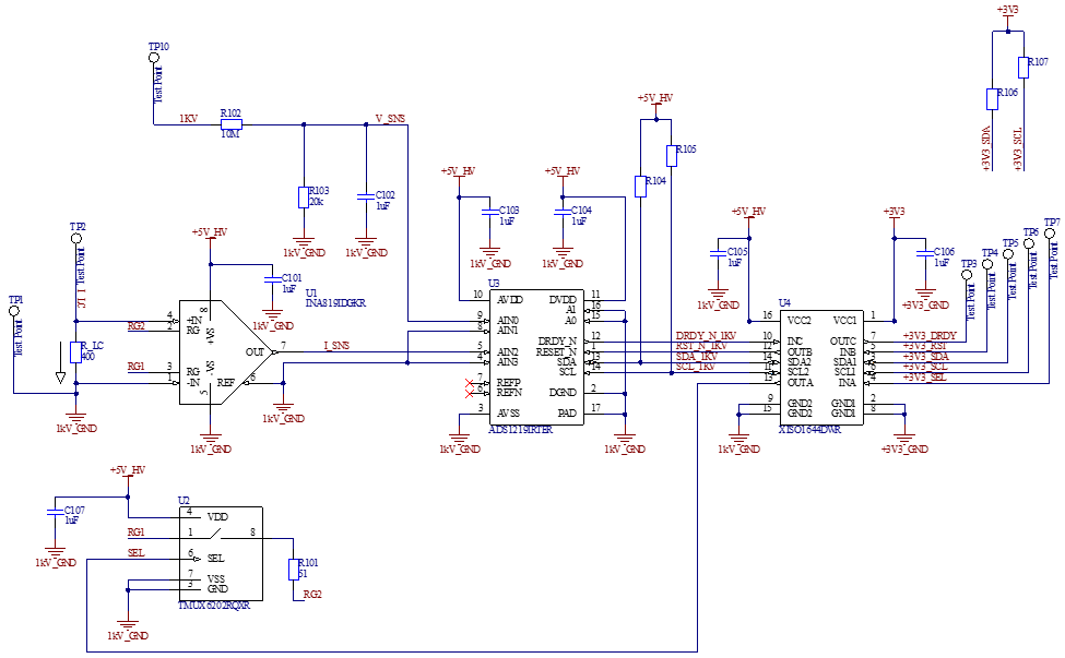
C201 由 5V 实验室电源供电。
TP3 -> PB5(GPIO 引脚)。
TP6 -> PB8 (I2C1 SCL)
TP4 -> PB6(持续设置为高电平)
TP7 -> PB7(持续低电平)
TP5 -> PB9 (I2C1 SDA)
C106 从 STM32 开发板获得电力。
主函数是 STM32 很简单。
- 配置 HAL
- 配置 UART (MODBUS)
- 通过两个计时器配置 PWM
- 为 ADC 配置 I2C。
int main(void)
{
	//Vars
	eMBErrorCode eStatus;

	//0. Initialize HAL
	HAL_Init();
	//1. System Clock Config
	SystemClock_Config();

	//2. GPIO Config
	//a. UART
	MX_GPIO_Init();
	HAL_Delay(10);
	//b. PWM
	MX_PWM_GPIO_Init();
	HAL_Delay(10);
	MX_TIM5_Master_Init();
	MX_TIM2_Slave_Init(420);
	//c. I2C for ADC
	MX_I2C_GPIO_Init();
	MX_I2C1_Init();
	ADC_RST_HIGH();

	//d. Configure ADC
	//set_adc_gain(1);
	//set_adc_mux(3);
	//set_adc_sps(20);
	//set_adc_cm(true);
	//set_adc_vref(false);
	//tx_adc_wreg();
	tx_adc_start_sync();

	//uint8_t config = rx_adc_rreg(0x0);

	//3. PWM Timer Init
	pwm_start();
	HAL_Delay(100);

	//4. I2C Test
	//rx_adc_count();

	//5. MODBUS
	//a. Initialize
	eStatus = eMBInit(MB_RTU, 0x0A, 0, 38400, MB_PAR_NONE, 1);
	usRegInputBuf[0] = 1;  /* Initialize counter */
	usRegInputBuf[1] = 0;
	usRegInputBuf[2] = 0;
	usRegInputBuf[3] = 0;

	//b. Enable the protocol stack.
	eStatus = eMBEnable();

	//c. Handle Errors
	if( eStatus != MB_ENOERR )
	  {
		  Error_Handler();
	  }

    /* Loop forever */
	for(;;)
	{
		(void)eMBPoll();
	}
}
我触发 STM32 在 MODBUS 回调函数中读取 ADC 值、
eMBErrorCode
eMBRegInputCB( UCHAR * pucRegBuffer, USHORT usAddress, USHORT usNRegs )
{
    eMBErrorCode    eStatus = MB_ENOERR;
    int             iRegIndex;

    //0. Sensor Type -> (0x01)
    //a. Check the register limits.
    if( ( usAddress == 0x01 ) && (usNRegs == 0x02 ) )
    {
        //ModBus Standard Packet Size is Two Bytes or a Unsigned Short
        //Smallest packet sends two bytes.
        //i. Move to the next packet frame. -> Assign 0x00;
        *pucRegBuffer++ = (UCHAR)(0x00);
        //ii. Move to the next packet frame. -> Assign 0x49 or "I".
        *pucRegBuffer++ = (UCHAR)(0x49);
    }
    //1. Current Input Register -> (0x02 to 0x04)
    //a. Check the register limits.
    else if( ( usAddress >= 0x02 ) && ( usNRegs == 0x02 ) )
    {
        //b. Get the current.
        g_f_current = get_voltage();
        //c. Convert float to ushort.
        modbus_set_float_us(g_f_current, &test_float_us);
        //iRegIndex = ( int )( usAddress - usRegInputStart );
        iRegIndex = usNRegs-1;
        //d. Copy current to ModBus Input Regs.
        while( usNRegs > 0)
        {
            *pucRegBuffer++ = (UCHAR)(test_float_us[iRegIndex] >> 8);
            *pucRegBuffer++ = (UCHAR)(test_float_us[iRegIndex] & 0xFF);
            iRegIndex--;
            usNRegs--;
        }
    }
    else
    {
        eStatus = MB_ENOREG;
    }
    return eStatus;
}
函数 get_voltage() 调用 rx_adc_count()、
float get_voltage()
{
    int32_t adc_count = rx_adc_count();
    float voltage = 0;
    if (g_enum_gain == one)
        voltage = (float)(adc_count*(2.0f*2.048f/1.0f)/16777216.0f);
    else
        voltage = (float)(adc_count*(2.0f*2.048f/4.0f)/16777216.0f);
    return voltage;
}
nt32_t rx_adc_count()
{
uint8_t adc_p[3];
uint8_t i2c_data = ADC_RDATA;
HAL_I2C_Master_Transmit(&hi2c1, SLAVE_ADDRESS, &i2c_data, 1, 10);
HAL_I2C_Master_Receive(&hi2c1, SLAVE_ADDRESS, &adc_p[0], 3, 10);
g_rx_adc_count = adc_p[0] << 16 | adc_p[1] << 8 | adc_p[2];
uint8_t pol_bit = g_rx_adc_count >> 23;
if (pol_bit == 0)
{
g_rx_adc_count_signed = g_rx_adc_count;
}
else
{
g_rx_adc_count_signed = g_rx_adc_count;
g_rx_adc_count_signed = g_rx_adc_count_signed - 16777216;
}
return g_rx_adc_count_signed;
}我已通过查看示波器上的 I2C 总线来验证 STM32 接收到的数据是否正确。

问题在于、当输入电压发生变化时、ADC 计数不会改变。
有人对我的行为有什么建议吗?
谢谢、
Allan
