This thread has been locked.

If you have a related question, please click the "Ask a related question" button in the top right corner. The newly created question will be automatically linked to this question.

[参考译文] PCF8574:数据表中的源电流图(图8、9和10)

Guru**** 2390735 points
Other Parts Discussed in Thread: PCF8574
请注意,本文内容源自机器翻译,可能存在语法或其它翻译错误,仅供参考。如需获取准确内容,请参阅链接中的英语原文或自行翻译。

https://e2e.ti.com/support/interface-group/interface/f/interface-forum/948794/pcf8574-source-current-graph-figure-8-9-and-10-in-the-datasheet

部件号:PCF8574

您好!

我对 PCF8574有疑问。

我对 PCF8574架构的理解是、其高输出意味着内部上拉电流为100uA、低输出意味着连接到 GND。
因此、由于内部电流源、我认为最大拉电流应小于100uA (最大300uA)。
但数据表中有图8、9和10、即 I/O 拉电流与输出高电压。
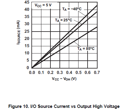


此图显示源电流为几个10mA。 我认为无法从该架构中获取 mA 阶电流。
图中的该拉电流是什么意思?

此致、
OBA

  • 请注意,本文内容源自机器翻译,可能存在语法或其它翻译错误,仅供参考。如需获取准确内容,请参阅链接中的英语原文或自行翻译。

    您好、Oba、

    我认为这可能是一个拼写错误、这些图上 y 轴的单位可能是 uA、而不是 mA。

    -Bobby