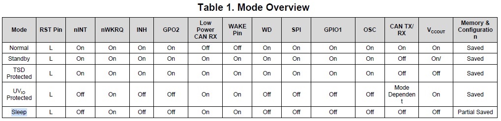
Other Parts Discussed in Thread: TCAN4550EVM, MSP430FR6989, TCAN4550
主题中讨论的其他器件: MSP430FR6989、 TCAN4550
您好!
我正在尝试 将 TCAN4550EVM 连接到我的 STM32F407VET6板、但我在第一步中遇到困难。 我甚至无法正确读取器件 ID。 我从地址'h000 &'h0004得到的是随机值。
我能够使用 USART 和 COM 功能 并 读取 MCU 板上闪存的器件 ID、因此 MCU 本身不会损坏。
我正在使用的编译器是 Keil V5 Lite。 网站上的代码示例似乎用于 其他编译器和 MCU、因此我无法直接使用。 我将代码简化为与 SPI 相关的代码、希望有人可以检查出任何问题。 我在 MCU 应用方面的经验非常有限。 可能是简单的错误。
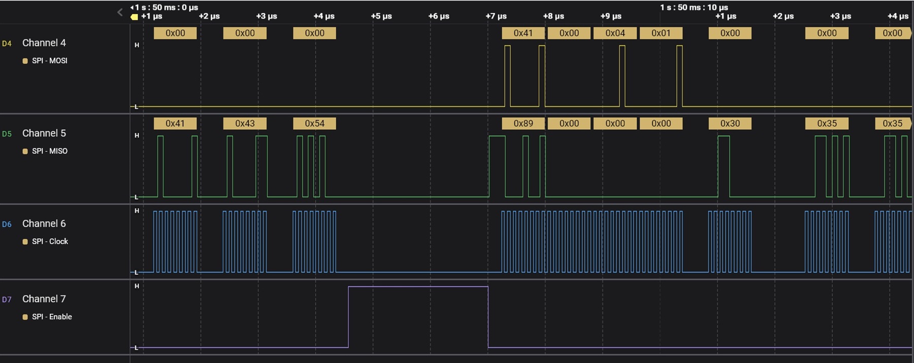
我将 SPI 频率设置为10MHz (APB 时钟为80MHz)、CPHA=0、CPOL=0。 仅连接6根导线:VBAT 和 GND 至12V 电源、SCLK 至 PA5、SDI 至 PA7、SDO 至 PA6、NCS 至 PA4。
void SPISendByte(unsigned char tmpData)
{
	while((SPI1->SR&2)==0);		//wait for TXE
	SPI1->DR = tmpData;
}
unsigned char SPIGetByte()
{
	while((SPI1->SR&2)==0);		//wait for TXE
	while(SPI1->SR&(1<<7));		//wait for !BSY
	SPI1->DR = 0;		//send dummy data
	while(!(SPI1->SR&1));		//wait for RXNE
	return SPI1->DR;
}

void TCANReadBytes(unsigned short address, unsigned char *tmpC, unsigned short len1)
{
	GPIOA->BSRRH |= GPIO_Pin_4;		//set to 0, enable
	SPISendByte(0x41);		//read
	SPISendByte(address>>8);		//MSB
	SPISendByte(address&0xFF);		//LSB
	SPISendByte(len1);		//len1*32bit
	while((SPI1->SR&2)==0);		//wait for TXE
	while(SPI1->SR&(1<<7));		//wait for !BSY
	SPI1->DR;		//read the last dummy byte
	for (unsigned short idx1=0; idx1<len1*4; ++idx1)
		tmpC[idx1] = SPIGetByte();
	GPIOA->BSRRL |= GPIO_Pin_4;		//set to 1, disable
}

int main(void)
{
	NVIC_PriorityGroupConfig(NVIC_PriorityGroup_2);
	USART1_Init(115200);

	//SPI settings
	RCC->AHB1ENR |= RCC_AHB1Periph_GPIOA;
	GPIO_InitTypeDef GPIO_InitStructure;

	GPIO_InitStructure.GPIO_Pin   = GPIO_Pin_4;		//nCS
	GPIO_InitStructure.GPIO_Speed = GPIO_Speed_50MHz;
	GPIO_InitStructure.GPIO_Mode  = GPIO_Mode_OUT;
	GPIO_InitStructure.GPIO_OType = GPIO_OType_PP;
	GPIO_InitStructure.GPIO_PuPd  = GPIO_PuPd_UP;
	GPIO_Init(GPIOA, &GPIO_InitStructure);

	GPIOA->BSRRL |= GPIO_Pin_4;		//set to 1, disable NCS

	GPIO_InitStructure.GPIO_Pin = GPIO_Pin_5 | GPIO_Pin_6 | GPIO_Pin_7;
	GPIO_InitStructure.GPIO_Mode = GPIO_Mode_AF;
	GPIO_InitStructure.GPIO_OType = GPIO_OType_PP;
	GPIO_InitStructure.GPIO_PuPd = GPIO_PuPd_NOPULL;
	GPIO_Init(GPIOA, &GPIO_InitStructure);

	GPIO_PinAFConfig(GPIOA, GPIO_PinSource5, GPIO_AF_SPI1);
	GPIO_PinAFConfig(GPIOA, GPIO_PinSource6, GPIO_AF_SPI1);
	GPIO_PinAFConfig(GPIOA, GPIO_PinSource7, GPIO_AF_SPI1);

	RCC->APB2ENR |= (1<<12);		//enable SPI1 clock
	SPI1->CR1 |= 0 << 0;		//CPHA = 0
	SPI1->CR1 |= 0 << 1;		//CPOL = 0
	SPI1->CR1 |= 1 << 2;		//master mode
	SPI1->CR1 |= 2 << 3;		//baudrate = fPCLK /8
	SPI1->CR1 |= 0 << 7;		//MSB first
	SPI1->CR1 |= 1 << 9;		//software slave management
	SPI1->CR1 |= 1 << 8;		//software slave internal
	SPI1->CR1 |= 0 << 10;		//RXonly =0, full-duplex
	SPI1->CR1 |= 0 << 11;		//frame format: 8 bit data
	SPI1->CR1 |= 1 << 6;		//enable external

	unsigned char tmpC[5];
	tmpC[4] = 10;
	for(int idx1=0;idx1<8;idx1=idx1+4)
	{
		tmpC[0] = 0;
		tmpC[1] = 0;
		tmpC[2] = 0;
		tmpC[3] = 0;
		TCANReadBytes(idx1, tmpC, 1);
		USART1SendChar((char*)tmpC, 5);		//send the response to PC via COM port
	}

	while (1)
	{
	}
}
响应将
[ 2023年07月20日10:43:10.502]#接收十六进制>
00 00 00 00 0A C0 7F F2 40 0A
[ 2023年07月20日10:43:12.824]#接收十六进制>
FF EA 00 0A 02 00 00 0A
[ 2023年07月20日10:43:15.247]#接收十六进制>
FF FF 92 00 0A 02 00 00 0A
[ 2023年07月20日10:43:17.708]#接收十六进制>
FF F5 40 0A 02 00 00 0A
[ 2023年07月20日10:43:20.001]#接收十六进制>
FF FF 92 00 0A 00 00 00 0A
[ 2023年07月20日10:43:23.255]#接收十六进制>
00 00 00 00 0A 00 00 52 0A
[ 2023年07月20日10:43:25.510]#接收十六进制>
FF FF 89 00 0A 00 01 39 05 0A
[ 2023年07月20日10:43:27.581]#接收十六进制>
00 00 00 00 0A 00 00 00 0A
[ 2023年07月20日10:43:29.656]#接收十六进制>
00 00 00 00 0A 00 00 00 0A
[ 2023年07月20日10:43:31.665]#接收十六进制>
00 00 00 00 0A 00 00 00 0A
[ 2023年07月20日10:43:33.786]#接收十六进制>
00 00 00 00 0A 00 00 00 0A
[ 2023年07月20日10:43:35.888]#接收十六进制>
00 00 00 00 0A 00 00 00 0A
[ 2023年07月20日10:43:38.188]#接收十六进制>
7F FF FF 0A C4 80 00 00 0A
[ 2023年07月20日10:43:40.176]# RECV HEXE>
FF FF 92 00 0A 00 01 39 05 0A
我尝试在 MCU 启动期间读取 TCAN ID、并使用 MCU 板的复位按钮对其进行了测试。