请注意,本文内容源自机器翻译,可能存在语法或其它翻译错误,仅供参考。如需获取准确内容,请参阅链接中的英语原文或自行翻译。
器件型号:TCAN4550 您好!
我正在尝试为我的微控制器设置 STM32修改其中包含的 TCAN4550演示代码。 为了测试实现情况、我尝试读取器件 ID 寄存器。 但是、每当我尝试读取时、我总是会得到值0 out。 我敢肯定这可能意味着我的 SPI 实施不正确、但我还想布置好一般设置、看看我是否漏掉了任何东西。 此外、为了便于参考、我使用 TCAN 升压模块并将其与 STM32 Nucleo 板连接。
SPI 参数(对于 MCU):
时钟频率:10.5MBit/s
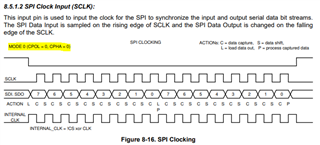
CPOL = 0、CPHA = 1边沿
帧格式:Motorola MSB 优先、数据大小:8位、 全双工主机
在我的代码中、首先要做的是对 TCAN 上的 RST 引脚施加脉冲之前将 NCS 引脚设置为高电平(我使用升压模块上的 GPIO_RST 引脚)。 对其进行脉冲之后、我发现升压模块上的 VCCOUT 和 nINT LED 处于活动状态。 我确定这意味着 TCAN 处于待机状态? 我不确定 nINT LED 为什么亮起、无论如何我都无法读取器件中断寄存器。 RST 脉冲后、我意外地尝试读取器件 ID 寄存器。
我通过直流桶形插孔使用12V 电压为升压模块供电。 我也只将 SPI 接口、GND 和 RST 引脚连接至 TCAN 板。 以下是我执行 SPI 功能的设置。
void SPI_WRITE_32(SPI_HandleTypeDef *hspi, uint16_t address, uint8_t num_words, uint32_t pData)
{
    SPI_WRITE_BURST_START(hspi, address, num_words, pData);
    SPI_WRITE_BURST_WRITE(hspi, address, num_words, pData);
    SPI_WRITE_BURST_END();
}

uint32_t
SPI_READ_32(SPI_HandleTypeDef *hspi, uint16_t address)
{
    uint32_t returnData;

    SPI_READ_BURST_START(hspi, address, 1);
    returnData = SPI_READ_BURST_READ(hspi, address);
    SPI_READ_BURST_END();

    return returnData;
}

/*
 * @brief Burst write start
 *
 * The SPI transaction contains 3 parts: the header (start), the payload, and the end of data (end)
 * This function is the start, where the register address and number of words are transmitted
 *
 * @param address A 16-bit address of the destination register
 * @param words The number of 4-byte words that will be transferred. 0 = 256 words
 */
void SPI_WRITE_BURST_START(SPI_HandleTypeDef *hspi, uint16_t address, uint8_t num_words, uint32_t pData)
{

    // Prepare the data for SPI transmission
	// Prepare the data for SPI transmission
	uint16_t opcodeAndHighAddress = (WRITE_OPCODE << 8) | ((address >> 8) & 0xFF);
	uint16_t lowAddressAndNumWords = ((address & 0xFF) << 8) | num_words;

	// Create a 32-bit value from the prepared data
	uint32_t combinedValue = ((uint32_t)opcodeAndHighAddress << 16) | lowAddressAndNumWords;

	// Extract individual 8-bit values
	uint8_t msb = (combinedValue >> 24) & 0xFF; // Most significant byte
	uint8_t byte2 = (combinedValue >> 16) & 0xFF;
	uint8_t byte1 = (combinedValue >> 8) & 0xFF;
	uint8_t lsb = combinedValue & 0xFF;         // Least significant byte

    // set CS gpio low
    HAL_GPIO_WritePin(GPIOC, nCS_Pin, GPIO_PIN_RESET);

    // Send the first 16-bit SPI packet (opcode and top 8 bits of address)
    HAL_StatusTypeDef status = HAL_SPI_Transmit(hspi, &msb, sizeof(byte3), HAL_MAX_DELAY);
    HAL_SPI_Transmit(hspi, &byte2, sizeof(byte2), HAL_MAX_DELAY);
    HAL_SPI_Transmit(hspi, &byte1, sizeof(byte1), HAL_MAX_DELAY);
    HAL_SPI_Transmit(hspi, &lsb, sizeof(byte0), HAL_MAX_DELAY);

}

/*
 * @brief Burst write
 *
 * The SPI transaction contains 3 parts: the header (start), the payload, and the end of data (end)
 * This function writes a single word at a time
 *
 * @param data A 32-bit word of data to write to the destination register
 */
void SPI_WRITE_BURST_WRITE(SPI_HandleTypeDef *hspi, uint8_t num_words, uint16_t address, uint32_t pData)
{
	uint8_t byte3 = (pData >> 24) & 0xFF; // Most significant byte
	uint8_t byte2 = (pData >> 16) & 0xFF;
	uint8_t byte1 = (pData >> 8) & 0xFF;
	uint8_t byte0 = pData & 0xFF;          // Least significant byte

	// Send the first 16-bit SPI packet (opcode and top 8 bits of address)
	HAL_StatusTypeDef status = HAL_SPI_Transmit(hspi, &byte3, sizeof(byte3), HAL_MAX_DELAY);
	HAL_SPI_Transmit(hspi, &byte2, sizeof(byte2), HAL_MAX_DELAY);
	HAL_SPI_Transmit(hspi, &byte1, sizeof(byte1), HAL_MAX_DELAY);
	HAL_SPI_Transmit(hspi, &byte0, sizeof(byte0), HAL_MAX_DELAY);

}

/*
 * @brief Burst write end
 *
 * The SPI transaction contains 3 parts: the header (start), the payload, and the end of data (end)
 * This function ends the burst transaction by pulling nCS high
 */
void SPI_WRITE_BURST_END(void)
{
// set CS gpio high again to indicate the end of the burst
    HAL_GPIO_WritePin(GPIOC, nCS_Pin, GPIO_PIN_SET);
}

/*
 * @brief Burst read start
 *
 * The SPI transaction contains 3 parts: the header (start), the payload, and the end of data (end)
 * This function is the start, where the register address and number of words are transmitted
 *
 * @param address A 16-bit start address to begin the burst read
 * @param words The number of 4-byte words that will be transferred. 0 = 256 words
 */
void SPI_READ_BURST_START(SPI_HandleTypeDef *hspi, uint16_t address, uint8_t words)
{

	// Prepare the data for SPI transmission
	uint16_t opcodeAndHighAddress = (WRITE_OPCODE << 8) | ((address >> 8) & 0xFF);
	uint16_t lowAddressAndNumWords = ((address & 0xFF) << 8) | num_words;

	// Create a 32-bit value from the prepared data
	uint32_t combinedValue = ((uint32_t)opcodeAndHighAddress << 16) | lowAddressAndNumWords;

	// Extract individual 8-bit values
	uint8_t msb = (combinedValue >> 24) & 0xFF; // Most significant byte
	uint8_t byte2 = (combinedValue >> 16) & 0xFF;
	uint8_t byte1 = (combinedValue >> 8) & 0xFF;
	uint8_t lsb = combinedValue & 0xFF;         // Least significant byte

    // Set the CS low to start the transaction
    HAL_GPIO_WritePin(GPIOC, nCS_Pin, GPIO_PIN_RESET);

           // Send the first 16-bit SPI packet (opcode and top 8 bits of address)
    HAL_StatusTypeDef status = HAL_SPI_Transmit(hspi, &msb, sizeof(byte3), HAL_MAX_DELAY);
    HAL_SPI_Transmit(hspi, &byte2, sizeof(byte2), HAL_MAX_DELAY);
    HAL_SPI_Transmit(hspi, &byte1, sizeof(byte1), HAL_MAX_DELAY);
    HAL_SPI_Transmit(hspi, &lsb, sizeof(byte0), HAL_MAX_DELAY);

    // Send the 16-bit address
    // Send the first 16-bit SPI packet (opcode and top 8 bits of address)
    // Handle an SPI transmit error by trying again
    if (status != HAL_OK)
    {
        SPI_READ_ERR_HANDLER(hspi, address);
    }
}

/*
 * @brief Burst read start
 *
 * The SPI transaction contains 3 parts: the header (start), the payload, and the end of data (end)
 * This function where each word of data is read from the TCAN4x5x
 *
 * @return A 32-bit single data word that is read at a time
 */
uint32_t
SPI_READ_BURST_READ(SPI_HandleTypeDef *hspi, uint16_t address)
{
	uint8_t readData0;
	uint8_t readData1;
	uint8_t readData2;
	uint8_t readData3;
	uint32_t returnData;

	HAL_SPI_Receive (hspi, &readData0, sizeof(readData0), HAL_MAX_DELAY);
	HAL_SPI_Receive (hspi, &readData1, sizeof(readData1), HAL_MAX_DELAY);
	HAL_SPI_Receive (hspi, &readData2, sizeof(readData2), HAL_MAX_DELAY);
	HAL_SPI_Receive (hspi, &readData3, sizeof(readData3), HAL_MAX_DELAY);

	returnData = (((uint32_t)readData0) << 24) | (((uint32_t)readData1 << 16)) | (((uint32_t)readData2) << 8) | readData3;

	return returnData;

}

/*
 * @brief Burst write end
 *
 * The SPI transaction contains 3 parts: the header (start), the payload, and the end of data (end)
 * This function ends the burst transaction by pulling nCS high
 */
void SPI_READ_BURST_END(void)
{
    // set CS gpio high
    HAL_GPIO_WritePin(GPIOC, nCS_Pin, GPIO_PIN_SET);
}
我因此调用 SPI_READ_32:
uint32_t readvalue;
TCAN4x5x_Device_ClearSPIERR(&hspi2);
readvalue = SPI_READ_32(&hspi2, REG_SPI_DEVICE_ID1);
有人对什么可能会出错有直觉吗?
提前感谢