请注意,本文内容源自机器翻译,可能存在语法或其它翻译错误,仅供参考。如需获取准确内容,请参阅链接中的英语原文或自行翻译。
《线程》中讨论的其他部件:MSP430FR2355, 测试你好
我 有一个传感器连接 到 MSP430FR2355启动板。 我有数字输入来计算频率(当分频器通电时)。 我想 测量 来自数字输入的频率分配器(5–6 MHz)的频率。 请 给我一些建议来执行此任务,并为我的编程提供示例代码?
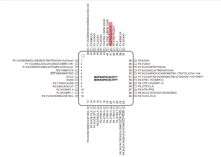
我应该使用哪个针脚来读取频率?
此致,
埃勒姆
你好
我 有一个传感器连接 到 MSP430FR2355启动板。 我有数字输入来计算频率(当分频器通电时)。 我想 测量 来自数字输入的频率分配器(5–6 MHz)的频率。 请 给我一些建议来执行此任务,并为我的编程提供示例代码?
我应该使用哪个针脚来读取频率?
此致,
埃勒姆