请注意,本文内容源自机器翻译,可能存在语法或其它翻译错误,仅供参考。如需获取准确内容,请参阅链接中的英语原文或自行翻译。
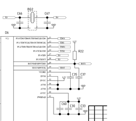
部件号:MSP430FR5729 我尝试将时钟方案配置为:“Crystal 振荡器20MHz -> XTAL1 -> SMCLK”。 分隔器 I 设置为4。
下面是我配置时钟和晶体连接方案的代码。 我预计 SMCLK 输出引脚(PJ.0)的频率为5 MHz,但结果是1.22 MHz。 我不明白为什么,非常希望得到建议,为什么会这么做。
#include <msp430.h>


#ifndef __DATATYPES_H__
#define __DATATYPES_H__


typedef char int8_t;
typedef unsigned char uint8_t;
typedef int int16_t;
typedef unsigned int uint16_t;
typedef long int32_t;
typedef unsigned long uint32_t;
typedef uint8_t BYTE;
#endif

/**
 * main.c
 */

inline void __ClkConf(void);


int main(void)
{
	WDTCTL = WDTPW | WDTHOLD;	// stop watchdog timer

	__ClkConf();

    while(1)
    {
    }

	return 0;
}


inline void __ClkConf(void)
{
    uint16_t temp;

    PJSEL0 |=  BIT0;
    PJSEL1 &= ~((uint16_t)BIT0);
    PJDIR |= BIT0 + BIT4 + BIT5;
    PJOUT |= BIT0 + BIT4 + BIT5;
    PJSEL0 |=  BIT4 + BIT5;          // connect pins to xtal;

    CSCTL0_H = 0xA5;
    CSCTL1 |= DCOFSEL0 + DCOFSEL1;            // Set max. DCO setting
    CSCTL2 = SELA_3 + SELS_0 + SELM_3;        // set ACLK = MCLK = DCO; SMCLK = XTAL1
    CSCTL3 = DIVA_0 + DIVS_2 + DIVM_0;        // set all dividers
    temp = CSCTL4;
    temp |= XTS;
    temp &= ~(XT1OFF);
    CSCTL4 = temp;

}

