

请注意,本文内容源自机器翻译,可能存在语法或其它翻译错误,仅供参考。如需获取准确内容,请参阅链接中的英语原文或自行翻译。
器件型号:MSP430FR2433 主题中讨论的其他器件:ENERGYTRACE
你好,福米特人。
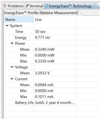
我计划使用2节 AA 电池开发一个为期一年的实验原型。 我的目标是尽可能减小平均电流。 为此、我使用的是 Energy Trace (不是++)、因此我只能看到我的 LaunchPad 消耗了多少电流、或者消耗了多少功率和能量。 显然、出于开发目的、我每8秒记录一次温度。
我使用具有周期性唤醒功能的 LPM3模式、并在唤醒后激活内部温度传感器中断、以便可以执行单次读取并再次进入睡眠模式。 但是、我如何才能从该原型中获得更多能量? 我正在按照 ULP 的建议执行此操作:将 除 A12 (引脚1.2)以外的所有引脚转换为启用下拉的输入。 我将 ACLK 时钟用于 ADC 内核和计时器。 任何建议都值得赞赏。 我不要求任何人给我提供代码、不要让我出错、而是让我激活禁用代码等
我还在睡眠模式下花费100uA (LMP0规定为40uA、根据数据表、LPM3和 RTC 的花费1uA)、必须有一些外设处于活动状态、我需要在某个位置禁用更多外设。
//******************************************************************************
// In this example project, we are mostly sleeping and waking up every 8 seconds
// to measure temperature and record it to FRAM Information Memory Region.
//
// Memory Layout:
//   Byte 1: Session ID(To track how many times recording session is started)
//   Byte 2: How many recordings are saved in the session
//   Byte 3-..: Start to put recordings from byte 3 and onward. Use the counter
//     value in Byte 2 to understand how many readings are valid.
//******************************************************************************

#include <msp430.h>

void FRAMWriteTemp(void);
void FRAMWriteSession(void);
void initGPIOUnusedInputPulldown(void);
void initADC(void);
void initACLKTimer(void);

// See device datasheet for TLV table memory mapping
#define CALADC_15V_30C  *((unsigned int *)0x1A1A)                 // Temperature Sensor Calibration-30 C
#define CALADC_15V_85C  *((unsigned int *)0x1A1C)                 // Temperature Sensor Calibration-85 C
#define FRAM_TEST_START 0x1800

volatile long temp = 0;
volatile long ADC_Value = 0;
unsigned int count = 0;

char *FRAM_start_ptr = (char*) FRAM_TEST_START;
char *FRAM_count_ptr = (char*) (FRAM_TEST_START + 1);
char *FRAM_write_ptr = (char*) (FRAM_TEST_START + 2);

int main(void)
{
    WDTCTL = WDTPW | WDTHOLD;   // stop watchdog timer

    initGPIOUnusedInputPulldown();

    initACLKTimer();

    initADC();

    FRAMWriteSession();

    while (count < 250)
    {
        // The temperature (Temp, C)=
        temp = (ADC_Value - CALADC_15V_30C) * 55
                / (CALADC_15V_85C - CALADC_15V_30C) + 30;
        FRAMWriteTemp();

        __bis_SR_register(GIE | LPM3_bits); // Enable maskables and start Low Power Mode 0
    }

    return 0;
}

// Timer A0 interrupt service routine: Enable the ADC interrupts and start
// ADC conversion. Delay for some time to settle ref voltage setting.
#pragma vector = TIMER0_A1_VECTOR
__interrupt void Timer_A(void)
{
    TA0CTL &= ~(TAIFG);         // Clear the interrupt
    ADCIE |= ADCIE0;            // Enable the conversion complete interrupt;
    ADCCTL0 |= ADCENC | ADCSC;  // Enable and start the conversion
    __delay_cycles(400);        // Delay for reference settling
}

// Record ADC Reading and disable ADC Interrupts. After this ISR, control goes
// to main loop
#pragma vector = ADC_VECTOR
__interrupt void ADC_ISR(void)
{
    __bic_SR_register_on_exit(LPM3_bits);
    ADC_Value = ADCMEM0;

    ADCIE &= ~ADCIE0;            // Disable the conversion complete interrupt;
}

void FRAMWriteTemp(void)
{
    SYSCFG0 = FRWPPW | PFWP; // This instruction removes DFWP, makes FRAM writeable
    *FRAM_count_ptr = (*FRAM_count_ptr) + 1;    // Update count field in FRAM
    *FRAM_write_ptr++ = temp;                   // Record the temperature
    SYSCFG0 = FRWPPW | PFWP | DFWP;     // This instruction locks FRAM again
    count++;                            // Update count
}

void FRAMWriteSession(void)
{
    SYSCFG0 = FRWPPW | PFWP;
    *FRAM_start_ptr = (*FRAM_start_ptr) + 1;
    *FRAM_count_ptr = 0;
    SYSCFG0 = FRWPPW | PFWP | DFWP;
}

void initGPIOUnusedInputPulldown(void)
{
    // Set all P1 pins except 1.2 to input with pulldown resistor
    P1SEL1 = P1SEL0 = 0;
    P1DIR = 0;
    P1OUT &= ~(BIT0 | BIT1 | BIT3 | BIT4 | BIT5 | BIT6 | BIT7);
    P1REN |= BIT0 | BIT1 | BIT3 | BIT4 | BIT5 | BIT6 | BIT7;

    // Set all P2 pins to input with pulldown resistor
    P2SEL1 = P2SEL0 = 0;
    P2DIR = 0;
    P2OUT = 0;
    P2REN = 0xFF;

    // Set all P3 pins to input with pulldown resistor
    P3SEL1 = P3SEL0 = 0;
    P3DIR = 0;
    P3OUT = 0;
    P3REN = 0xFF;

    // Finally, set P1.2 to analog function
    P1SEL1 |= BIT2;
    P1SEL0 |= BIT2;             // Set 11 to both bits for Temp Sensor(A12 -> P1.2)

    PM5CTL0 &= ~LOCKLPM5;       // Turn on IO
}

// Configure Analog 12(Internal Temp Sensor)
void initADC(void)
{
    // Configure the ADC
    ADCCTL0 &= ~ADCSHT_15;      // Clear Conversion Clock Cycles
    ADCCTL0 |= ADCSHT_1;        // Set SHT to 8 Conversion Clock Cycles
    ADCCTL0 |= ADCON;           // Set ADC Core on

    ADCCTL1 |= ADCSSEL_1;       // Choose ACLK as Source Clock
    ADCCTL1 |= ADCSHP;          // Sample signal source = sampling timer
    //ADCCTL1 |= ADCDIV_7;      // ADC Clock Divider set to /8 to slow sampling

    ADCCTL2 |= ADCRES_1;        // 10-bit conversion results
    //ADCCTL2 |= ADCPDIV__64;   // ADC Pre Clock Divider set to /64 to slow sampling

    ADCMCTL0 |= ADCSREF_1 | ADCINCH_12;      // Set A2 as ADC Input

    // Configure reference
    PMMCTL0_H = PMMPW_H;                             // Unlock the PMM registers
    PMMCTL2 |= INTREFEN | TSENSOREN; // Enable internal reference and temperature sensor
}
// Intended to raise interrupt every 8 seconds to initiate temperature sensing
void initACLKTimer(void)
{
    TA0CTL |= TASSEL__ACLK;                     // Set clock source to ACLK
    TA0CTL |= TAIE;                             // Enable Timer A Interrupts
    TA0CTL |= TACLR;                            // Clear Timer A Register
    TA0CTL |= ID_2;                             // Slow Timer by 2^X (ID_X)
    //TA0EX0 |= TAIDEX_7;                       // Slow timer by Y+1 times (TAIDEX_Y)
    TA0CTL |= MC__CONTINUOUS;                   // Set continuous mode
}
