


请注意,本文内容源自机器翻译,可能存在语法或其它翻译错误,仅供参考。如需获取准确内容,请参阅链接中的英语原文或自行翻译。
器件型号:MSP-EXP430G2
尝试使 I2C 传输在 MSP-EXP430G2上正常工作。 需要将 SMCLK 以~100kHz 的频率连接到 SCL。 我将一个逻辑分析仪连接到 SDA 和 SCL、并连接了4.7K 外部上拉电阻。 启动时、这两个信号都保持高电平。 我当前未连接 I2C 从器件、因此我希望发送的从器件地址不包含 ACK。
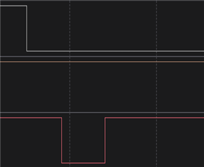
如果逻辑分析仪仅连接到 SCL 和 SDA、我将看到以下行为。 红色= SCL、白色= SDA:
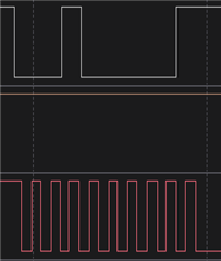
我在 while 循环开始处的断点处停止代码。 我将逻辑分析仪连接到 P1.4上设置的 SMCLK 输出引脚、并保留 SDA 和 SCL 的连接。我看到下面的输出。 红色= SCL、白色= SDA:
我是否在时钟或 I2C 配置中遗漏了某个东西?
我的完整代码如下所示:
#include <msp430G2113.h>

unsigned char TXData;
unsigned char TXByteCtr;

int main(void)
{
  WDTCTL = WDTPW+WDTHOLD;

  BCSCTL1 = CALBC1_1MHZ;
  DCOCTL = CALDCO_1MHZ;
  BCSCTL2 |= SELM_1 | DIVM_0 | DIVS_0;

  P1DIR |= BIT4;
  P1REN = 0;
  P1SEL |= 0xC0;
  P1SEL2 |= 0xC0;
  P1SEL |= BIT4;
  P1SEL2 &= ~BIT4;
  UCB0CTL1 |= UCSWRST;                      // Enable SW reset
  UCB0CTL0 = UCMST + UCMODE_3 + UCSYNC;     // I2C Master, synchronous mode
  UCB0CTL1 |= UCSSEL_2;                     // Use SMCLK, keep SW reset
  UCB0BR0 = 10;                             // fSCL = SMCLK/10 = ~100kHz
  UCB0BR1 = 0;
  UCB0CTL1 &= ~UCSWRST;                     // Clear SW reset, resume operation
  IE2 |= UCB0TXIE;                          // Enable TX interrupt

  TXData = 0x01;                            // Holds TX data

  UCB0I2CSA = 0x10;                         // Slave Address is 0x10
  while (1)
  {
    TXByteCtr = 1;                          // Load TX byte counter
    while (UCB0CTL1 & UCTXSTP);             // Ensure stop condition got sent
    UCB0CTL1 |= UCTR + UCTXSTT;             // I2C TX, start condition
    __bis_SR_register(CPUOFF + GIE);      // Enter LPM0 w/ interrupts
                                            // Remain in LPM0 until all data
                                            // is TX'd
    TXData++;                               // Increment data byte
  }
}


//------------------------------------------------------------------------------
// The USCIAB0TX_ISR is structured such that it can be used to transmit any
// number of bytes by pre-loading TXByteCtr with the byte count.
//------------------------------------------------------------------------------
#if defined(__TI_COMPILER_VERSION__) || defined(__IAR_SYSTEMS_ICC__)
#pragma vector = USCIAB0TX_VECTOR
__interrupt void USCIAB0TX_ISR(void)
#elif defined(__GNUC__)
void __attribute__ ((interrupt(USCIAB0TX_VECTOR))) USCIAB0TX_ISR (void)
#else
#error Compiler not supported!
#endif
{
  if (TXByteCtr)                            // Check TX byte counter
  {
    UCB0TXBUF = TXData;                     // Load TX buffer
    TXByteCtr--;                            // Decrement TX byte counter
  }
  else
  {
    UCB0CTL1 |= UCTXSTP;                    // I2C stop condition
    IFG2 &= ~UCB0TXIFG;                     // Clear USCI_B0 TX int flag
    __bic_SR_register_on_exit(CPUOFF);      // Exit LPM0
  }
}
